On the mechanism and control for the ultra-low frequency oscillation in NY Power Grid with large-scale hydropower
2019-07-26AnchengXUEJiaweiWANGChaoZHENGJoeCHOWTianshuBI
Ancheng XUE ,Jiawei WANG ,Chao ZHENG ,Joe H.CHOW ,Tianshu BI
1.State Key Laboratory of Alternate Electrical Power System with Renewable Energy Source(North China Electric Power University),Changping District,Beijing 102206,China;2.China Electric Power Research Institute,Haidian District,Beijing 100192,China;3.Department of Electrical,Computer and Systems Engineering,Rensselaer Polytechnic Institute,Troy 12180,New York State,U.S.A.
Received 4 December 2018;revised 26 January 2019;accepted 25 February 2019
Abstract The power grid with large proportion of hydropower may engage the ultra-low frequency oscillation(ULFO),which threatening the operation of system.To the NY Power Grid system,whose dimension is over thousands,this paper reveals the cause of ULFO with the phase portrait method,i.e.,lies in the saturation of the different limits of the governor system of the generators,in other words,the occurrence of limit cycle is due to the non-smooth bifurcation.And furthermore,it proposes two methods to suppress ULFO with the philosophy of destroying the condition of non-smooth bifurcation.In detail,first,the phenomenon of ULFO in NY Power Grid,the damping characteristics and the limits in the governor system of the hydropower units are presented.Second,based on the non-smooth bifurcation theory,the mathematical basis of the oscillation in the non-smooth system caused by the saturation of limits is introduced.And then,the non-oscillation and oscillation dynamic of the system corresponding to without/with limits in the governor system are analyzed.Furthermore,it discusses the influence of the saturation of single limit on the characteristics of ULFO with the phase portraits.Moreover,the phase portraits of the ULFO under different faults is analyzed,and it shows that the limiting saturation occurs with a large enough disturbance.Thus,the ULFO is resulting from the negative damping of generation and the saturation of multiple limits under a large enough disturbance.In addition,according to the above mechanism,two strategies to suppress the ULFO,i.e.,the governor parameters tuning and the fault strength relief are designed.The simulation shows the effectiveness of proposed strategies.
Keywords:Ultra-low frequency oscillation,governor system,limit,non-smooth bifurcation,limit cycle
1 Introduction
Low-frequency oscillation is one of the important factors that constraints the power transmission capacity and threatens the security of the electric power grid,whose oscillation frequency is generally between 0.1-2.5 Hz[1,2].However,recently,many ultra-low frequency oscillations(ULFOs)have occurred in the actual system.The ULFOs,with lower oscillation frequency and longer oscillation period,may be extreme dangerous.Thus,they have attracted a lot of attentions.
As ULFO is a special low frequency oscillation,therefore,the mechanism,the analytical method and the suppression control method of low frequency oscillation can also be applied to the ULFO[1-4].Thus,there have been many works related to the mechanism,the analytical methods and control for the ULFO[5-14].
In[5],with the analysis for the oscillation mode,it reveals that the ULFO is a mechanical oscillation caused by the governor system.J.He et al.[6]analyzed the ULFO with frequency 0.071 Hz and amplitude±0.26 Hz in JS HVDC line,and the result shows that the main cause of the ULFO is the instability of governor system.C.Liu et al.[7]concluded the governor system of hydropower units with negative damping is the direct cause of the ULFO of Yunnan Power Grid,with a large number of field data analysis.While Y.Chen et al.[8,9]showed that the ULFO is a type of forced-like oscillation,which exhibits a negatively damped oscillation in the start-up stage and oscillates in a resonant form during the continuous oscillation stage.
To damp the ULFO,Y.Chen[8]switched the automatic control to the manual control of the generators located as the sources of oscillation.J.Zhang et al.[10]analyzed the influence of governor system parameters on the damping ratio of the ULFO,and proposes the oscillation suppression measures based on parameters tuning.F.Wang et al.[11]used the frequency limiting controller(FLC)to control the ULFO in Southwest Power Grid,with the DC modulation.W.Li et al.[12]suppressed the ULFO of an islanding power system with two methods,one is withdrawing the primary frequency modulation function of some generators,and the other is coordinating the dead zone of the primary frequency modulation of the hydropower units and FLC.C.Gencoglu et al.[13,14]introduced the control method for ULFOs in Turkey and Colombia by optimizing the governor parameters and increasing the thermal plants’capacity,respectively.
It is worth to note that the current control methods for the ULFOs are mainly based on the cognition of“the negative damping result in oscillation”.However,the simulation results show that,the ULFOs occurred in the NY Power Grid may be explained by the negative damping of the hydropower units,but it only occurs under some specific fault conditions.In essence,the ULFO in NY Power Grids may be different from the previous ULFOs[8,9].Thus,the mechanism of ULFOs is not complete,and the control method also needs further analysis.
On the other hand,it is worth to note that,in addition to the negative damping,the saturation of limits can also result in oscillations.For example,V.Venkatasubramanian et al.[4,15-18]discussed the oscillation of single-machine-infinite-bus power system result from the limits in excitation system.Y.Dai et al.[19]showed that,under large disturbance,the saturation of limits in reheating steam turbine will result in a stable limit cycle and the unattenuated oscillation.In[20],the nonsmooth bifurcation theory is applied to analyze the low frequency oscillation caused by the saturation of limits.In addition,Y.Zhao et al.[21]stated that the ULFO is result from the nonlinear characteristics of the power system.
In recognizing the above problems,this paper discusses the mechanism of the ULFOs of NY Power Grid and then proposes two preliminary control measures,with the viewpoint of the oscillation resulted from the saturation of limits.After determining the negative mechanical damping of the hydropower units is one of the causes of ULFO,this paper shows that the ULFOs are also result from the saturation of multiple limits in the governor system,especially with a large enough disturbance which could activate the saturation of limits,with the phase portraits method.
The above work reveals the mechanism of the ULFO with a new viewpoint.It could not only serve as a supplement to the mechanism of ULFOs,but also guide the controller designing to suppress the ULFOs.
The remainders of the paper are organized as follows.Section 2 introduces the ULFOs occurring in the NY Electric Power Grid,with the analysis for the mechanical damping of the hydropower units,and then presents the internal variables dynamic of governor system with the saturation of limits.Section 3 briefly presents the theory of non-smooth bifurcation and the limit-saturation induced oscillation.Section 4 compares the non-oscillation and oscillation phenomena in the NY Power Grid system,which is corresponding to without and with limits in the governor system,and verifies that the oscillation is strongly related to the limits.Section 5 discusses the influence of removing different limits on the characteristics of oscillation with the phase portraits,and verifies that the oscillation is result from the saturation of multiple limits.Section 6 analyzes the phase portraits of the ULFO under different faults,and shows that the saturation of limits occurs with a large enough disturbance,i.e.,the large enough disturbance is also one of the cause for the ULFO.Section 7 proposes two strategies to suppress the ULFO,i.e.,the governor parameters tuning and the fault strength relief.Finally,Section 8 presents the conclusions and discussions.
2 The ULFO and saturation of limits
2.1 The ULFOs in NY Electric Power Grid
The NY Electric Power Grid contains more than 800 generators,and 70%of them are the hydropower units.Then,the dimension of the state space of the electric power system are over 4,000,thus,it is impossible to analyze the system theoretically,so the main results of this paper are based on the simulations.
The simulation results show that,under the GH-QB double-circuit N-2 fault,the ULFO will occur in NY Electric Power Grid,as shown in Fig.1.And the frequency and the amplitude of oscillation are 0.065 Hz,and±0.2 Hz,respectively.
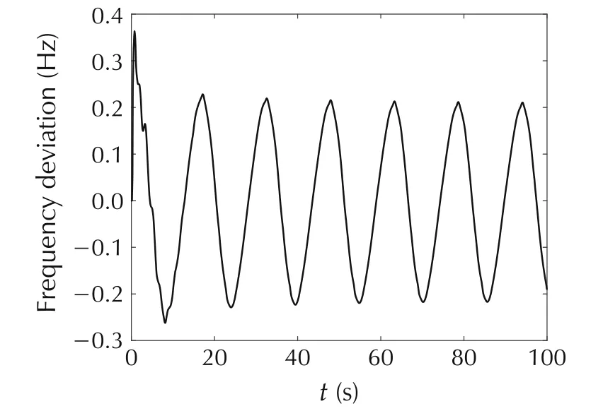
Fig.1 System frequency response under GH-QB N-2 fault.
2.2 Damping characteristic of the hydropower units
The power system oscillation is related to the negative damping.With the fact that 70%of the units in NY Electric Power Grid are hydropower,so special consideration is given to the governor systems of the hydropower units,which determine the frequency responses.
According to[7],taking the DJ#2 hydropower unit as an example,the damping coefficient with the different TW(water hammer constant varying with different operating conditions,it could be 1,2 and 3)can be obtained as shown in Fig.2.
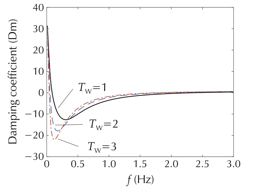
Fig.2 Damping characteristic curve of hydropower unit.
Fig.2 shows that the hydropower unit provides negative damping in the ultra-low frequency range.Furthermore,the larger of the TW,the stronger of the negative damping.Thus,the system is more prone to occurring ULFO.
According to the damping characteristic analysis,the hydropower units with large capacity over 100 MW in this NY Electric Power Grid are engaging with the negative mechanical damping under the ULFO frequency 0.065 Hz,especially the large generators with capacity of 600 MW and 770 MW.Therefore,the system has a negative damping characteristic at the ULFO with 0.065 Hz,as a whole.And the insufficient mechanical damping of the governor system of the hydropower units is one of the reasons for the ULFO.
2.3 Saturation of limits in governor system
The governor system of hydropower units includes three parts,i.e.,the regulating system,the electrohydraulic servo system and the hydraulic turbine.In the simulation,the GM model for the regulating system,GA model for the electro-hydraulic servo system and TW model for the hydraulic turbine are used,as shown in Fig.3.
Fig.3 shows that the models for the governor system of hydropower unit have various limits.The GM model has the primary frequency modulation limit(represented with state FREQ),the output limit in the PID.The GA model has the over-speed closing/opening limit(represented with state PTCO)and the guide vane opening limit(represented with state PGV1).
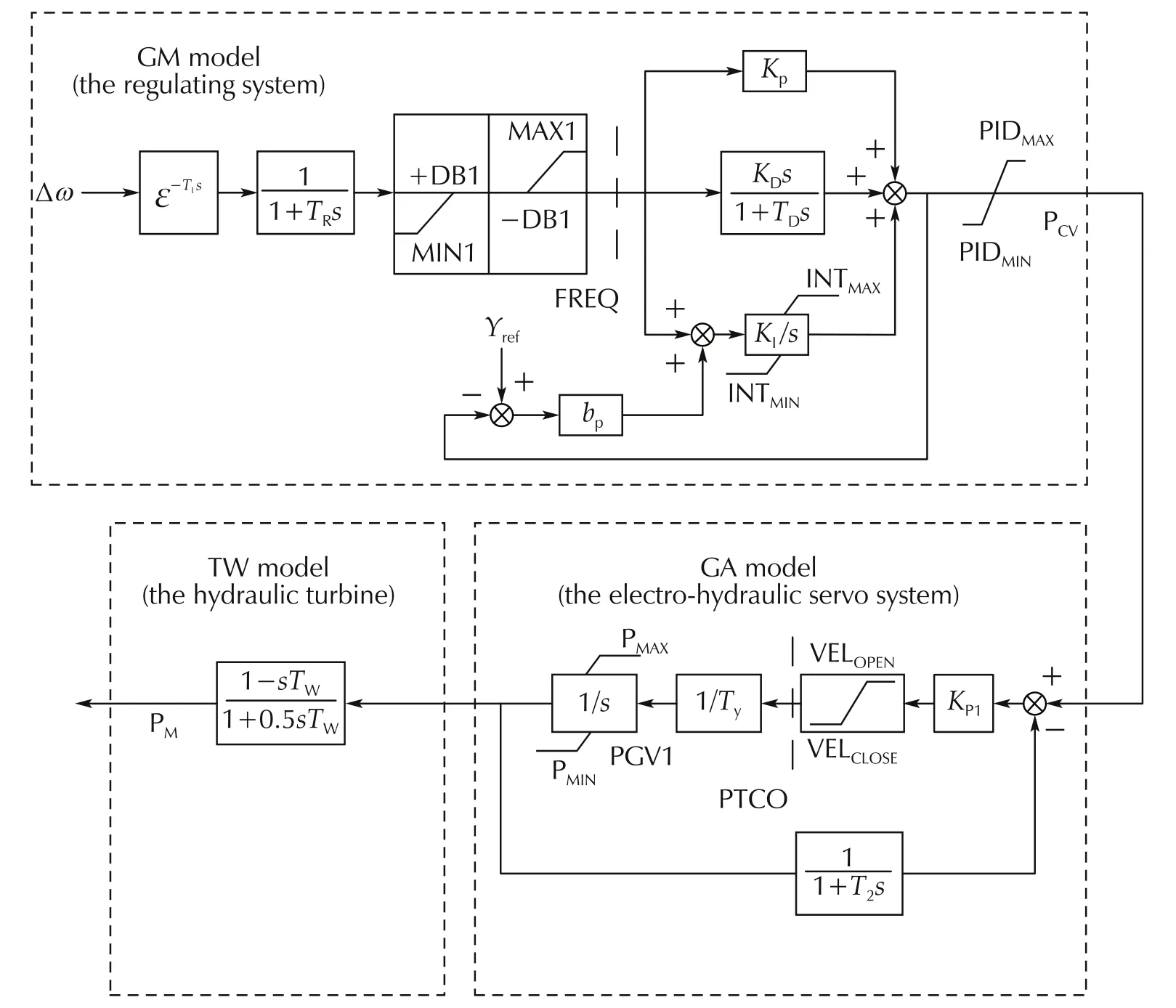
Fig.3 The model of governor system.
For the ULFO in Fig.1,the value of internal variables PTCO and PGV1 of governor system of DJ#2 can be obtained.Thus,the phase portraits of PTCO-PGV1 of DJ#2 can be plotted,as shown in Fig.4.
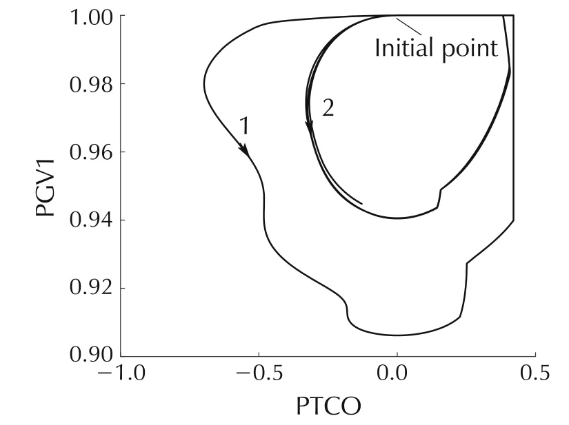
Fig.4 PTCO-PGV1 phase portrait of DJ#2.
Fig.4 shows that,in the ULFO,the internal variable response will be restricted by the limits,or the limits are saturated.
As stated in the introduction,for a nonlinear system,the system oscillation may relate to the saturation of the limits[15-21].Therefore,the presented ULFO may also engage this characteristic,it would be analyzed below.
3 Non-smooth bifurcation and limit-induced oscillation
This section introduces the theory of oscillation resulting from the limiting saturation with the viewpoint of non-smooth bifurcation,i.e.,the existence of the switching(limiting saturation)interface leads to the stable limit cycle for the non-smooth system.
Mathematically,the differential power system with limits is a non-smooth system.For the non-smooth systems with the switching interface,its dynamic characteristics may be very complex.For example,a singlemachine-infinite-bus power system with the excitation limit will engage a stable oscillation resulted from the saturation of limit,i.e.,hard-limit induced oscillation[15-21].
From the perspective of bifurcation,the above oscillation is also related to the non-smooth system bifurcations.The non-smooth bifurcations mainly include the Corner-collision bifurcation(C-bifurcation)and the grazing bifurcation,as shown in Fig.5.
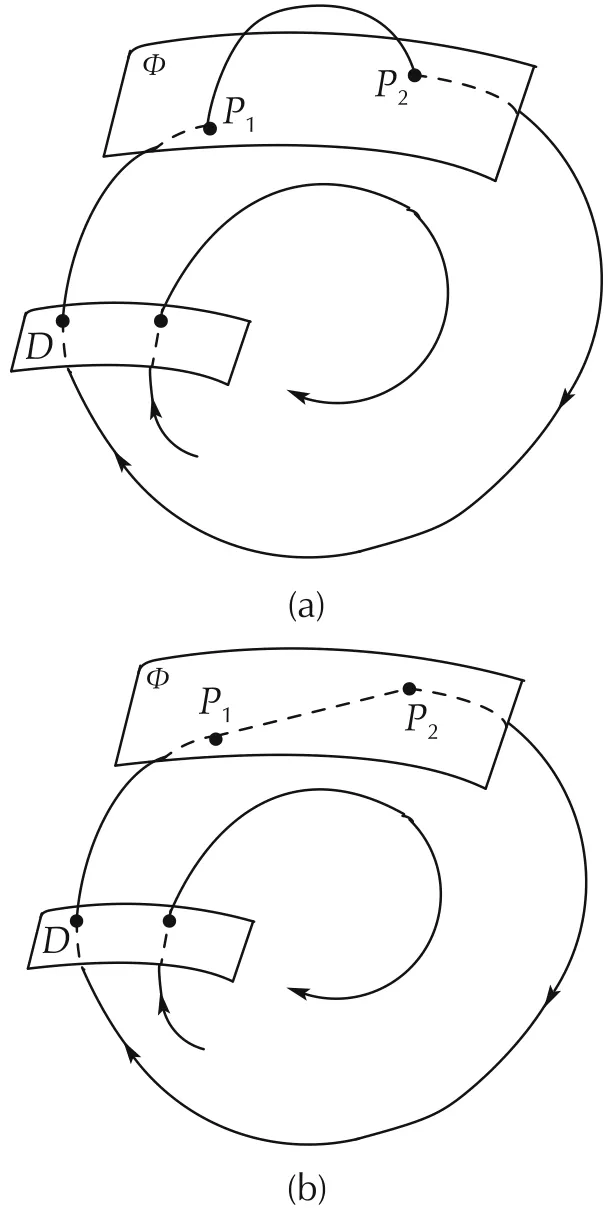
Fig.5 Non-smooth bifurcation diagram.(a)C-bifurcation.(b)Grazing bifurcation.
In Fig.5,D is a generic Poincare plane transversal to the system flow.For the Poincare mapping,if there is a fixed point with all the modus of the eigenvalues are less than 1,the system will have a stable limit cycle.That is,under appropriate parameters and initial conditions,the system exhibits stable oscillation,i.e.,a stable limit cycle.Furthermore,for the case with multiple limits(non-smooth tangent planes),it is possible that the limit cycle(or oscillation)associated with different switched surface exists,as shown in Fig.6.
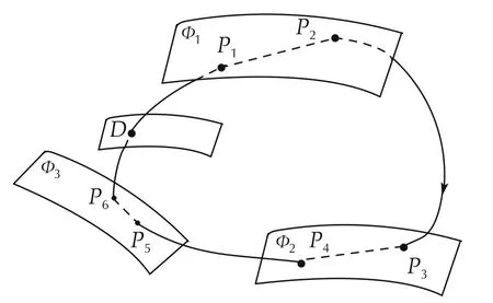
Fig.6 Schematic diagram of oscillation caused by multiple limits.
From Section 2.3,it can be seen that there are multiple limits in the governor system and the limits are saturated when oscillation occurs.This situation is similar to the principle shown in Fig.6.In the following,the mechanism of ULFO will be analyzed with the combination of phase portraits and governing system limits.
4 Variation of oscillation with/without limits
This section compares the variation of the oscillation characteristics and the phase portraits of the NY Electric Power Grid,under the condition of without and with limits in the governor system,and verifies that the ULFO is related to the limiting saturation,i.e.,the ULFO is corresponding to the non-smooth system bifurcation.
By removing the limits in the governor system of all hydropower and thermal power units in NY Power Grid ideally,the dynamic of the variables is not constrained by the limits.And the corresponding system frequency response and guide vane opening of DJ#2,(i.e.,the internal variable PGV1)can be obtained as shown in Fig.7 and Fig.8.
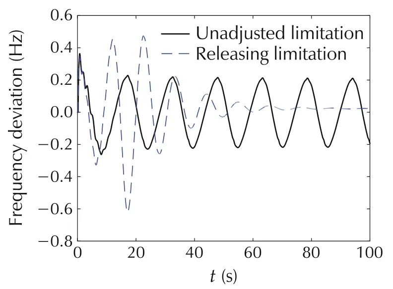
Fig.7 System frequency response curve.
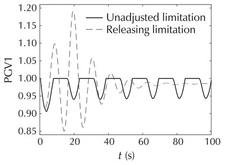
Fig.8 Response curve of guide vane opening PGV1.
Fig.7 shows that if all the limits of governor system are removed,the system frequency will experience an oscillation with larger amplitude and then become stable after the N-2 fault,i.e.,the system is stable without limits.It is important to note that this limit-remove may not match the actual situation.As shown in Fig.8,the maximum value of guide vane opening will exceed the actual limit.However,theoretically,the existence of limits is one of the reasons for the oscillation.
Furthermore,the phase portraits of PTCO-PGV1 of DJ#2 in the case of without/with limits can be plotted,as shown in Figs.9 and 10,respectively.
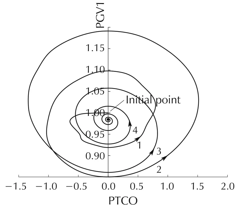
Fig.9 PTCO-PGV1 phase portrait of DJ#2 after releasing all limits.
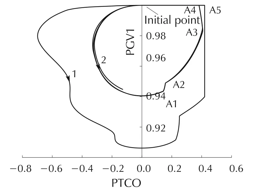
Fig.10 PTCO-PGV1 phase portrait of DJ#2 with unadjusted limitation.
Fig.9 shows that the PTCO-PGV1 trajectory is a smooth curve and the system is finally stable.Fig.10 shows that when the limits exist,the internal variables PTCO and PGV1 are constrained(saturation of limit)and result in a stable oscillation.Furthermore,there are five non-smooth points A1-A5,i.e.,continuous but not derivative points,in the phase portrait induced by the saturation of limits.Therefore,it is very likely that the sequence of the saturation of the limits causes the system oscillation,or the ULFO is related to multiple limits.This will be further verified in Section 5.
Meanwhile,Fig.10 shows that the limits of PTCO and PGV1 are both saturated.In particular,from the viewpoint of PGV1,the effect of limiting-saturation is similar to the Grazing bifurcation.
5 Influence of remove one limit
This section analyzes the effects of the primary frequency modulation limit(for variable FREQ),the overspeed closing/opening limit(for variable PTCO)and the guide vane opening limit(for variable PGV1)on the characteristics of ULFO,and shows that the remove of different limits will have different effects on the oscillation characteristics.
Specifically,this section analyzes the effects of removing single limit in all units on the characteristics of the ULFO.Specifically,the following scenarios are considered:
Case 0:any limits unchanged in units;
Case 1:without the primary frequency modulation limit;
Case 2:without the over-speed closing/opening limit;
Case 3:without the guide vane opening limit.
For the above four cases,the system frequency responses under N-2 fault are shown in Fig.11.Correspondingly,the amplitude and frequency of the ULFOs are shown in Table 1.
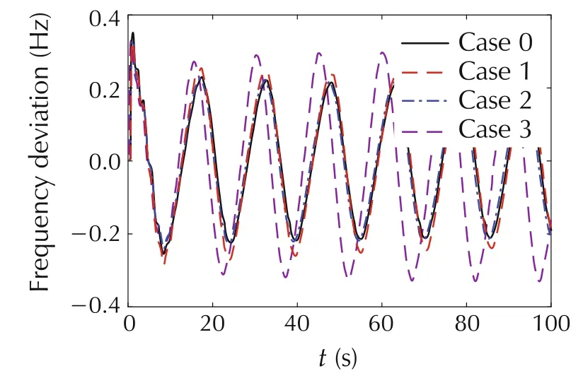
Fig.11 System frequency response after releasing a single limit.
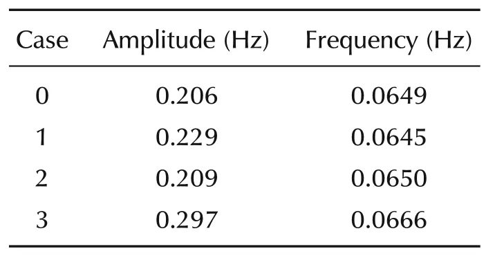
Table 1 ULFO characteristics after releasing a single limit.
Fig.11 and Table 1 show that,from the perspective of different limits,removing the guide vane opening limit PGV1(Case 3)can increase the maximum output power of prime mover,which increases the maximum capacity of the system to withstand the disturbance,so it has the greatest influence on the ULFO.Removing the primary frequency modulation limit FREQ(Case 1)has the second-order effect on the ULFO,and removing the over-speed closing/opening limit PTCO(Case 2)has the least influence.Generally,the three types of limits all have effect on the ULFO,compared to Case 0.In additional,the above results show that the remove of any type single limit does not change the system to be stable.With the fact that the system is stable if remove all limits,it can be concluded that the saturation of limits can enhance the form of ULFO.
Furthermore,the phase portraits of the Δ f-PTCO and PTCO-PGV1 for the different cases are plotted in Fig.12 and Fig.13,respectively.In each case,four non-smooth points are marked,i.e.,B1-B4.
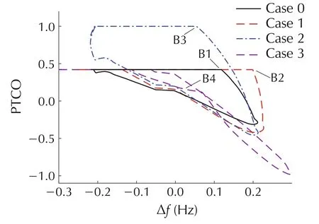
Fig.12 Δf-PTCO phase portrait of DJ#2 after releasing a single limit.
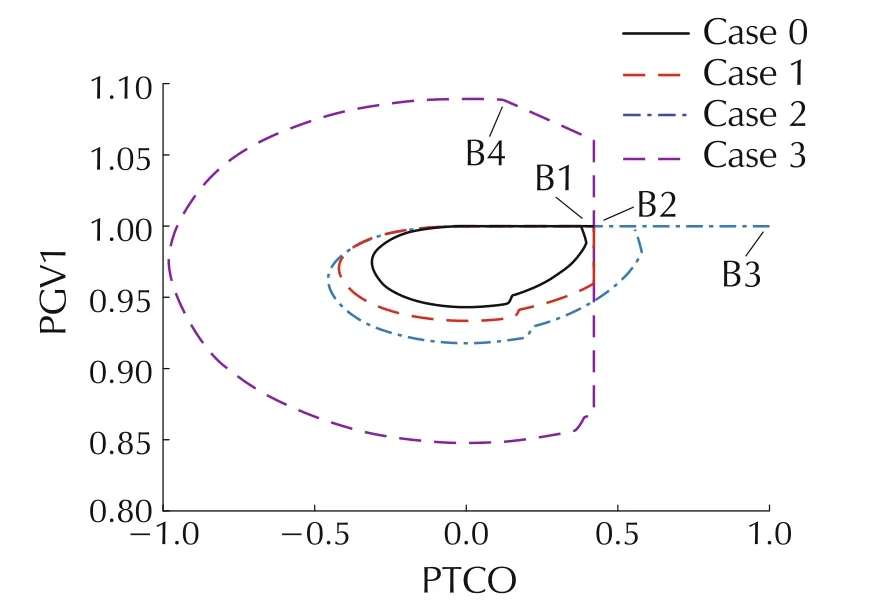
Fig.13 PTCO-PGV1 phase portrait of DJ#2 after releasing a single limit.
As shown in Figs.12 and 13,the ULFOs still exist after removing any one limit.In Case 1,when removing the FREQ limit,the corresponding phase portrait changes,and the PTCO limit is saturated and the bifurcated point is change from B1 to B2.In Case 2,the PTCO limit is not saturated,but the corresponding phase portrait has a new non-smooth point at B3,indicating that the integral limit or the output limit of PID before the PTCO limit is saturated.Similarly,in Case 3 which removing the PGV1 limit,a new non-smooth point B4 induced by some other limits appears.Furthermore,compared to Case 0,the changes in trajectory indicate that the PGV1,FREQ,and PTCO limits are all saturated.Thus,different limits will affect the ULFO and jointly determine the internal variables dynamic of governor system.Therefore,the ULFO is not the result of saturation of a single limit,but multiple limits.
6 Influence of different faults
This section analyzes the difference of the phase portraits of the ULFOs under different fault duration,and verifies that the saturation of multiple limits under a large enough fault disturbance is one of the cause for the ULFOs.
For the GH-QB double-circuit N-2 fault,considering different fault duration,i.e.,40 ms,80 ms and 120 ms,then,the frequency responses of the system can be obtained,as shown in Fig.14,and the corresponding phase portraits of the PTCO-PGV1 and PGV1-Δ f under different fault durations are shown in Figs.15 and 16.
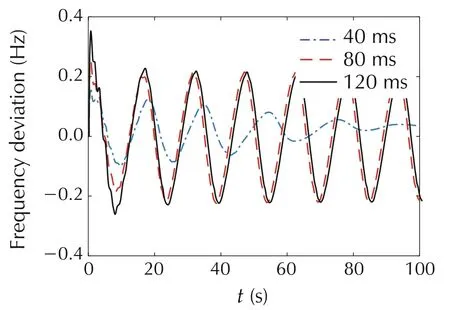
Fig.14 System frequency response under different fault durations.
Fig.14 shows that the ULFO is disappeared when the fault duration is 40 ms,and it exists when the fault duration is 80 ms or 120 ms.Figs.15 and 16 show that when the fault duration is 40 ms,the trajectory in the phase portrait is stable and the limits of PGV1 and PTCO are not saturated.When the fault duration is 80 ms or 120 ms,there are five non-smooth points in the system,indicating that the system variables are always constrained by at least five times,and the system eventually forms ULFO.
Therefore,different disturbances result in the saturation of different sets of limits,which will cause different characteristics.While the different fault durations mean different degrees of fault(i.e.,the longer duration time,the more serious of the fault).Thus,the three cases in Fig.14 show that,the serious faults which make the saturation of multiple limits in governor system,could eventually result in ULFO.
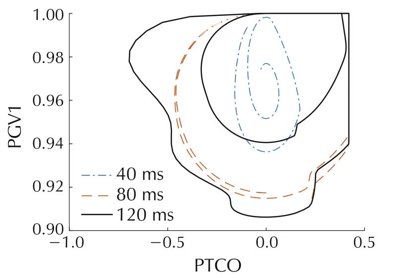
Fig.15 PTCO-PGV1 phase portrait of DJ#2 with different fault durations.
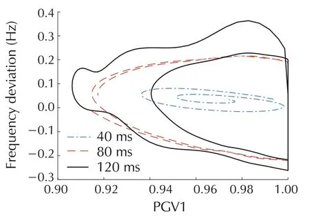
Fig.16 PGV1-Δ f phase portrait of DJ#2 with different fault durations.
It is worth to note that the negative damping characteristic for the system remains unchanged.Therefore,the occurrence of the ULFO,is not only the result of the saturation of different limits which is analyzed previously,but also the large enough disturbance which could make the limits saturated.
Mathematically,in the viewpoint of different-algebraic equation which describing the power system,when the parameters of governor system are fixed and the steadystate power system are same after the fault,then the parameters and the stable equilibrium point of the system after the fault are same.While the different duration time of fault will lead to different initial values of the system after the fault is removed.The different initial values will determine the saturation/non-saturation of the different limits.When different limits are saturated,the system and limits interaction may cause the occurrence of limit cycle,which is physically manifested as ULFO.On the other hand,it is also possible that the system does not oscillate although some limits are saturated.
7 Preliminary controllers for the ULFO
According to the mechanism of ULFO analyzed previously,this section proposes two preliminary methods to suppress the ULFO,one is adjusting the governor parameters to reduce the negative damping,the other is reducing the fault strength to prevent the ULFO.
7.1 Controller based on parameters adjustment
Taking the DJ#2 hydropower unit of NY Power Grid as an example,the mechanical damping under different PI parameters can be obtained as shown in Fig.17,where KPand KIrepresent the proportional and integral coefficients of the governor system,respectively.
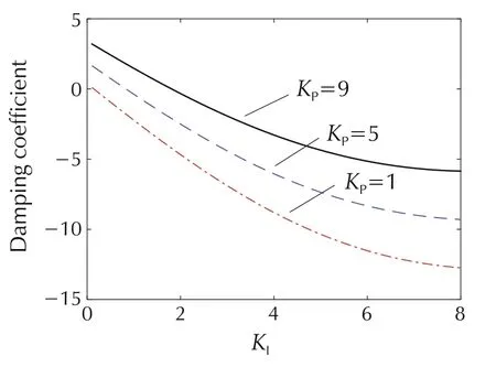
Fig.17 Effect of PI parameters on mechanical damping.
Fig.17 shows that,with the change of PI parameters,the mechanical damping coefficient could be changed from negative to positive.Thus,with suitable adjustment,the ULFO may be controlled.
According to the above analysis,in order to avoid the assessment of the primary frequency modulation performance,furthermore,as the parameter KIdecreases,the mechanical damping coefficient will increase significantly,while the increase of parameter KPwill also cause the increase of damping coefficient.Thus,the decreasing of the KI&KPmay result in reducing negative damping of the hydropower units and suppressing the ULFO of the power grid.
According to the above method,reducing the PI parameters of the hydropower plants of DJ,GBP and DG with the largest capacity and negative damping in the NY Power Grid,from KP=9 and KI=7 to KP=5 and KI=0.2,then,the mechanical damping of each governor system can be obtained,as shown in Table 2.
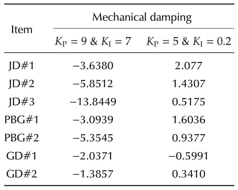
Table 2 Comparison of mechanical damping before and after changing PI parameters.
Table 2 shows that after adjusting,the mechanical damping of high-capacity generators is improved,which is beneficial to the oscillation attenuation.
With the parameters adjustment,the system frequency response under the same fault can be obtained,as shown in Fig.18.
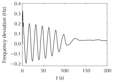
Fig.18 System frequency response after changing governor parameters.
Fig.18 shows that by adjusting the governor PI parameters,the damping of the system is increased,and,therefore the ULFO is suppressed effectively.
7.2 Controller based on reducing fault strength
As one of the cause of the ULFO is a large enough disturbance.Thus,by reducing the fault strength,the ULFO may be suppressed.To reduce the fault strength,the frequency limiting controller(FLC),which could balance the demand and need locally,can be used.
The structure diagram of FLC is shown in Fig.19.
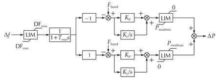
Fig.19 The structure diagram of FLC.
In Fig.19,DFmaxand DFminare the maximum and minimum limits of frequency deviation respectively,Tfis the filter time constant,Fbandis the dead-zone of frequency deviation,KPis the proportional coefficient,KIis the integral coefficient,Pmodminand Pmodmaxare the lower and upper limits of DC power regulation.
The input signal of the FLC is the frequency deviation Δ f of the AC system and the final output signal is the DC power modulation amount ΔP,i.e.,the reference value of DC power is changed according to the frequency of AC system.Therefore,the FLC enables the system to maintain the active power balance and is widely used to maintain the stable operation of AC and DC systems[22].
In this paper,six FLCs are added to the conventional DC sending ends of NY Power Grid.The FLC adopts the general parameters,its setting are as follows:DFmax=5.0,DFmin=-5.0,Fband=0.04 Hz,Tf=0.05,Pmodmax=+30%,Pmodmin=-50%,KP=30,KI=5.With the above FLCs,the system frequency response after the N-2 fault can be obtained,as shown in Fig.20.Furthermore,the active power on the LF-XF DC line is shown in Fig.21.
Figs.20 and 21 show that during the transient response process,the DC line reduces the active power of AC line by increasing its own power amplitude.From the viewpoint of energy,when the disturbance causes the energy imbalance between the receiving end and sending end,the FLC can perform power support in the transient response,and weaken the influence of unbalanced energy.It is equivalent to reducing the fault strength,therefore the ULFO is suppressed.
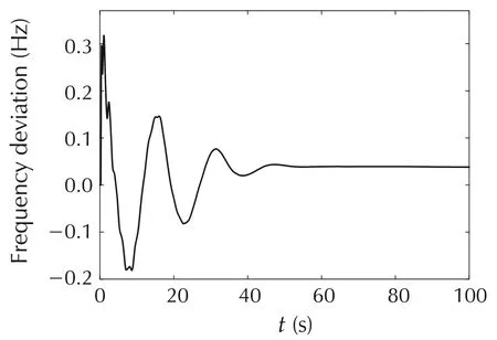
Fig.20 System frequency response after inputting FLC.
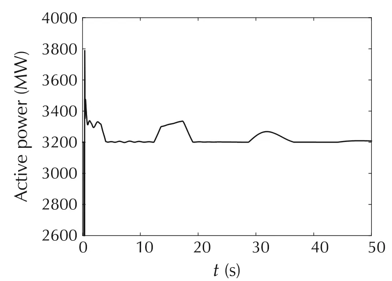
Fig.21 Power on the DC line after inputting FLC.
Therefore,for AC and DC hybrid systems,DC is a rigid load,and the transmission power is not affected by the frequency fluctuations.The input of FLC makes the DC to have the frequency characteristics,and makes the active power of the AC and DC system balanced,which is beneficial to the system frequency stability.
8 Conclusions and disucssions
Ultra-low frequency oscillation(ULFO)in NY Power Grid is a threat to the power system operation.This paper analyzes the mechanism of ULFO and presents different control strategies to suppress it.
The analysis of the influences of the limits of governor systems on the ULFOs,based on simulation,revealed that the cause of ULFO is not only the negative mechanical damping of large hydropower units in the ultra-low frequency band and the forced-like oscillation,but also the saturation of multiple limits of the governor system under large enough disturbance.The analysis with phase portraits shows that the ULFO is corresponding to the occurrence of the limit cycle due to non-smooth bifurcation.The simulation results of two preliminary control strategies,i.e.,the governor parameters adjustment and the fault strength reduction,which aiming at destroying the condition of non-smooth bifurcation,according to the mechanism analysis,verified the effectiveness of the proposed suppression strategies to ULFO.
On the other hand,this work is based on the simulation,thus,there is still a lot of theoretical work to do,especially for the single-machine-infinite-bus system with low dimension.Furthermore,the control strategies proposed in this paper are preliminary,and more works on developing the controller are still needed.
杂志排行
Control Theory and Technology的其它文章
- Parallel loop recovery with quiescent compensation for high performance feedback control of systems with imperfect actuators
- Nonlinear observer-based control design and experimental validation for gasoline engines with EGR
- Invariant observer design of attitude and heading reference system
- Guaranteed feasible control allocation using model predictive control
- Diagnosability of a class of discrete event systems based on observations
- Optimal finite-dimensional spectral densities for the identification of continuous-time MIMO systems
