Invariant observer design of attitude and heading reference system
2019-07-26MartinBARCZYK
Martin BARCZYK
Department of Mechanical Engineering,University of Alberta,Edmonton AB T6G 1H9,Canada
Received 13 February 2018;revised 24 May 2018;accepted 21 December 2018
Abstract An attitude and heading reference system(AHRS)is a nonlinear state estimator unit for computing orientation in 3D space.This paper designs an AHRS using three approaches:an invariant observer,an invariant extended Kalman filter(IEKF),and a conventional extended Kalman filter(EKF).The three designs are validated in experiment versus a ground truth,demonstrating the practical interest of the invariant observer methodology and the advantage of the IEKF over the EKF under model uncertainty.
Keywords:Inertial navigation,state estimation,Kalman filters,nonlinear dynamical systems,covariance matrices
1 Introduction
An attitude and heading reference system(AHRS)is a unit employed in aerospace,land vehicle and robotics applications to indicate the orientation of a body in 3D space.The name AHRS comes from aviation where“attitude”means roll and pitch angles of the vehicle,while“heading”refers to its yaw angle w.r.t.magnetic north[1,Pages 3-22].In modern strapdown AHRS units,this is accomplished by first estimating the attitude and heading from numerical integration of the(nonlinear)rotational kinematics using high-rate measurements from a triaxial rate gyro,then periodically updating these using measurements from a triaxial accelerometer and a triaxial magnetometer[2].The AHRS is thus a nonlinear state estimator design problem,which is traditionally solved using an extended Kalman filter(EKF)e.g.,[3,Chapter 10],although nonlinear designs are also available[4].
This article employs the design methodology of the invariant(symmetry-preserving)observer[5,6].This approach provides a systematic method to obtain a nonlinear observer structure which possesses the same symmetries(covered in Section 3.1)as the original model.The practical interest of this approach is that it leads to an invariant version of the estimation error dynamics,which are guaranteed to possess a lesser dependence on the system’s trajectory as compared to the generic,non-invariant case.The invariant estimation error dynamics can then be stabilized through a proper choice of invariant observer gains,e.g.,through a Lyapunov analysis,which concludes the observer design process.Although the process of finding stabilizing gains remains non-systematic,the reduced dependence on the system trajectory makes the task easier.The actual level of simplification obtained varies on a case-by-case basis;for instance,in certain examples such as velocity and magnetometer-aided inertial navigation[5]or poseaided robot localization[7],the nonlinear invariant estimation error dynamics are autonomous,which greatly simplifies the stability analysis.Other such examples are provided in[8].
Although selecting the gains of an invariant observer is simpler than the general case,the process is still difficult and non-systematic due to the requirement of stabilizing a nonlinear system.A natural approach to systematically achieving stabilization is to apply the EKF to the nonlinear invariant estimation dynamics,an approach known as the invariant EKF(IEKF),originally proposed in[9]and applied to aided INS examples in[10,11],then developed further in[12,13].The interest of this approach is that because the invariant estimation dynamics are guaranteed to possess a lesser dependence on the estimated system trajectory,the IEKF is more robust to poor estimates of the state,which can potentially lead to divergence in a conventional EKF design[14,Page 344].The gains of an IEKF-based observer are automatically updated according to the changes in covariance of the estimation error,which provides superior robustness and performance in the face of sensor noise and model uncertainty as compared to a fixed-gain observer design.Applying the IEKF to systems with autonomous invariant estimation error dynamics makes it possible to guarantee global stability of the nonlinear observer under certain technical conditions[13].
The invariant observer and IEKF have successfully been implemented and experimentally validated on systems including an AHRS[15],outdoor localization of a car[16],GPS-aided inertial navigation of a helicopter UAV[17],RGB-D plus MEMS-based state estimation for indoor UAV flight[18],and scan matching-based indoor robot localization[19].The contribution of this article is to apply the invariant observer and the IEKF methodologies to design an AHRS,chosen as the working example due to possessing uncomplicated but nonlinear dynamics,then to validate and compare the performance of both designs plus a conventional EKF against a high-precision ground truth provided by an indoor optical motion capture system.Specific improvements over[15]and[17]include an updated and more rigorous exposition of the invariant observer and IEKF design steps,formulating the AHRS invariant observer in terms of rotation matrices R ∈SO(3)leading to a set of gains guaranteeing almost-global asymptotic stability of the estimation error dynamics,and a detailed quantification of the accuracy obtained from the proposed designs under experimental testing.
The remainder of this paper is organized as follows:Section 2 provides the sensor and system kinematics models.Section 3 applies the method of invariant observer design to the example of an AHRS,and provides a set of observer gains obtained from a nonlinear stability analysis.Section 4 designs an Invariant EKF for the AHRS example while Section 5 provides a conventional EKF design.Section 6 presents the validation and benchmarking of the three designs in experimental testing.Section 7 summarizes and concludes the paper.
2 System models
2.1 Sensor models
The inertial measurement unit(IMU)used for the AHRS design is a Microstrain 3DM-GX3-45,equipped with three types of triaxial sensors,each providing vector measurements expressed in the body-fixed frame:a rate gyro measures the body’s angular velocity yω=ω;an accelerometer measures the difference ya=RT(-g)where RT∈SO(3)is the rotation matrix from groundfixed to body-fixed coordinates,andand g are the linear inertial acceleration and gravity in the ground-fixed frame;and a magnetometer measures the magnetic field ym=RTm,where m is the ground-fixed magnetic field vector whose value varies over the surface of the Earth but is essentially constant at a given geographic location.The measurements are available at a rate of 100 Hz.
The sensor readings are corrupted by additive bias and noise terms.We model the rate gyro sensor signal as=ω+bω+νωwhereis the measured value of the signal,bωis the bias and νωis a Gaussian white-noise vector with mean zero and covariance matrix Qω:=E〈νω〉.We model the bias as bω=bω0+bωt,where bω0represents the random constant turn-on bias,and bωtis the time-varying component modeled as a Wiener(random walk)process=νbω.
The accelerometer output model is=ya+ba+νa.We make the following two simplifying assumptions:first,the bias model is taken as ba=ba0where ba0is the random constant turn-on bias,i.e.,we neglect the time-varying component.Second,‖‖≪‖g‖,i.e.,linear acceleration is small compared to gravity such that the accelerometer acts as a tilt sensor.Under these assumptions,we rewrite the(bias-compensated)sensor model aswhere a:=-g,ba0is found during initialization(covered in Section 6.1),and the ≈symbol indicates the sensor model will not hold under large-amplitude or sustained accelerations.
The magnetometer model is taken as+ν ∈R ∈R are used to model the warping of the sensed magnetic field(hard-and soft-iron effects),and are assumed to be known from an a-priori calibration.The details of the calibration procedure and its importance to the overall system performance are described in[20].We rewrite the output model as
The covariances of the Gaussian white noise vectors νω,νaand νmcan be directly identified by logging sensor data while the unit is stationary then computing the covariance of the recorded signal.The covariance of the random-walk processcan be obtained from an Allan variance plot of logged rate gyro data as explained in e.g.,[21],where Allan Variance plots for this hardware sensor are provided in[22].The identified covariance values are provided in Table 1.The covariance matrices are taken as diagonal due to negligible noise crosscoupling between the axes.The magnetometer noise covariance Qmwas identified for the uncompensated signal and must be transformed toas above.
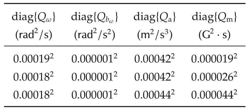
Table 1 Identified sensor noise covariance matrices.
Note the covariance values in Table 1 were identified for a stationary IMU.Under experimental testing(described in Section 6),the sensor noise levels were observed to increase,owing to factors such as hand tremors of the human operator maneuvering the unit.However,the values given led to good estimation performance by the AHRS,and are useful as a starting point for tuning of the covariance levels to match the conditions of the experiment.
2.2 System dynamics
Using the sensor models in Section 2.1 and the nonlinear rotational kinematics=RS(ω),where S is a 3×3 skew-symmetric matrix such that S(x)y=x×y,thecross product(we will also use the properties S(x)y=-S(y)x,S(x×y)=S(x)S(y)-S(y)S(x)and S(Rx)=RS(x)RTin the sequel),and ωis the angular velocity of the body in the body-fixed frame,the dynamics of the AHRS are described by
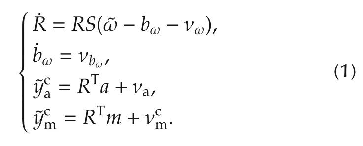
We use the nominal(noise-free)version of(1)as the model of the plant dynamics for the nonlinear observer design.Dropping the c superscript for brevity,the nominal dynamics are written as
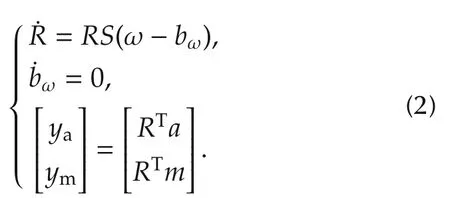
2.3 Geometry of SO(3)
Throughout Section 2,we formulated the attitude of the AHRS unit in terms of rotation matrices R ∈SO(3),where SO(3)is the special orthogonal group of dimension 3.In fact,SO(3)is a Lie group,which provides access to a number of tools from differential geometry,see for instance[23].
Since SO(3)is a Lie group,it is associated to a Lie algebra so(3)and an exponential map exp:so(3)→SO(3).The Lie algebra so(3)is[24,Page 411]

and the exponential map exp is the matrix exponential.In other words,the matrix exponential of skew-symmetric matrices generates members of SO(3).Sincefor R ∈SO(3)close to identity respectively ξ ∈so(3)close to zero,we have the approximations

3 Invariant observer design
In this section,we design an invariant observer for the nominal(noise-free)AHRS system(2).The theoretical background is covered in tutorial fashion in[17]and the source papers[5,6].
3.1 System symmetries

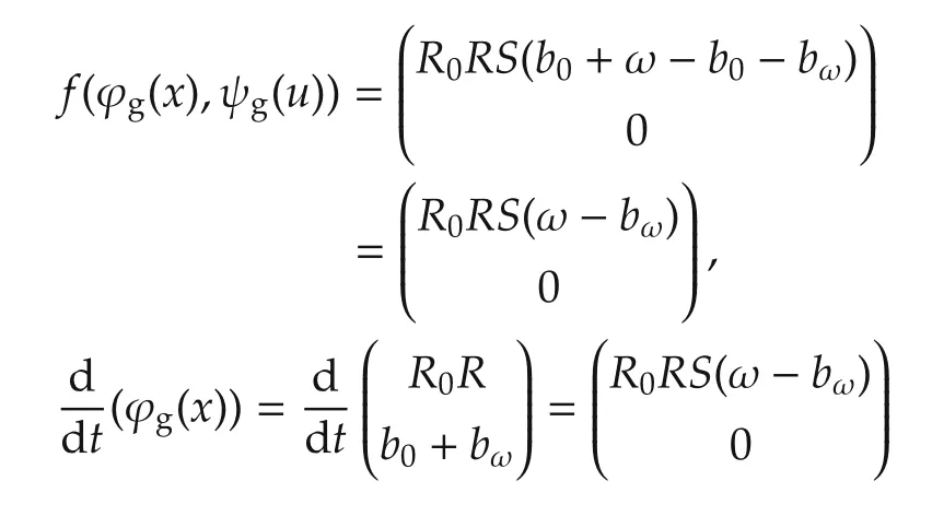
meaning the dynamics(2)are G-invariant w.r.t.ϕg,ψg.Remark that ϕg:G×X →X is Lg,the action of G on itself by left translation;this is relevant for one of the design steps in Section 3.2.
The given Lie group actions induce the action ρg:G×Y →Y on the output equation y=h(x,u)in(2)as meaning that(2)is G-equivariant under the identity action ρg=id.
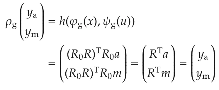
The above set of symmetries ϕg,ψg,ρgphysically represent a constant rotation R0of the ground-fixed frame as well as a constant shift b0of the rate gyro bias bω.This set of symmetries is not unique,for instance a different set of symmetries corresponding to rotating the bodyfixed frame in the AHRS system is used in[17].We will only focus on the given set of symmetries to design an invariant observer in Section 3.2.
3.2 Observer construction
Once the symmetries of a system are known,building an invariant observer is systematic.
First we solve for the moving frame(x)by concatenating the Lie group actions as(where r=dim(G)and m=dim(X)+dim(U)+dim(Y)),then solving=c for g=γ(x).As mentioned in Section 3.1 we are dealing with ϕg=Lg;we thus have=ϕgand setting c=e the global solution is g=γ(x)=x-1=(RT,-bω).
The complete set of(estimated)invariants of G is then given bywhich is partitioned as
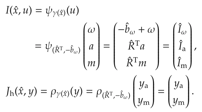
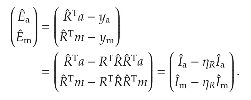
The invariant output error E is

used to construct the invariant observer,whose invariant estimation error η will be and we definesuch that
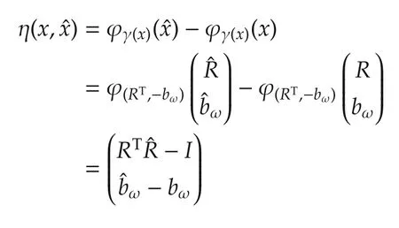
The final component of the invariant observer is an invariant frame(wi(x)),given by
where D is the differential and vi∈TeX are the basis vectors of the tangent space to Xate ∈X.A set of basis vectors for this 6-dimensional vector space is given by
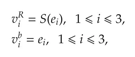
where eidenote the canonical basis of.The invariant frame components are thus
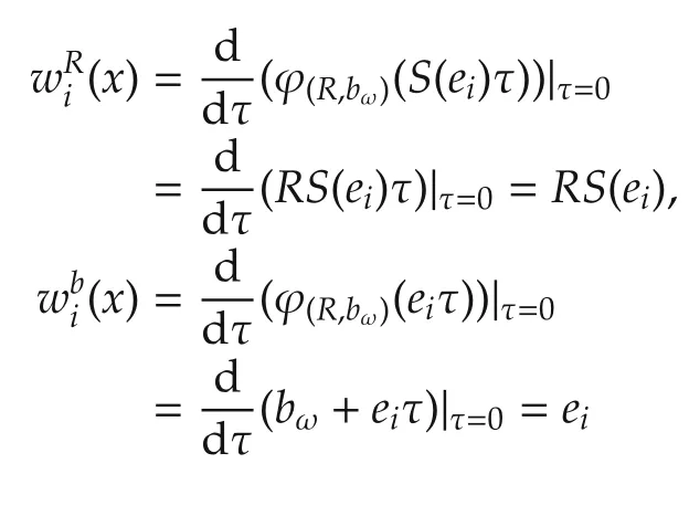
and the invariant observer is written as[5]
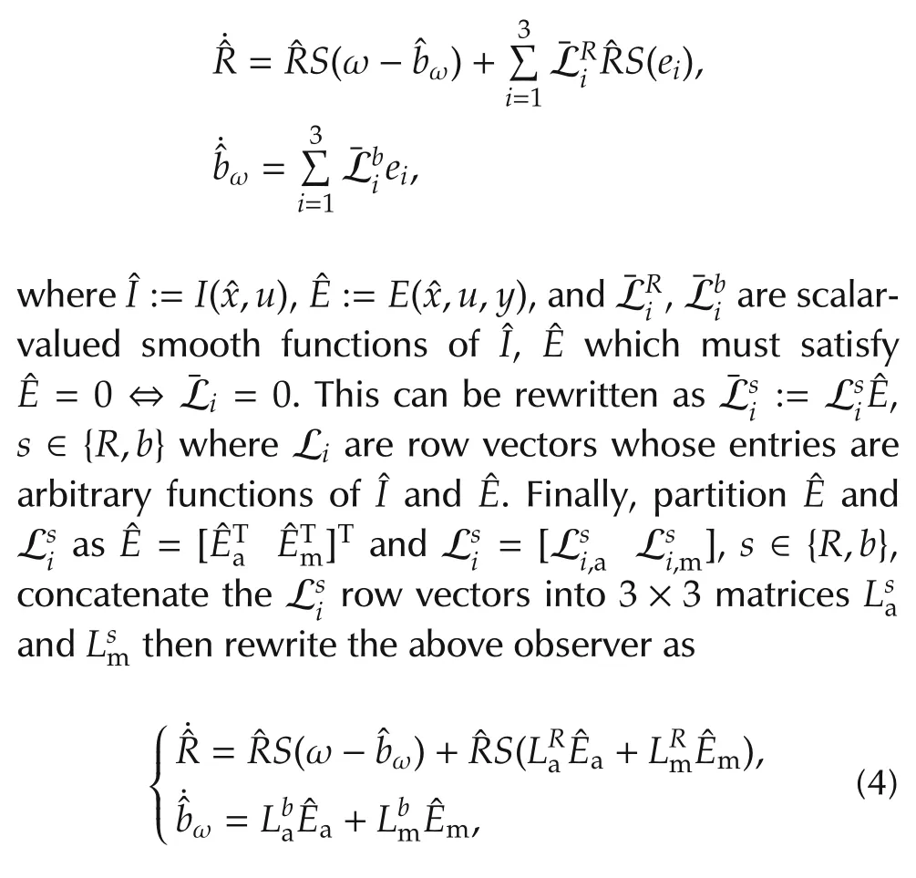
where the entries of each gain matrix L are arbitrary functions ofand.
At this point we have derived an invariant observer(4)and obtained its associated invariant estimation error η.From[5,Theorem 3]we know the dynamics of η satisfy

a remarkable property which says that the estimation error dynamics associated to an invariant observer depend on the system’s trajectory only through its estimated invariants,which simplifies the process of finding gains for(4)to achieve asymptotically stable estimation error dynamics.
The actual form of(5)is obtained by direct calculation.We find

3.3 Gain selection
So far,we have not addressed gain selection of the invariant observer.The goal is to find a set of observer gains in(4)to stabilize the invariant estimation error dynamics(6).Although this task may be simplified by the reduced dependence of(6)on the system’s trajectory,of course it remains difficult due to its non-systematic nature.
A nonlinear observer for the AHRS dynamics(2)which guarantees almost-global stability is given in[4,Theorem 5.1,equation(32)],termed the explicit complementary filter with bias correction.This observer was obtained through a Lyapunov analysis of(2),i.e.,the design is unrelated to the invariant observer methodology;nevertheless,we will show how we can reduce to this form by choice of gains L in(4),demonstrating that[4,equation(32)]is a particular instance of an invariant observer.These L gains will be used as a comparison for the Invariant EKF approach to obtaining gains covered in Section 4.
Return to the invariant observer(4)and employ the following gains:

where kP,kI,la,lm∈R+are user-selected constants and a,m are the gravity and magnetic field vectors as before.Remark we have reduced the tuning degrees of freedom from 4×9=36 to 4.The set of gains(7)meets the condition L=L(,)and so the resulting observer is invariant.Substituting(7)along withinto observer(4)yields

which can be rewritten as

which is precisely[4,equation(32)].This guarantees the almost-global stability of the invariant observer(4)under the choice of gains(7).
4 Invariant extended Kalman filter
The Invariant EKF(IEKF)[9,10,12,13]is a systematic method for computing the gains of an invariant observer.It is based on introducing process and measurement noise terms which preserve the system’s invariance,linearizing the resulting invariant estimation error dynamics(5)about η=e and the estimated invariant,then matching the resulting linear system dynamics with a Kalman filter’s estimation error dynamics.This allows to read off a set of(A,B,C,D)matrices which can be used in a Kalman filter formulation to compute the gain matrices L of the invariant observer.Note the contrast to a conventional EKF,which linearizes the original(noise-containing)system dynamicsabout the nominal estimated trajectory(u),,then applies the Kalman filter to estimate corrections for the estimated stateof the nonlinear system.Because the invariant estimation dynamics being linearized depend on the estimated system trajectory only through the latter’s invariants,the IEKF can reduce or completely eliminate the danger of filter divergence[13,14],a chain of events where a poor trajectory estimate gives a poor linear system approximation for the Kalman filter,leading to an incorrect update of the estimated state of the original system,which provides an even worse linear model approximation for the next Kalman filter pass,and so on until the closed-loop filter becomes unstable.Of course,the increase in robustness against divergence offered by the IEKF depends on the specific example,since it is determined by the forms ofand Υ(η,).In the case where the η dynamics are autonomous,the IEKF is able to guarantee the global stability of the observer under certain technical conditions[13].
We briefly recall the continuous-time Kalman filter,e.g.,[14,Chapter 7].The filter applies to LTV systems

where w and v are process and measurement white noise vectors with covariances Qν=E〈wwT〉,Rν=E〈vvT〉,respectively,and zero cross-correlation:E〈wvT〉=0.The Kalman filter for(8)is

a linear time-varying observer designed to minimize the covariance of the estimation error.From(9)and(8),the Kalman filter’s estimation error dynamicsare

4.1 Linearization
Referring back to Section 2.1,in the presence of sensor noise the AHRS dynamics are(1):
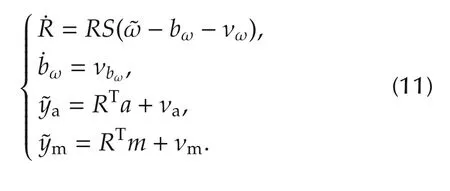
Since the noise vectors νω,νbω,νfand νmare all expressed in the body-fixed frame,they are unaltered by the Lie group actions ϕg,ψg,ρg,since as explained in Section 3.1 the latter physically represent a rotation of the ground-fixed frame.This means system(1)is Ginvariant and G-equivariant just like the nominal system(2).
The invariant observer(4)directly employs the noisy measurementsand is thus written

where

We now compute the dynamics of the invariant estimation errorsobtained in Section 3.2 using the noise-containing system.We find
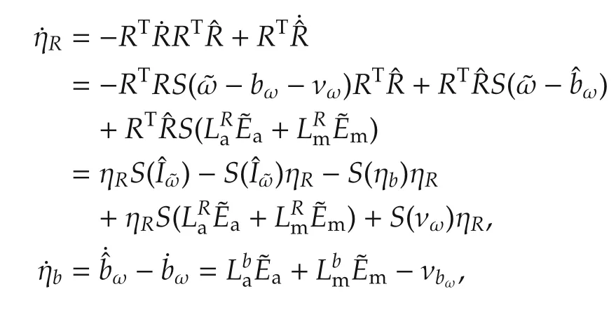
We will linearize the above dynamics about ηR=I,ηb=0,i.e.,zero estimation error.For the former,since ηR∈SO(3)is close to identity,we use(3)from Section 2.3 to write


Meanwhile for ηbwe have

an exact relationship because the Lie algebra ofis[23,Page 192]such that the exponential map is identity.Linearization about ηR=I,ηb=0 thus corresponds to taking thevectors ζRand ζbas close to zero.We first linearize the output error termseach written as.We obtain
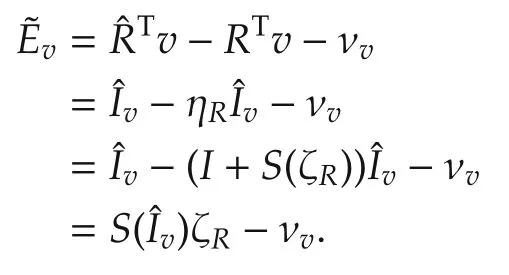
Recall the ηRdynamics:
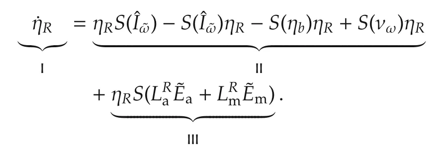
We have
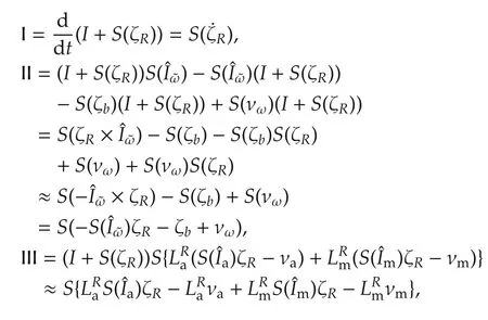
where quadratic terms S(ζb)S(ζR), S(νω)S(ζR) and S(ζR)S(ζR)are neglected as being small.The linearized ηRdynamics are thus

The ηbdynamics are

which linearizes to

The ζR,ζbdynamics can now be written in form(10)as
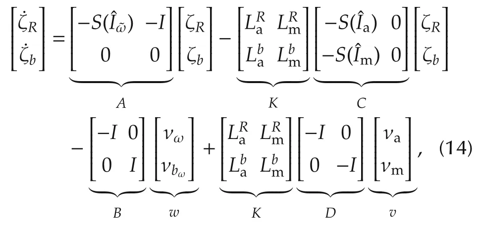
which yields the set of matrices(A,B,C,D)used in(9)to compute the observer gains L through the Kalman gain K.
5 Extended Kalman filter
For purposes of comparison,we will also derive a conventional EKF design for the AHRS.The operation of this filter was described in Section 4.
Linearizing the noise-containing system dynamics(1)about the estimated trajectoryusing a first-order Taylor series approximation results in an LTV system with error states.The first of these terms is problematic,becausebut.Because of this,we instead introduce a multiplicative attitude error,such that.Referring to Section 2.3,forclose to I we have the linearizing approximation

The(A,B,C,D)matrices of the LTV system dynamics are now obtained by direct computation employing(1)and(2).Note that

and take the time derivative of(15):
We also find

and for v ∈{a,m},the linearized outputis
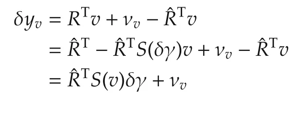
such that the LTV system used by the conventional EKF is
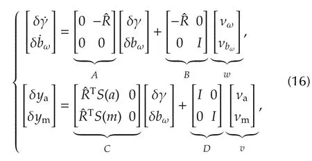
where w and v are the process and measurement noise vectors identical to(14)in Section 4.1.
The matrices(A,B,C,D)in LTV system(16)can be used directly with the continuous-time Kalman filter equations(9)given in Section 4.However,the standard practice in conventional EKF designs is to first discretize(16),then apply a discrete-time Kalman filter to the result,e.g.,[3].The advantage of this approach is that the discrete-time Kalman filter contains a difference equation for the covariance matrix Pk,which can be computed algebraically as opposed to numerically integrating the Riccati equation governing P in the continuous-time Kalman filter.
Irrespective of which version of the Kalman filter is used,the output is the estimated error state[δγ δbω],which is used to update the current state estimate,obtained from numerical integration of the nominal state dynamics(2),toas

6 Experimental testing
6.1 Implementation details
The invariant AHRS observer is given in(4).The observer gains L are provided as the constants(7).Based on experimental tuning,we chose the gain values kP=2.5,kI=0.1,la=0.02 and lm=50,which as explained in Section 3.3 guarantee almost-global stability of the estimation error dynamics.Some guidance regarding tuning of the invariant observer gains is given in the source article[4]for(7),which employs values kP=1,kI=0.3 for experimental testing and notes that laand lmact as weights on the confidence in the accelerometer and magnetometer readings,respectively.The final choice of values was obtained from hardware experiments(covered in Section 6.2)by inputting logged sensor data into an offline version of the observer,then manually tuning its gains to match the computed estimates against the measured ground truth.
For the Invariant EKF,the gains L are computed from matrices K and(A,B,C,D)in(14)substituted into the Kalman filter equations(9),where the noise covariance matrices Qν=blkdiag(Qω,Qbω)and Rν=blkdiag(Qa,)are available from Table 1 in Section 2.1.
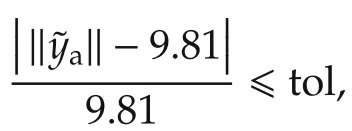
The invariant observer is numerically implemented using the modified Euler method running at 100 Hz,the sampling rate of the IMU.We employ a complementary filter structure[3,Chapter 5]:the estimated dynamics(d/dt)=f(,)in(4)are integrated at the full 100 Hz rate to obtain rough estimates of,while the observer dynamics in(4)are integrated at a lower aiding rate(here chosen as 25 Hz)using the output measurementsa,mand updating the estimated state.The 25 Hz rate is the same as the one used in[4]for experimental validation;it was also found that overly low aiding rates(≤5 Hz)would destabilize the Modified Euler numerical integration method.The complementary filter approach provides the following important feature:as discussed in Section 2.1,we have assumed that the accelerometer outputameasures the gravity vector,which does not hold whenever the AHRS unit undergoes linear accelerations.To mitigate this,we test each accelerometer measurement by computing the norm‖a‖and comparing it to‖g‖=9.81 m/s2,considering the data as reliable if where tol >0 is a unitless tolerance factor selected by the user.An overly low tolerance will not perform well in experiment due to noise and time-varying bias affecting the measurement;we have found tol=0.5 works well in practice.Ifais outside the prescribed tolerance,accelerometer aiding is omitted at that time step,but gets re-established as soon as the measurement is again within tolerance.Note that the magnetometer measurementsmdo not need to use a rejection criterion,and so are used for aiding irrespective of the accelerometer validity.
The conventional EKF design is also implemented using a complementary filter topology.Whenever an aiding measurement is available,the LTV system matrices(16)are evaluated at the latest state estimate,followed by running a(discrete-time)Kalman filter as described in Section 5.For fairness of comparison,the conventional EKF employs the same aiding rate and accelerometer tolerance as the invariant observer,and the same noise covariance matrices Qν,Rνas the IEKF.
During an initialization phase where the system is stationary,we compute running averages of the rate gyro,accelerometerand magnetometersignals.Thevector is then used to calculate the initial yaw angle w.r.t.magnetic north as

where cφ=cos φ0,etc and φ0,θ0are the roll and pitch angles of the body during initialization,e.g.,φ0=θ0=0 for a level configuration.The set of Euler angles(φ0,θ0,ψ0)is used to build the initial estimated attitude

The ground-fixed magnetic field vector is then m =.Using the sensor models in Section 2.1 we have

providing the initial estimated biasω(0)=bω0.We also have

used in the accelerometer output model=a-ba0.
An indoor optical motion capture system was employed to acquire a ground truth for the motions of the AHRS unit.The system uses eight Vicon Bonita 3 cameras with near-infrared strobes to illuminate and track the motion of reflective markers attached to the surface of the AHRS unit.The associated Tracker software estimates and displays the pose of the rigid body defined by the set of markers in real-time,providing millimeterlevel precision in translation and sub degree-level precision in rotation measurements.
6.2 Experimental results
The hardware experiment consists of the following sequence of actions:the AHRS unit starts out stationary on a level surface,and a running average of its inertial sensor readings is used to initialize the filter as described in Section 6.1.The unit is then picked up by hand,and executes a sequence of two back-and-forth roll(i.e.,rotations about the longitudinal axis)motions,followed by two back-and-forth pitch motions and two back-and-forth yaw motions.After this,the unit is violently shaken in all directions while maintaining an approximately level configuration,in order to introduce large lateral accelerations to act as an unmodeled effect in the accelerometer outputa,c.f.Section 2.1.After this shaking phase,another sequence of back-and-forth roll,pitch and yaw motions is executed,followed by a second shaking phase.The unit is then set down.The list of events and their corresponding times are listed in Table 2.
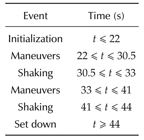
Table 2 AHRS hardware test intervals.
In order to compare performances,the IMU data logged during the experiment was run through offline versions of the three AHRS filter designs(nonlinear invariant observer,invariant EKF,conventional EKF).Of course these filters are causal and can be run in real time,and require only a minimal amount of computing power as seen from the observer equations in Sections 3 to 5.Timing the offline filter implementations in MATLAB running on a low-end laptop system,the experimental data was processed in 1.10 s,1.28 s and 1.63 s for the invariant observer,invariant EKF and conventional EKF,respectively.The conventional EKF’s longer runtime is due to the discretization of LTV system(16)at every aiding instant,as discussed in Section 5.The Vicon optical motion-capture system was used during the experiment to obtain independent measurements of the motions of the unit,which are used as a high precision ground truth for the attitude estimates from the AHRS designs.
The AHRS estimation results of attitude∈SO(3)and rate gyro biasω,the former converted to the ZYX roll-pitch-yaw Euler angle sequence(φ,θ,ψ)and plotted against the Vicon-provided attitude,are shown in Fig.1 for the invariant observer,Fig.2 for the invariant EKF,and Fig.3 for the conventional EKF.Note the vertical grid lines in the plots correspond to the time intervals listed in Table 2.
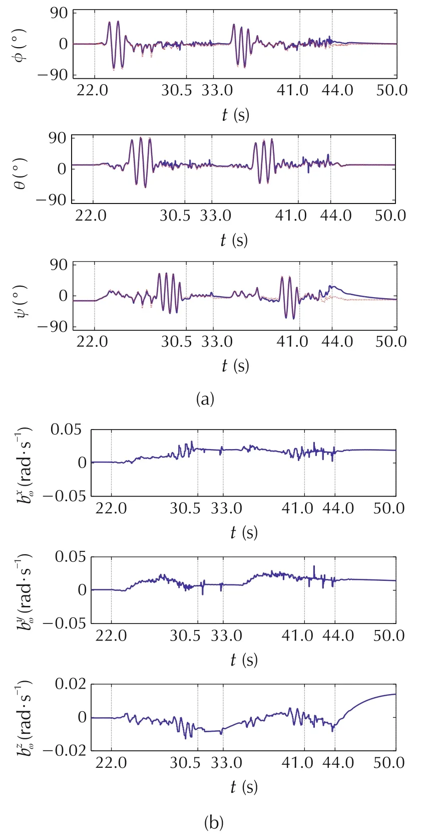
Fig.1 Invariant observer.(a)Estimated attitudes.(b)Rate gyro biases.
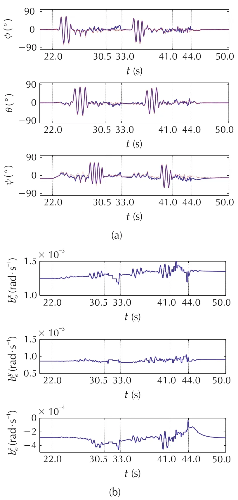
Fig.2 Invariant EKF.(a)Estimated attitudes.(b)Rate gyro biases.
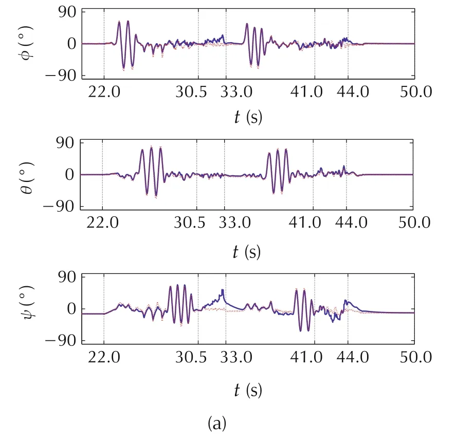
From Figs.1-3,we see that the estimated attitudesqualitatively agree with the Vicon-derived attitude ground truth during the two maneuvering phases,and(as expected)are perturbed away from the ground truth during the shaking phase,although this is partially mitigated by the accelerometer measurement rejection criterion discussed in Section 6.1.The estimates of yaw exhibit the largest error across all three designs,which is due to this degree of freedom relying on magnetometer aiding measurements,which exhibit a much lower signal-to-noise ratio than measurements from the accelerometer.Once the second shaking phase ends at t ≥44 s and the AHRS unit is set down,the estimated attitudes re-converge to the ground truth,which shows the three observer designs are correctly implemented and tuned.
The rate gyro bias estimatesωfrom the three designs do not have a ground truth available,so their accuracy cannot be verified directly.We see the estimated biases for the invariant observer exhibit much larger variations than the other two designs.Also,by comparing the attitude and bias estimates,we see a correlation between rapid changes in individual rate gyro bias estimates and errors in their corresponding attitude Euler angles.
In order to quantitatively assess the differences in estimation performance between the three designs,the RMS values of the errors between the estimated and ground truth attitude Euler angles are given in Table 3,broken out by the experiment phases listed in Table 2 and the observer design.For reference,the attitude estimation errors for all three designs are plotted in Fig.4.
Table 3 Estimation error RMS values.
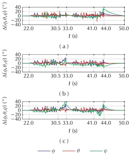
Fig.4 Attitude estimation errors.(a)Invariant observer.(b)Invariant EKF.(c)Conventional EKF.
Using Table 3,we first compare the performance of the invariant observer to the invariant EKF.We see that the invariant observer performs on average better(lower RMS errors)than the IEKF during the first three phases—maneuvers,shaking,and second maneuvers—while the IEKF performs better in the last two phases—second shaking and set-down.An explanation is that the IEKF is a time-varying observer,so its internal gain K requires some time to converge to a proper level,whereas the Invariant Observer gains were tuned a posteriori to provide good results with the logged data,as explained in Section 6.1.This is reinforced by the fact that the sensor noise covariances listed in Table 1 in Section 2.1 were identified for a stationary IMU,whereas the noise levels in the logged sensor data were observed to increase significantly when the unit was in motion.This was likely caused by the tremors created by the human operator when maneuvering the AHRS unit by hand.
A more direct comparison can be made between the IEKF and conventional EKF,since both filters employ an identical tuning of process Qνand output Rνnoise covariance matrices,plus initial estimation error covariance matrix P(0).Here,the IEKF performs better than the EKF,specifically during the two shaking phases at 30.5 ≤t ≤33 s and 41 ≤t ≤44 s.Because all the tunable parameters are identical between the two designs,this improvement in performance can be explained by the IEKF’s reduced dependence on the estimated system trajectory,which can be seen by comparing the IEKF’s linearized model matrices(14)in Section 4.1(with invariantsgiven in Section 3.2)against the conventional EKF matrices(16)in Section 5.As explained in Section 4,this feature reduces the problem of poor state estimates leading to poor updates by the Kalman filter,which is particularly important during periods of model uncertainty such as here.A different example of IEKF superiority over a conventional EKF during periods of model uncertainty—the take-off phase of an outdoor helicopter UAV—is demonstrated in[17].A recent demonstration of the advantage of an invariant EKF over a conventional EKF in a commercial inertial navigation system is given in[25].
7 Conclusions
This article considered the design of an AHRS,a simple example of a nonlinear state estimator for aided inertial navigation,using three approaches:an invariant observer with a nonlinear stabilizing gain design,an invariant EKF,and a standard EKF included for comparison purposes.The design details of each were covered in order to explain the workings of the invariant(symmetrypreserving)estimation methodology.The three designs were implemented and tested on a common set of experimental data,and the resulting attitude estimates were compared and quantified against a high-precision ground truth from an optical motion capture system.This testing demonstrated the successful performance of all three designs in challenging experimental conditions,and highlighted the advantage of the invariant EKF over a conventional EKF in cases of model uncertainty.The Invariant EKF design methodology is both systematic and ideally suited for estimation dynamics evolving on Lie groups,which are widely found in systems such as UAVs and robotics.This makes it a worthwhile tool to learn and apply for practitioners working in these fields.
Acknowledgements
The experimental data for this article was obtained at the University of Alberta’s Applied Nonlinear Controls Lab.The author thanks Nikos Vitzilaios and Romeo Tatsambon for their assistance in running the hardware experiments.
杂志排行
Control Theory and Technology的其它文章
- Parallel loop recovery with quiescent compensation for high performance feedback control of systems with imperfect actuators
- Nonlinear observer-based control design and experimental validation for gasoline engines with EGR
- On the mechanism and control for the ultra-low frequency oscillation in NY Power Grid with large-scale hydropower
- Guaranteed feasible control allocation using model predictive control
- Diagnosability of a class of discrete event systems based on observations
- Optimal finite-dimensional spectral densities for the identification of continuous-time MIMO systems
