Nonlinear observer-based control design and experimental validation for gasoline engines with EGR
2019-07-26WeihaiJIANGTielongSHEN
Weihai JIANG,Tielong SHEN
Department of Engineering of Science,Sophia University,Chiyoda-ku Tokyo 102-8554,Japan
Received 3 October 2018;revised 21 November 2018;accepted 21 November 2018
Abstract This paper presents a nonlinear observer-based control design approach for gasoline engines equipped with exhaust gas recirculation(EGR)system.A mean value engine model is designed for control which includes both the intake manifold and exhaust manifold dynamic focused on gas mass flows.Then,the nonlinear feedback controller based on the developed model is designed for the state tracking control,and the stability of the close loop system is guaranteed by a constructed Lyapunov function.Since the exhaust manifold pressure is usually unmeasurable in the production engines,a nonlinear observer-based feedback controller is proposed by using standard sensors equipped on the engine,and the asymptotic stability of the both observer dynamic system and control dynamic system are guaranteed with Lyapunov design assisted by the detail analysis of the model.The experimental validations show that the observer-based nonlinear feedback controller is able to regulate the intake pressure and exhaust pressure state to the desired values during both the steady-state and transient conditions quickly by only using the standard sensors.
Keywords:Engine,exhaust gas recirculation(EGR),Lyapunov design,stability,observer-based stabilizing control
1 Introduction
To meet the increasingly stringent emissions and fuel economy regulations for automotive industry,the cooled external exhaust gas recirculation(EGR)has been gradually considered as a mainstream technology to reduce the fuel consumption of gasoline engine powered vehicles[1-3].However,the air dynamic system of the engine will be cross-coupled and become more nonlinear and complicated when the cooled external EGR is introduced into the air system,and lead to a very difficult dynamic control problem of engine[4].
Various control approaches have been proposed to attempt to solve the challenging problem.In the proposed approaches,usually intake mass flow and intake manifold pressure are prefer to be selected as the control outputs[5-7]for their measurability and convenient of application.A.Ejiri et al.[5]adopted a disturbance observer based MIMO/SISO(multi-input multi-output/single-input single-output)switchable control approach for the VGT-EGR system by using intake manifold pressure and compressor mass flow as the control outputs.H.Xie et al.[6]proposed a disturbance rejection based decoupling control framework of intake manifold pressure and compressor mass flow.
However,the exhaust manifold is directly connected with the EGR valve,as a result,the exhaust manifold pressure has a more fast and significant influence on the EGR dynamic.There are also many literatures[7-10]would like to consider the exhaust manifold pressure as the control outputs despite the fact that the measuring of the exhaust manifold pressure in the production engines is prohibitive.J.Wahlstrm and L.Eriksson[7]investigated the impacts of output selection for the air system control of diesel engines,and found that compared with model predictive control(MPC)based intake manifold pressure and compressor flow control,choosing EGR ratio and the differential pressure of exhaust manifold pressure and intake manifold pressure as outputs has both performance improvements and benefits of handling unreachable set points.The research from[9]obtained the conclusion that the control of the intake manifold pressure and exhaust manifold pressure,which is transformed from the engine performance,is vital important to achieve a satisfactory dynamic control performance of the air system.
However,equipping the exhaust manifold pressure sensor in the production engines is also unacceptable since the high cost and poor durability of the physical sensor.Many studies have investigated different approaches of exhaust manifold pressure estimator to try to remove the cost-prohibitive sensor.K.Siokos[11]proposed a physics-based exhaust manifold pressure estimator by introducing an intake oxygen signal for a turbocharged gasoline engine with low pressure EGR.J.Lee et al.[12]designed a nonlinear sliding mode observer by adopting a simplified incompressible constriction flow modeling of EGR valve.R.Salehi et al.[13]proposed a second-order sliding-mode observer to estimate the exhaust manifold pressure of turbocharged gasoline engines with avoiding the chattering of the system.S.Kim et al.[14]developed a sliding mode observer for the dual loop EGR and VGT system of a diesel engine by coupling a static regression model of intake compressor flow and turbine outlet flow.
However,most of the works on air system dynamic control by selecting the exhaust manifold pressure as the output,either directly use the measuring exhaust manifold pressure as the feedback variable,which is usually unacceptable in the production engine,or is lack of a stability consideration for the close loop system by coupling the exhaust manifold pressure modeling.
To handle this challenge issue,in this paper,the nonlinear observer based stabilization control scheme is proposed to achieve the stabilizing control of the dynamic of the EGR system with guaranteeing of the stability of the close loop system and without depending on the measuring exhaust manifold pressure signal.The observer-based nonlinear feedback controller assisted by a Lyapunov design is used to guarantee the asymptotic stability of the close loop dynamic system.Also,the experimental validations have demonstrated to evaluate the effectiveness of the proposed control scheme.
The organization of this paper is as follows.The control-oriented modeling for the gasoline engine is introduced in Section 1.In Section 2,the proposed control scheme based on the developed model are discussed.Also,nonlinear feedback controller design and the corresponding close loop stability analysis are given.Moreover,the nonlinear observer-based controller design and the corresponding close loop stability analysis are elaborated.In Section 3,experimental validations are presented.Finally,conclusions and remarks are made.
1.1 System modeling
In this research,the target engine is a four cylinder gasoline engine,which is a high efficiency Atkinson cycle engine equipped in the third generation of prius vehicle for hybrid application[15].As shown in Fig.1,the engine is equipped with EGR and retarded intake valve closing timing(VVT)system.
However,unlike the traditional engine,the EGR pipe is connected directly with intake port of the engine in this research.Moreover,the exhaust gas is guided directly to the intake port from the exhaust manifold for each cylinder without mixing dynamic with the fresh air in the intake manifold.Even if there may exist some mixing near the intake valve,the exhaust gas will also be pushed into the cylinder by the intake manifold air at each cycle.Thus a assumption can be made that the EGR gas can always be inducted into the cylinder from the EGR valve and the dynamic of the exhaust gas in the intake manifold can be neglected.
For the convenient of model design,the system main variable schematic of the air system is described in Fig.2.Here p,,T,u denote the pressure,charge mass flow,temperature and control input variables of the air system respectively,while the specific subscripts corresponding to each specific physical variables.To simplify the model for control,the intake and exhaust manifold are regarded as two uniform control volume.And the temperature states only have minor effects on the system properties[16],which is also neglected.
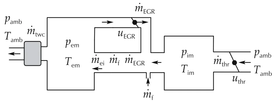
Fig.2 The simplified air system schematic of the engine.
Then,the dynamic model can be described with the following equation by adopting the mass conservation law and the ideal gas equation with concentrating on the two uniform control volume.

where R and V denote the gas constant(J/kg·k)and volume(m3)with the specific intake manifold and exhaust manifold subscripts.
According the fact that there is almost no mixing between fresh air and EGR in the intake manifold,then the EGR mass flow from the EGR valve can be assumed to equal to the EGR mass flow aspirated into the in-cylinder.
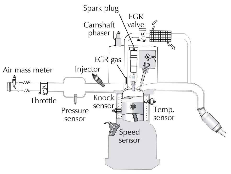
Fig.1 The system structure of the engine.
The EGR mass flow model adopts an incompressible turbulent equation[17].
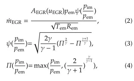
where AEGRis the equivalent orifice area of the EGR valve,which lumps the flow efficiency and can be approximated by a polynomial function.γ is the specific heat ratio of exhaust gas.
Similar to the EGR valve mass flow model,the throttle mass flow model can be written as the following based on the incompressible turbulent model principle,
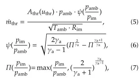
where pamband Tambare the pressure and temperature before throttle valve and approximately equals to the atmosphere state.Athris the equivalent orifice area of the throttle valve,and γais the specific heat ratio of fresh air.
The following in-cylinder mass flow model is a model to describe the equivalent charge inducted into the incylinder in a mean value sense[18],

where the volumetric efficiency ηvdepending on the engine speed Neand intake manifold pressure pim,which can be calibrated by a function of pimand Ne.
The mass flow passing from exhaust manifold into atmosphere through the three way catalyst(TWC)is modeled by an incompressible turbulent restriction model[17],

where Ctwcis the flow coefficient of the TWC.
Then,the EGR fraction in the in-cylinder is calculated as

The effective torque model τe[17,18]is a algebraic sum of the gross indicated torque τig,the pumping torque τp,and the friction torque τfric,which is formulated into the following:

The gross indicated torque is assumed as an ideal Otto efficiency[18]with an empirical EGR ratio correction factor,

where reis the compression ratio of the engine,ηEGR(xEGR)lumps the efficiency loss from the ideal efficieny of Otto cycle,for example,heat transfer and the EGR effects on the efficiency.
The pumping torque is modeled by a simplified description of intake and exhaust manifold pressure[17],

The friction torque is modeled as an empirical polynomial function relative to the engine speed[18],

where Ne,N=Ne/1000,C1,C2and C3are parameters to be calibrated.
Then,the brake efficiency model ηbcan be formulated into:

2 Control design
The control objective of the air system dynamic control is to regulate the engine system dynamics to a desired set point where the maximal brake efficiency can be achieved while the demand torque from the driver’s requirement should also be tracked.Here,in this research,the optimal setpoint of the maximal efficiency at the demand engine speed and torque condition is transformed into the optimal state setpoint of intake manifold pressure and exhaust manifold pressure instead.Since the exhaust manifold pressure usually is unmeasurable in the production engines.The control objective becomes to coordinate uthrand uegrin order to achieve the stabilizing tracking control of the desired intake pressure(pim)and exhaust pressure(pem)without depending on the physical exhaust manifold pressure sensor.
Fig.3 illustrates the general framework of the proposed nonlinear observer-based stabilization control scheme,which includes the optimal equilibrium point decision,nonlinear observer and on-line nonlinear feedback control blocks.
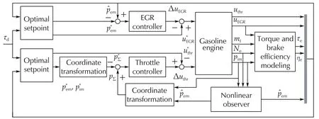
Fig.3 The control scheme of the nonlinear observer-based control.
2.1 Optimal equilibrium points decision
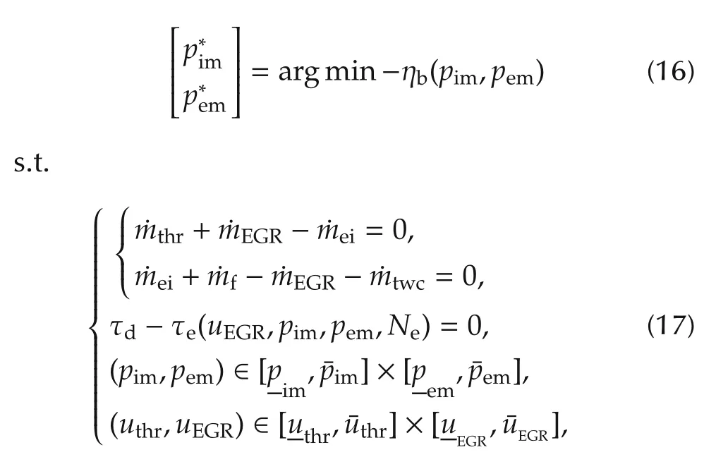
The optimal equilibrium points of optimal states and control inputs at the steady conditions of maximal brake efficiency with torque constraint can be obtained by solving the following formulated stationary optimization problem:
2.2 Feedback control law
In this section,the nonlinear feedback controller is designed based on the dynamic modeling of(1),here the nonlinear feedback control law is designed to try to track of the optimal equilibrium point ofwith guaranteeing of stability under transient conditions.According to Section 1,the dynamic model of(1)is written as follows:
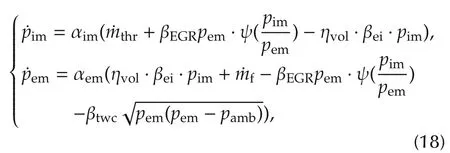
where
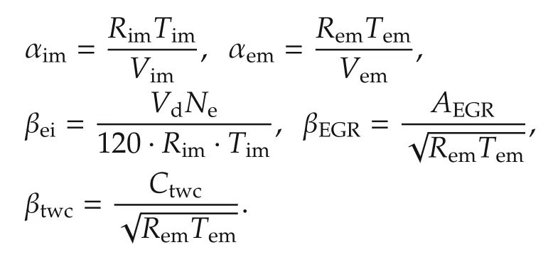
It can be noted that the control inputs uthrand uEGRcoupling into the orifice mass flow model of equation(2)and(5)with two parts structure.Then,for the convenient of obtaining the control inputs when designing the controller,the EGR and throttle mass flow model in equation of(18),are redefined as follows,where the orifice mass flow models are separated into control input part and state part.

One thing can be noted in the pimstate model of(18)before the controller design is that both the throttle and EGR valve have a direct control influence on the intake manifold pressure state.To decouple the state modeling,and make it better for the controller design,the following coordinate transformation is made.The original state coordinate[pim,pem]is transformed into(21).

Then,substitute the new coordinate(21)into the modeling(18),a new dynamic system is obtained:

The given desired equilibrium pointcan be transformed intowith the similar principle of the coordinate transformation.
To construct the error dynamic system for controller design,the tracking error of the pΣand exhaust manifold pressure pemare defined as eΣ:=pΣ-and eem:=pem-.
Then,the sigma error and the exhaust manifold pressure error dynamic system can be formulated as

Proposition 1For any given equilibrium point of intake manifold pressure and exhaust manifold pressure of,if the feedback control law is designed as follows:

then,the closed loop system of(23)coupling with the designed control law is asymptotic stable at the equilibrium point offor any positive control gains of K1and K2.
ProofSubstitute equation(24)into the eΣof equation(23),then we can formulate the new sigma error dynamic function as

Similarly,substitute equation(25)into the emof equation(23),we can get the following new exhaust manifold pressure error equation.

Hence,we can finally formulate the error dynamic function as

The stability of the control error dynamic system can be guaranteed by the Lyapunov stability theorem,here the constructive Lyapunov function is designed as

The derivative of the Lyapnov function,the following equation can be obtained:

As mentioned in Proposition 1,the control gains K1and K2are positive,then we can conclude that forthe Lyapunov function V is positive definite andis negative definite.According to the Lyapunov stability theorem[19],the error system(eem,eΣ)will converge to zero asymptotically over time.That means the tracking error of the intake manifold pressure and the exhaust manifold pressure will converge to zero with time by using the Lyapunov control design based control law. □
2.3 Observer based nonlinear feedback controller design
To replace the exhaust manifold pressure sensor,the nonlinear observer is designed by the following form:
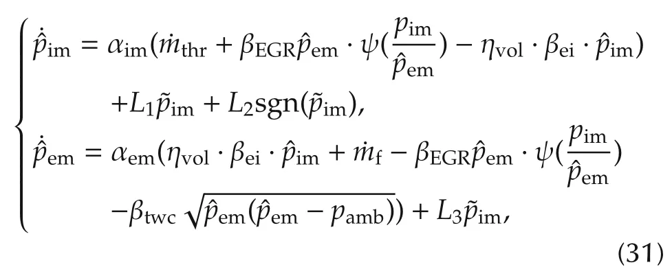
Similar with coordinate transformation of feedback controller design part,here the state coordinate(pim,em)can be transformed into[Σ,em]=[pim+em·αim/αem,em].Then,substitute the new coordinate into the modeling of(31),the new dynamic system is obtained:
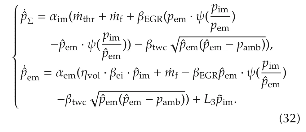
And let


Let

Then,the error dynamics of pemcan be obtained:

Finally,the tracking error dynamics and the observer error dynamics is summarized as
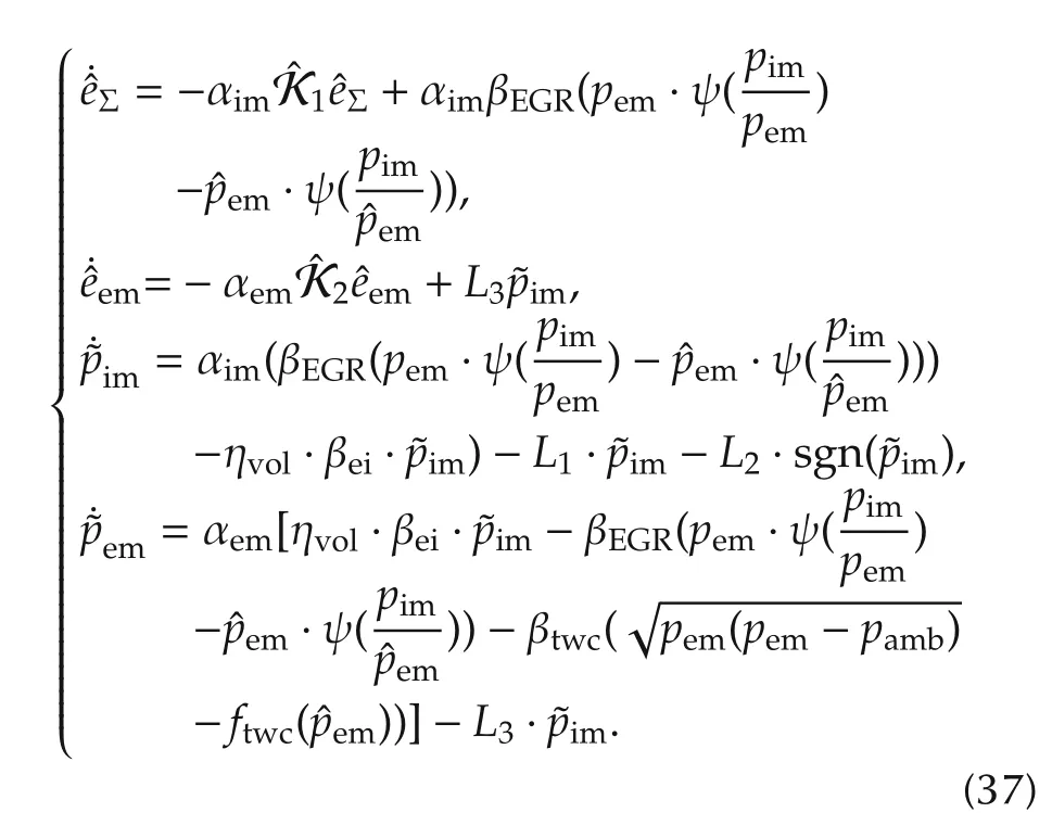
To stabilize control the intake pressure and exhaust pressure states based on the proposed observer during the load step conditions,a nonlinear feedback controller is needed to be designed to stabilize the error dynamics(37).That means the control gainand the observer gain L1,L2and L3need to be designed to guarantee both the tracking error and the observer error asymptotically convergent to 0.
Proposition 2For the given, if the observer-based feedback control law is designed as,

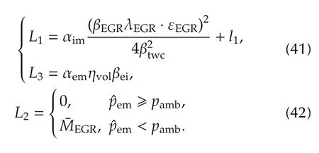
then,the closed loop system of(37)is asymptotic stable at the given equilibrium point ofby adopting the control law of(38)and(39),if the, control gainsandsatisfy the inequality of(40),
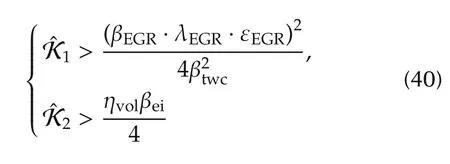
and the observer gains satisfy the following equality:
ProofTo prove the proposed Proposition 2,the candidate Lyapunov function is designed as

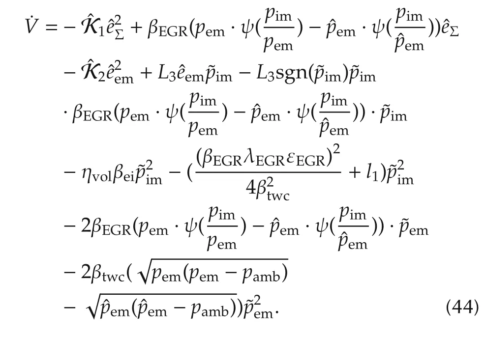
The derivative of the Lyapunov function candidate can be derived as into
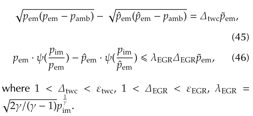
The equation of(45)and(46)can be formulated in the following form:
Substitute equalities(45)and(46)into inequality(44),the differential of the Lyapunov function can be further obtained as follows:
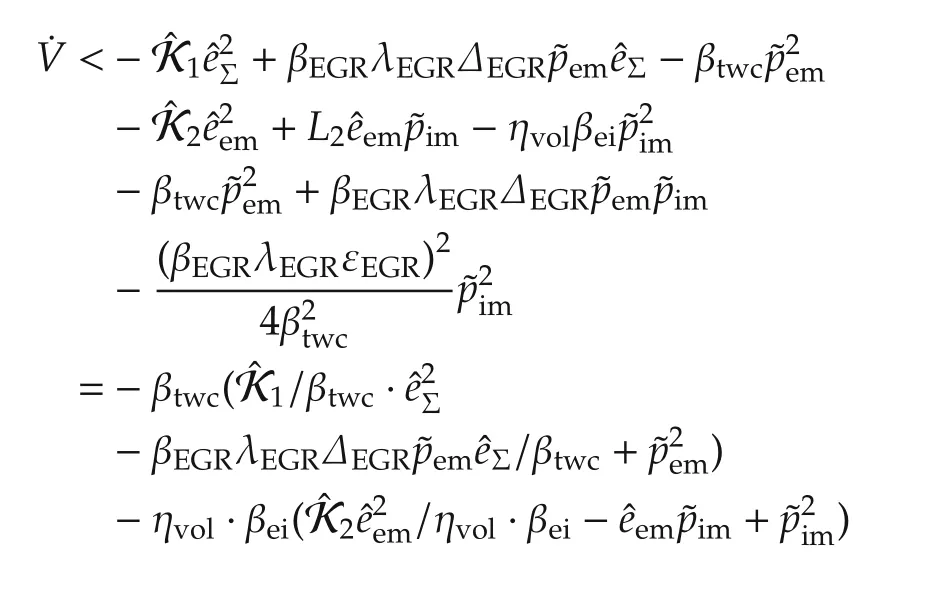

Substitute equations(40)-(42)into(47),the inequality of the derivative of the Lyapunov function candidate in(48)can be guaranteed,
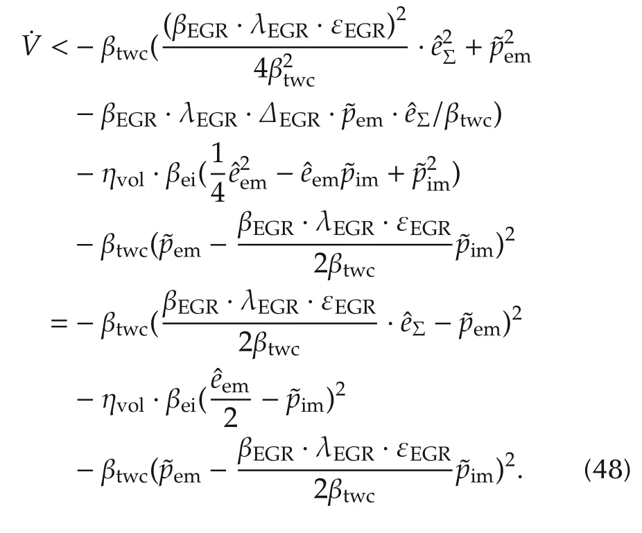
Based on the analysis,we can conclude that V(0)=0,0 and.Therefore,the tracking error and the estimation error of the observer can converge to zero asymptotically.In other words,the intake pressure and exhaust pressure observer are able to converge to the corresponding true values with time,which can also be controlled converge to the desired optimal equilibrium point.
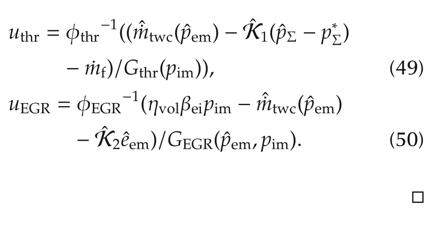
Finally,the nonlinear feedback control law is designed as
3 Experimental validation
In this section,the experimental validation results of the proposed control scheme are evaluated and analyzed.The experimental validations were conducted on a state-of-art spark-ignition engine test bench,and the detail technical parameters of the engine are listed in Table 1.
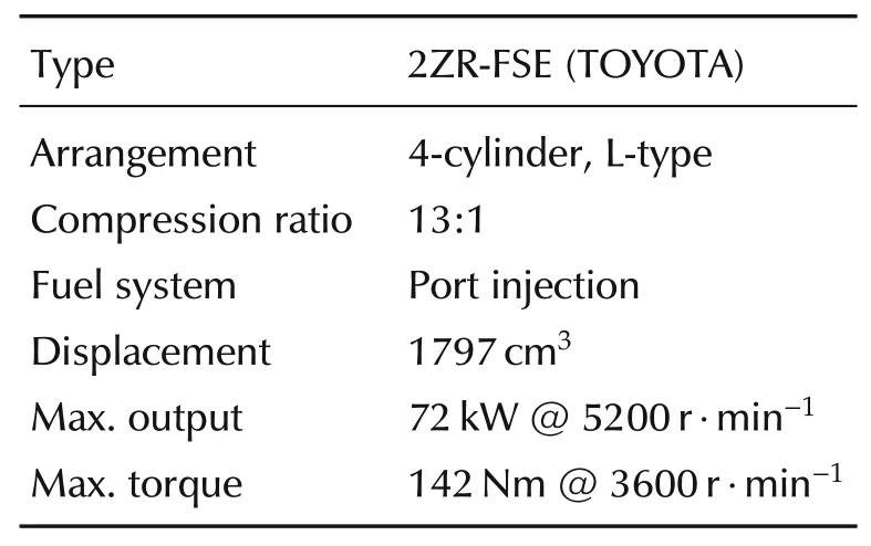
Table 1 The specifications of the engine.
3.1 Test bench
The system structure of the test bench is shown in Fig.4.
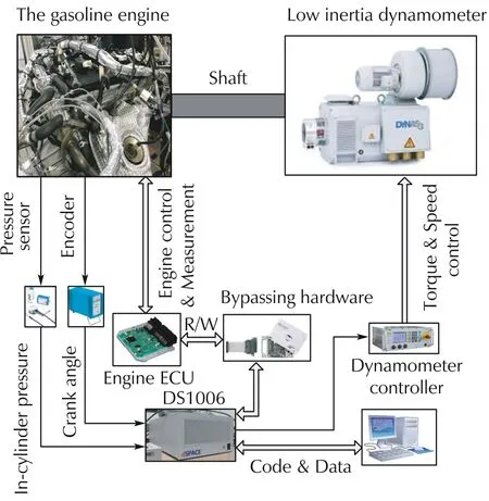
Fig.4 The engine test bench.
In this test bench,the four cylinder 2ZR-FSE engine[15]is connected with an low-inertia alternating-current(AC)electrical dynamometer,which can emulate the external load torque and measure the output effective torque of the engine in real time.The senor and actuator signals from the engine can be measured and collected by the prototype ECU,while the real time control system dSPACE 1006 can read the whole signals and overwrite the algorithm of the prototype ECU through the bypass connection between the prototype ECU and dSPACE.What is more,some other sensors are equipped for the convenient of research like the cylinder pressure sensor and exhaust manifold pressure sensor,from which the signals can also be collected by the dSPACE 1006.Hence,all the data collection and control programming are integrated in the controller of dSPACE,and the control algorithm can be programmed and download into dSPACE by Matlab on the PC to control any channels of the engine through the enable of the control channel of the prototype ECU.
3.2 Controller validation
During the experiment validations,the proposed control scheme only focus on the EGR and throttle control channels.The other engine conditions are controlled as followings,the engine speed is controlled by the dynamometer at 1600 r·min-1,the water and oil temperature are controlled at 87°C and 90°C,respectively.While the spark advance and the fuel injection are controlled at MBT and stoichiometric air fuel ratio by the by-pass ECU according the engine conditions.To be mentioned,the spark advance and air fuel ratio can be controlled by the existing control approach like[20,21]and[22],which is out of the scope of this research.
First,the nonlinear feedback controller of(24)and(25)was validated by the experiments.As shown in Fig.5,the control results at different tuning gains of the controller have been demonstrated,which are designed as K1(0.25,0.45),K2(0.35,0.45)and K3(0.45,0.45)respectively based on Proposition 1 to guarantee the stability of the close loop system.It can be observed when the torque reference is given from 50 Nm to the 55 Nm at the 8th second,the corresponding optimal equilibrium point block in Fig.3 gives a optimal pimand pemreference,then the designed controller will regulate the state to the desired value by controlling the EGR and throttle valve according to the designed control law of(24)and(25).
It can be also noted that the system states of pimand pemcan converge to the designed equilibrium point during the transient condition of load up condition at all the three group of experiment condition.The transient convergence rate of the system states of both pimand pemwill be increased with the increasing of the control gains,while the tendency of overshoot of the states will also be increased and the system may oscillate when too large of the control gain is used which can be observed in the third dot black line of Fig.5.Finally,the torque converges to the reference with the system states being regulated to the desired value.Further,Fig.5 exhibits the control results of load down condition,which demonstrates that the proposed controller can also achieve the similar control performance at load down condition of the nonlinear system.
Then,the proposed nonlinear observer-based feedback stabilization control scheme of Proposition 2 has been validated by experiments.Fig.6 shows the experimental validation resutls,and here Obs.P stands for the observed pressure,Obs.C means observer-based control and Non.C means nonlinear feedback control.It can be demonstrated in Fig.6 that compared with the control results of the feedback control,the nonlinear observer-based feedback control can achieve a similar control performance,where the control gain(K1,K2)andof the two controller are the same while the observer gain is designed according to Proposition 2.Hence,the experimental results demonstrate that the proposed nonlinear observer-based feedback stabilization control scheme can achieve the stabilization control of the dynamic air system of the gasoline engine with EGR by only using the standard sensors.
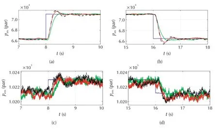
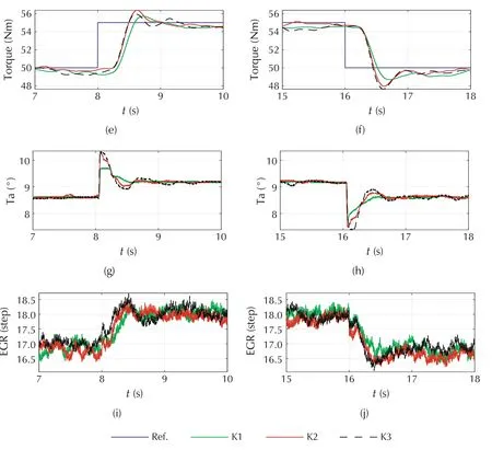
Fig.5 The experimental validation of the proposed controller by using the measured pem.
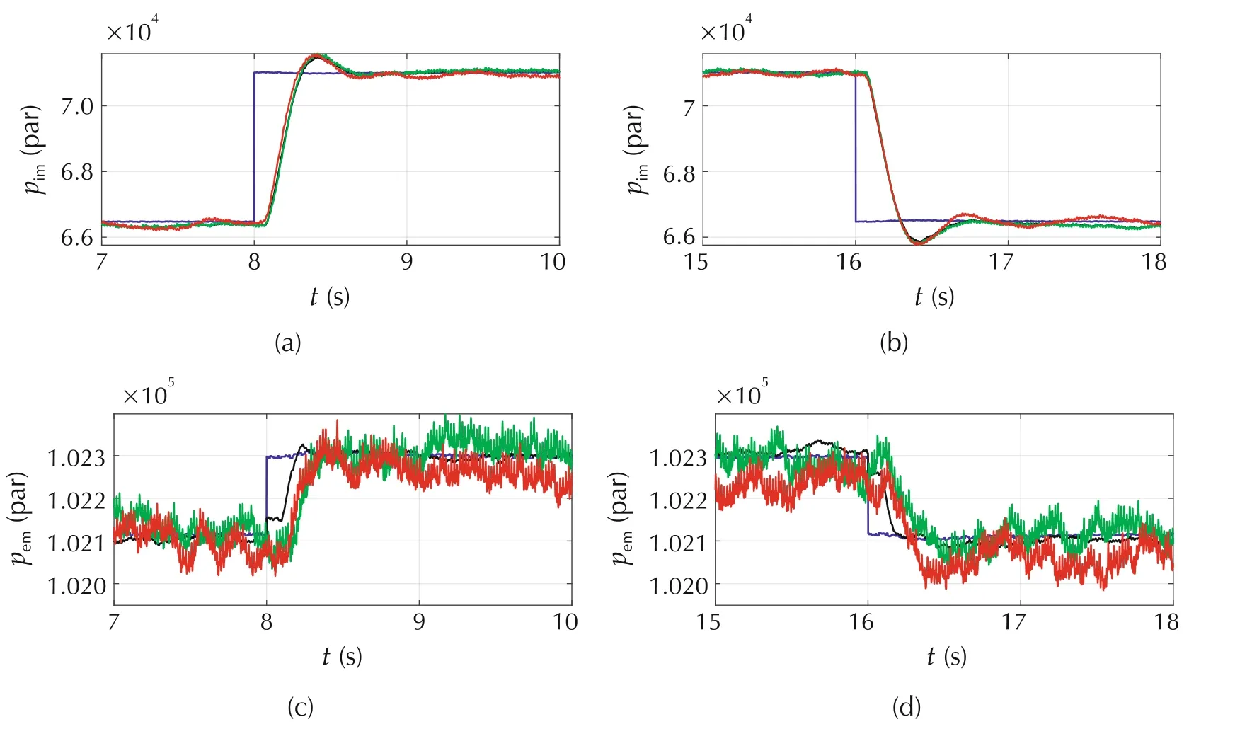
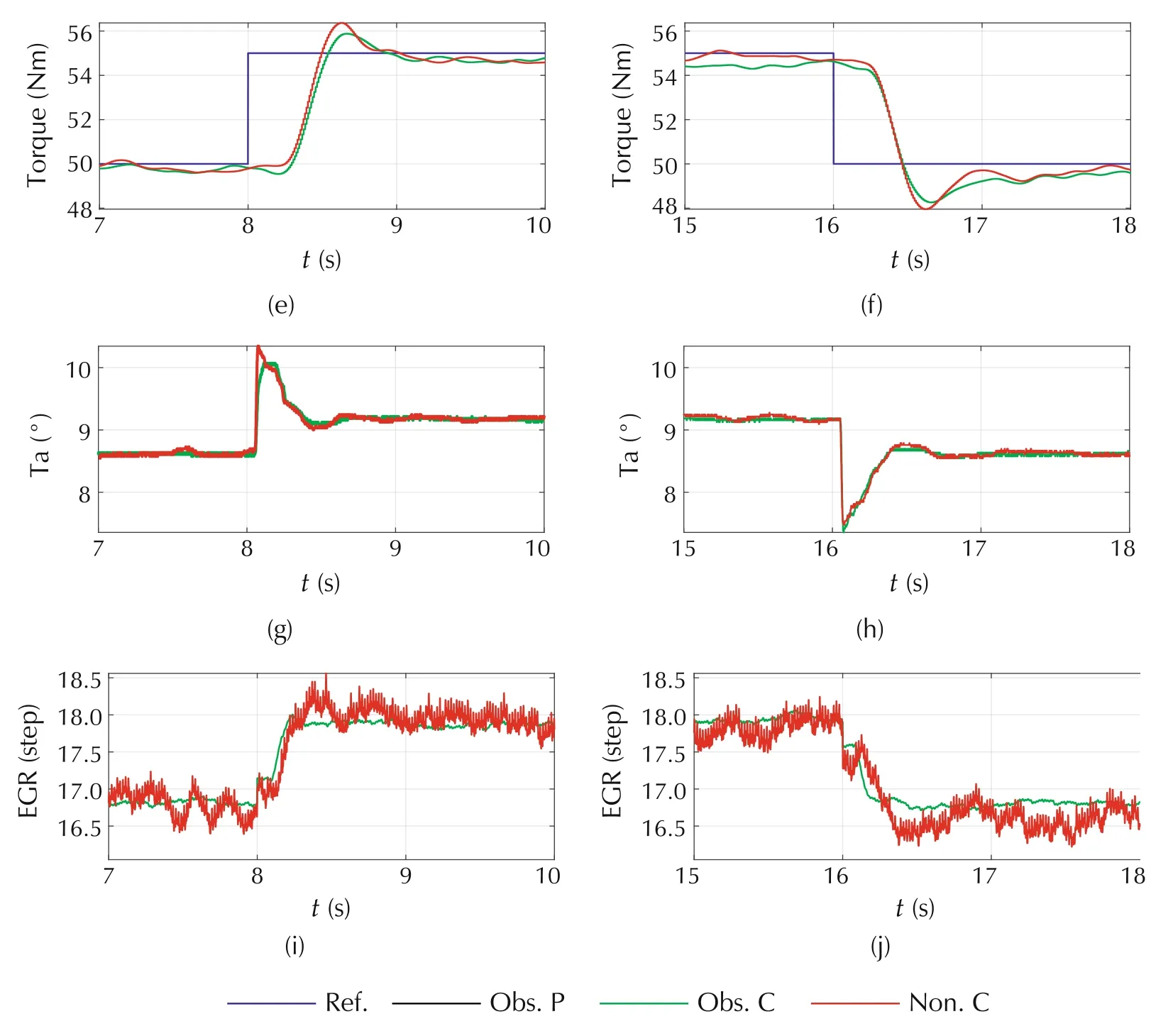
Fig.6 The experimental validation of the proposed nonlinear observer-based control scheme.
4 Conclusions
This paper proposed a nonlinear observer-based stabilization control scheme for gasoline engines with EGR.A second-order nonlinear dynamic model is developed for the air system,based on which the nonlinear feedback controller is designed to regulate the optimal mode of the equilibrium points through the Lyapunov control law with guaranteeing asymptotic stability by selecting the intake manifold pressure and exhaust manifold pressure state as outputs.Further,a nonlinear observerbased feedback controller is designed with guaranteeing the asymptotic stability of the close loop system without depending on the exhaust manifold pressure sensor.Finally,the experimental validations demonstrated that the proposed control scheme can achieve fast transient regulation of the system states to the desired optimal equilibrium points accurately,more importantly,it validated that the proposed control scheme can guarantee the stability of both the observer and the feedback close loop system.
Acknowledgements
The authors would like to acknowledge Toyota Motor Corporation,Japan,for technical supports.
杂志排行
Control Theory and Technology的其它文章
- Parallel loop recovery with quiescent compensation for high performance feedback control of systems with imperfect actuators
- Invariant observer design of attitude and heading reference system
- On the mechanism and control for the ultra-low frequency oscillation in NY Power Grid with large-scale hydropower
- Guaranteed feasible control allocation using model predictive control
- Diagnosability of a class of discrete event systems based on observations
- Optimal finite-dimensional spectral densities for the identification of continuous-time MIMO systems
