Numerical solutions for point masses sliding over analytical surfaces: Part 1
2019-05-28GlaucoGallottiStefanoTinti
Glauco Gallotti*, Stefano Tinti
Department of Physics and Astronomy, University of Bologna, Bologna 40126, Italy
Keywords:Point-mass sliding Two point-mass systems Analytical surfaces Numerical methods Runge–Kutta method
A B S T R A C T In this study, we introduce a system of differential equations describing the motion of a single point mass or of two interacting point masses on a surface, that is solved by a fourth-order explicit Runge–Kutta (RK4) scheme. The forces acting on the masses are gravity, the reaction force of the surface, friction, and, in case of two masses, their mutual interaction force. This latter is introduced by imposing that the geometrical distance between the coupled masses is constant. The solution is computed under the assumption that the point masses strictly slide on the surface, without leaping or rolling. To avoid complications stemming from numerical errors related to real topographies that are only known over discrete grids, we restrict our attention to simulations on analytical continuous surfaces. This study sets the basis for a generalization to more complex systems of masses, such as chains or matrices of blocks that are often used to model complex processes such as landslides and rockfalls. The results shown in this paper provide a background for a companion paper in which the system of equations is generalized, and different geometries are presented.
1 Introduction
The formal description of masses sliding on surfaces finds application in several science branches, from engineering to geophysics. Among the variety of possible applications, we focus our attention on large-scale phenomena, such as landslides, that are of primary importance, especially for hazard assessment analyses.
In general, landslides occur in a variety of forms. The simplest approach is to model a landslide as a rigid body or as a set of interacting blocks moving down a sloping surface. In most cases this is found to represent the landslide motion reasonably well for a broad range of phenomena [1-8]. Similarly, the block models are also used for predicting of the permanent displacements of natural slopes subject to seismic instability [9, 10]. Typically, the sliding body is portioned into a set of blocks sliding down a surface. The motion of each block is described by the motion of the projection of its center of mass moving on a surface. The dynamics of particles and of rigid bodies has been widely studied and investigated [11, 12]. In this paper, we follow the classical approach to describe the motion of a couple of masses over a two-dimensional (2D) surface. The forces acting on the particles are gravity, the reaction force of the surface, the basal friction and the interaction force. This latter is the core of this study and sets the basis for the extension to a more complex system composed of multiple masses and suitable for the description of landslides phenomena. We describe the particles'motion by means of a system of ordinary differential equations(ODE), solved through a series of assumptions we discuss in detail in Sect. 3.
To improve our understanding of the coupled-mass system,in Sect. 2 we propose simulations of the motion of a single mass sliding down a surface. In both cases, the assumption is made that the masses move remaining strictly adherent to the surface,i.e. that the masses can neither leap nor roll, but only slide down the surface.
As we have previously remarked, in the case of coupled masses, we introduce the interaction force. In this paper, we explore the dynamics of a system where this force is such that no elastic deformation is allowed through the joining line between the two particles. Formally, we can obtain this condition by imposing that the three-dimensional (3D) distance between the two masses is constant. This approach is commonly used in block models to avoid the overlapping between a block and its adjacent one [10]. Nevertheless, in this work, we use this geometrical bound to compute the system dynamics. Basically, the rigidity is not imposed as an added condition, but is a factor influencing the motion.
We consider only simulations on analytical surfaces of the type z = f (x, y), where x and y are the horizontal coordinates and z is the vertical coordinate of a Cartesian reference frame. The motion equations imply first- and second-order derivatives of the surface f. Geometrically speaking, the line joining the masses is at any time a chord of the surface. In this paper we will solve the problem under the additional constraint that the angle between the chord and the plane tangent to the surface is small and we will show examples fulfilling such an assumption. The general case will be treated in detail in the companion paper. We believe that the two papers are needed in order to provide a better understanding of the process that leads to the general formulation. This latter can be ultimately applied to systems formed by a large number of interacting particles able to slide simultaneously. The innovation of this approach lies in the fact that the bounds among each couple of particles can be evaluated and studied anytime during the motion. Thus, in the forthcoming description of landslide processes, the sliding body can be modified ensuing hypotheses on the rock properties. These latter can be accounted in the terms of the interaction forces variations.
Sliding surfaces in real cases are known only on a discrete set of observation points, which implies that the related space derivatives can be computed only by means of discrete differential operators and can be obviously known only with less accuracy.Since our primary aim is to focus on the theoretical formulation of the problem and its adequacy to compute the motion of single as well as interacting masses, we consider only analytical surfaces here and leave the problem of the poor knowledge of the real topographical surfaces and of their derivatives to further studies. Pointedly, in this work we use an explicit fourth-order Runge–Kutta scheme (RK4) implemented through a MATLAB code. The RK methods have been widely studied and investigated [13], especially to solve systems of ordinary differential equations [14, 15].
In what follows we first formulate the problem for a single mass system (Sect. 2), then we extend the formulation to cover the case of two interacting mass constrained to lay at a constant distance from each other (Sect. 3).
2 Motion of a single mass
2.1 Formulation of the problem
In this section we formulate the problem of a single mass (a point mass) sliding on a generic analytical surface described by the equation z = f (x, y), where the function f (x, y) is of class C2.We will first introduce the equations of motion in RK4. Eventually, we will show simulations for some selected surfaces.
Let us assume that the point mass slides under the effect of gravitythat in a Cartesian right-hand unit-vector systemwithdirected upward, can be represented as

Let us further introduce a local set of three orthonormal vectorswhereis normal to the surface and points upward,is the maximum-steepness tangential vector (i.e. it belongs to the vertical plane determined byandand points upward),andis the horizontal vector orthogonal toand. In terms of the function f and its first derivatives fxand fy, the local unit-vector system can be given through the following expressions
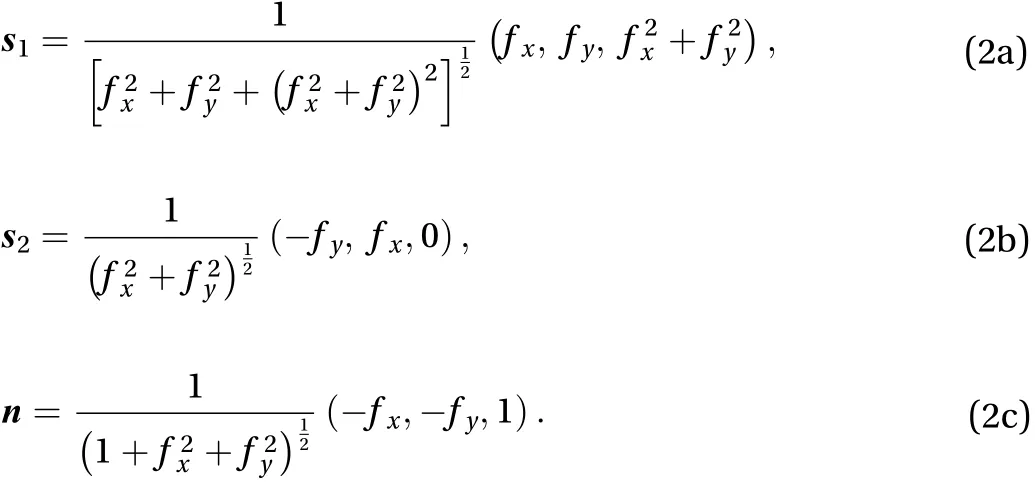
These three unit vectors form the basis of a right-hand Cartesian reference frame and degenerate only in the points of the surface where both derivatives fxand fyare equal to zero.

where the components are given byand.
The reaction force exerted by the surface on the moving point is directed alongand points upward/downward depending on the local concavity/convexity of the surface. Denoting the reaction acceleration by, one can write the following equation for the acceleration of a point mass

Here, it is further assumed that the friction term is proportional to the surface reaction through the friction coefficientand is always directed against the instant unit velocity vector. If one designates the point acceleration component normal to the surface by an, i.e., it is straightforward to deduce the expression for R. In fact, after dot multiplying both members of Eq. (4) by, and noting that, one gets

Considering the decomposition of Eq. (3) the governing equation for the point mass can be given the following form

It is known that the normal acceleration ancan be expressed in terms of the point velocity and of the surface geometrical characteristics. For example, one can writewhere v is the velocity module and r is the local curvature radius. In our approach, it is convenient to express anby means of the expression

that is quadratic in the velocity components and wheredenotes the gradient operator. Taking advantage of Eq. (7), one can observe that in Eq. (6) the point accelerationis expressed in terms of the driving gravity acceleration and of an, that depends on the local velocity. This property makes this formalization suitable to solve the problem through a Runge–Kutta (RK) explicit method.
Since the point is supposedly constrained to move on a surface, the problem can be reduced to a two-degree-of-freedom formulation. Taking into account that from z = f (x, y) it follows that the vertical velocity component vzis given by

and that the vertical acceleration component azhas the form

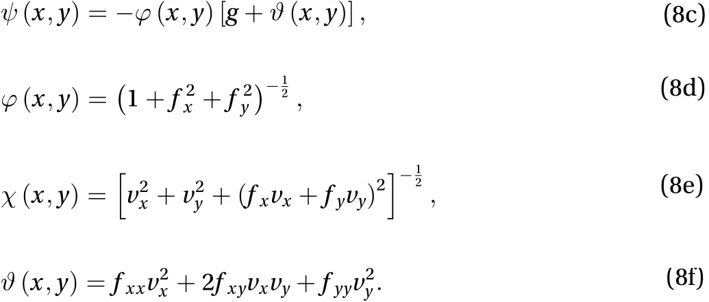
Equation (6) can be solved only for the horizontal components of the point acceleration axand ay. Note that in the above expression the second-order derivatives of the function f have been denoted by fxx, fxy, and fyy. After some manipulations, the governing set of equations becomes

where
2.2 Runge–Kutta method
To solve the above problem, we use an explicit RK4 numerical method. As is known, RK methods were conceived to solve first-order ODE of the type

where t is the independent variable, and w and F may be N component vectors to represent a set of N differential equations.It is easy to see that the second-order ODE problem described by the set of Eq. (8) can be transformed into a first-order ODE,suitable for an RK application, if one poses

and correspondingly poses

RK methods build the solution at the time tn+1by means of an expression of the type

where wnis the solution computed at the time tn, k is the time step,and csare suitable coefficients and. The coefficients ciare such that all times tn+cilie in the interval between tnand tn+1. To compute the intermediate slopesappearing in Eq. (9), intermediate values ofare needed.These are computed by adding increments to wnthat are linear combinations of the previously computed slopeswith j < i.
For the RK4 method adopted in this paper, s = 4 and the coefficients of Eq. (9) are

while the intermediate valuesare computed as

2.3 Analytical solutions
The choice of the RK4 numerical method is based on a series of comparisons against analytical solutions obtained with RK schemes of different order. Basically, we obtained that RK4 is the lowest order RK method providing sufficiently accurate results.We give here only two examples, without and with friction. The solutions are computed through a MATLAB code.
2.3.1 Case 1
The first case we deal with as a test is a frictionless constantvelocity circular horizontal motion that takes place on the inner surface of a spherical cap, given by means of the equation

where R is the sphere radius. It is easy to show that a particle with initial position P0= (0, y0) and initial velocity V0= (v0, 0)describes a circular horizontal trajectory if

One can obtain this condition by considering the point accelerations. If the plane tangent to the sphere at P0has slope,then the horizontal centripetal acceleration associated with the horizontal circular motion of the particle is given by

On the other hand, the acceleration acresults from the sum of the horizontal projections of the effective gravity accelerationand of the centripetal acceleration pointing towards the center of the sphere. Hence, one can write the equation

and deduce that

which is equivalent to Eq. (11).
The motion of the point-mass can be expressed in the form

We computed the solutions through three RK schemes,namely RK2, RK3, and RK4 for a given value of R = 20 m and. With this parameters choice the angular frequency results to be= 0.83 rad/s.
The difference between the values of the numerical radiusand the theoretical radiusis shown in Fig. 1. The RK2 scheme provides the worst result showing a constant drift of the particle over the sphere cap. The RK3 solution shows a similar behavior, but with a smaller drift,whereas RK4 provides the best result with a normalized difference in the order of 10–6.
The difference between the numerical and the exact values of the phaseis shown in Fig. 2. We estimate the phase discrepancybetween the analytical () and numerical () horizontal-position unit vectors by using the cross product formula

Hence, we can write
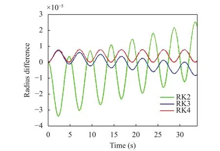
Fig. 1. Differences, normalized to Rsin0, between the analytical and numerical radius values for three RK schemes (Case 1).
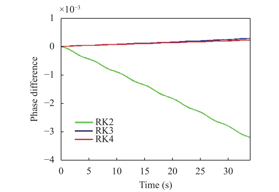
Fig. 2. Shift between the analytical and numerical phases for three RK schemes (Case 1).

The best result is provided by the RK4 method. We observe that the RK2 solution is less accurate with maximum negative differences of 3.0 × 10⁻³. The negative values indicate a delay in the particle motion with respect to the exact solution. The other two schemes perform similarly, with positive differences in the order of 10–4.
For the sake of completeness, we also show the graph of the total energy in Fig. 3, which is constant and is given by

for a unit-mass particle. The relative error, is defined as the ratio of the absolute value of the energy changeto the initial energy E0. By inspection, it is clear that the RK2 method gives the highest error values, in the order of 10–5, while RK4 provides the best results, with relative errors in the range of 10–9.
2.3.2 Case 2
The second test case is a one-dimensional (1D) motion over an inclined plane, under the effect of friction and gravity forces.The equation of the plane is, where the slopeis a positive constant. If we impose that the motion occurs merely in the x-direction, the exact 1D solution for the particle horizontal displacement can be written in the form

where x0is the initial position, v0xis the initial horizontal velocity,is the friction coefficient,is the plane slope, and the sign of the friction term is negative when the motion is downslope and positive when it is upslope.
The grid used to represent the surface is built in the domainand. The initial positions and velocities areand. The angle of the incline is. We compute the numerical and analytical solutions until t = 300 s, with a time step dt = 0.05 s.
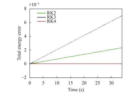
Fig. 3. Total energy errors for the used RK methods (Case 1).
The normalized absolute difference between the values of x(t) computed numerically and analytically is shown in Fig. 4.The normalization factor iswherean dare the final and initial horizontal positions computed analytically. Given the selected parameters, the particle moves backward (and upslope) up to the turning time t = 19.6 s and then it moves forward (and downward) going beyond the initial position. RK2 provides the worst result with discrepancies up to 8 × 10⁻⁵,while RK3 and RK4 produce results similar to each other, with differences more than 4 times smaller.
During its motion, the particle loses energy due to bottom friction. The absolute difference between the instantaneous analytical and numerical energies normalized to the analytical energyis shown in Fig. 5. RK2 shows differences in the order of 10–6, while RK3 and RK4 in the order of 10–7. Also in this latter case the results provided by RK3 and RK4 are essentially the same.
To sum up, all the RK methods provide acceptable solutions,but the RK4 scheme results to be the most accurate numerical method in terms of trajectory computations and system energy estimation and is, therefore, the one we have adopted for the rest of the paper.
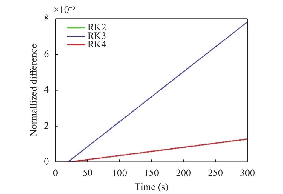
Fig. 4. Absolute differences between analytical and numerical positions, normalized to the total horizontal distance covered by the particle, for RK2, RK3, and RK4. Notice the increasing discrepancy after the turning time due to the inaccurate identification of the time instant where the velocity vanishes (Case 2).
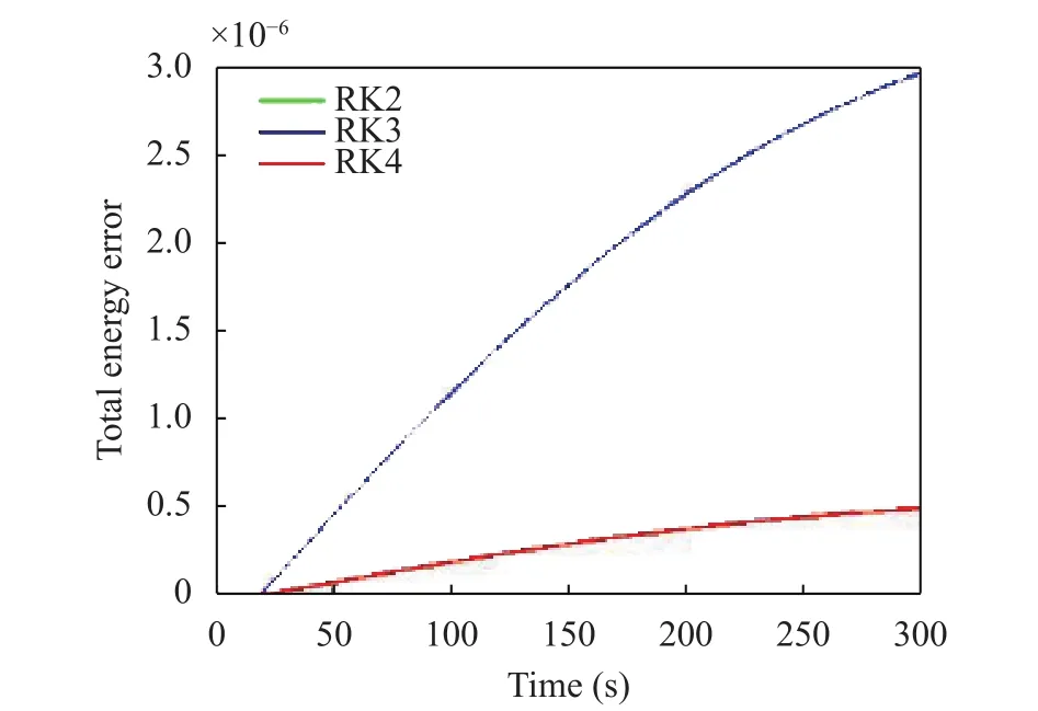
Fig. 5. Absolute differences, normalized to, between the total particle energies, computed analytically and numerically. Notice the increased discrepancies after the turning time (Case 2).
2.4 Examples
In addition to the test cases given in the previous section, we show simulations for which no analytical solutions are available.The space scale is in the order of kilometers, which is typical of geophysical landslide problems.
2.4.1 Example 1
The first bottom surface we take into account is described by the equation

where the values of the coefficients are a = 10–5m–1, b = –5 × 10⁻⁵m–1, and c = 10 m. Due to the surface shape, we will refer to it as a valley, that has a parabolic cross-section and a constant longitudinal mild slope (controlled by the coefficient b). The RK4 solution is computed until t = 103s with a time step dt = 0.1 s.The starting position is (x0= –1600 m, y0= 0) m and the assumed initial velocity is (vx0= 0, vy0= 10) m/s. In the frictionless case we expect that the total system energy is constant. In Fig. 6 we show the particle trajectory (black thick line) on a contour map. The red point represents the starting position, while the range of the particle height is shown on the color bar on the right. As one can see, the mass is pushed downslope in the y-direction since vy0is positive. For this surface, there is no analytical solution, but the expected motion is periodic along the x-direction (valley crosssection) and with uniform acceleration in the y-direction.
In Fig. 7, the relative error of the total system energy is shown. We calculate the error as er=/E0, whereis the absolute difference of the instant energy E(t) and the initial energy E0. The error is very small, of the order of 10–15, which confirms the good accuracy of the adopted RK4 method.
2.4.2 Example 2
The previous case is also treated under the assumption that there exists a friction force (with friction coefficient= 0.002).Figures 8 and 9 show the 2D trajectory and the energy decrease vs. time.
Friction has the effect of damping the oscillations in the xdirection. With the assumed parameters, the particle is expected to come eventually to a stop, but this occurs after we ended the simulation (that is after t = 1000 s).
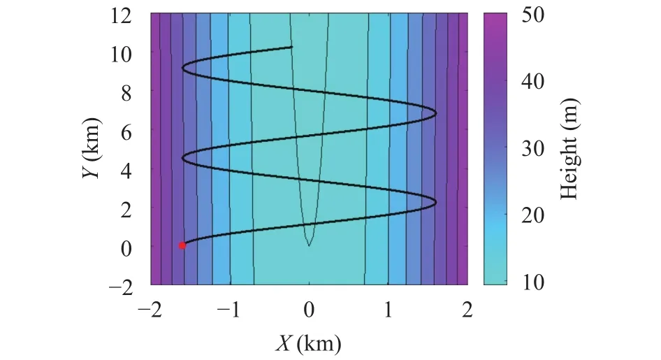
Fig. 6. Particle trajectory (thick black line) and initial position (red solid circle) in the case of a parabolic valley. The color bar on the right shows the vertical surface height z (Example 1).
3 Coupled masses
3.1 Formulation of the problem
In this section, we consider the motion of two coupled particles sliding on a 2D surface. We suppose that the two particles are connected to each other through a peculiar kind of interaction force, that keeps constant the geometrical distance between them.
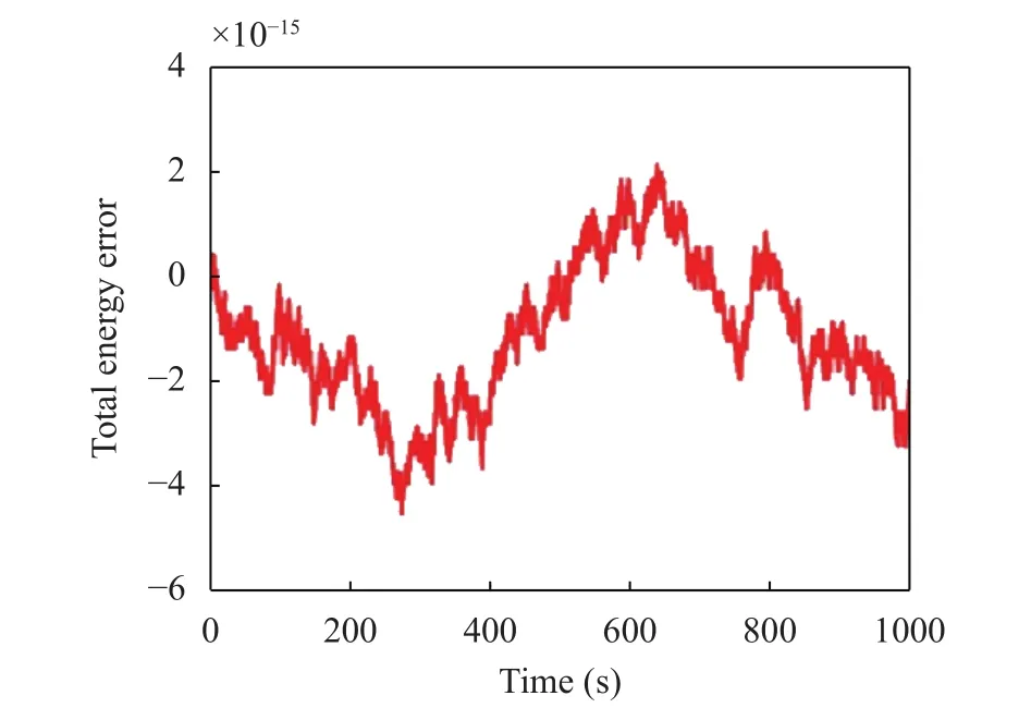
Fig. 7. Total-energy relative error (Example 1).
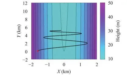
Fig. 8. Particle trajectory (thick black line) and initial position (red circle) in the bottom-friction case. The color bar on the right shows the vertical surface height z (Example 2).
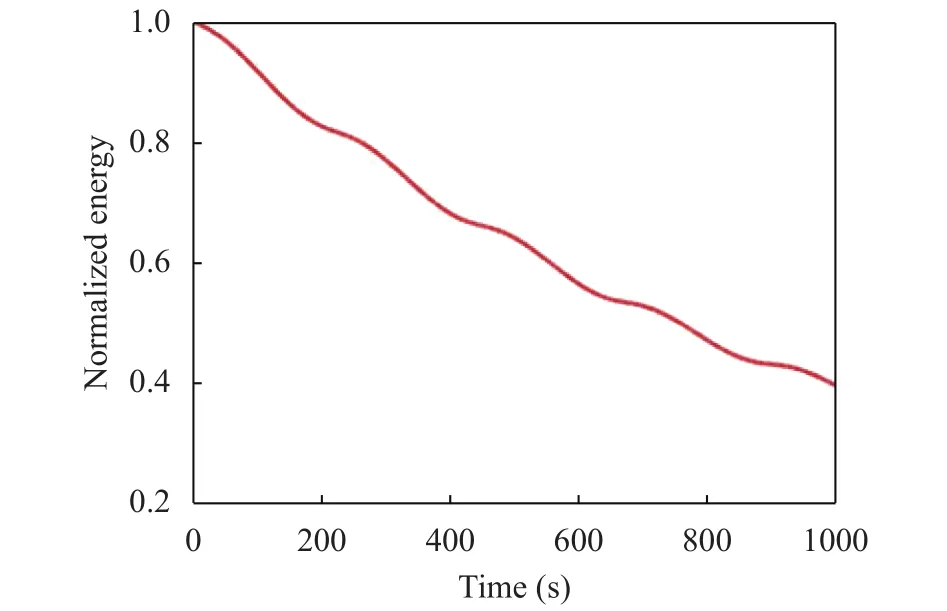
Fig. 9. Total energy normalized to the initial energy E0 vs. time (Example 2).
The masses have the coordinatesandin the space, andandin the horizontal Cartesian plane. Hence, their positions areand.
We can write the constraint on their mutual distance through the dot product as

The equations of motion are

where m1and m2are the particle masses, andandare the external forces acting on the particles, namely gravity pointing downward, the reaction force due to the surface, pointing normal to the surface, and friction, pointing in the direction opposite to the motion. Further,denotes the force exerted on the first particle by the second, andis the one acting on the second particle by the first one. The last terms in Eq. (16)represent the surface reaction to the interaction force. In this paper we give a solution under the assumptions that they are negligible. This happens when the dot product between the interaction force and the local normalsandis close to zero,i.e. whenforms a small angle with the plane that is tangent to the surface in the particle positions. Therefore, the equations of motions are approximated as follows

The complete theory of interacting particles moving on a surface is the subject of the companion paper [16].

After some algebraic manipulations that are fully given in the Appendix, it can be shown thatcan be written as the sum of two parts, one depending on positions and velocities of the particles, and another depending also on their horizontal accelerations. More specifically, the general form of the interaction force can be written as

After moving the linear terms containing the accelerations from the second to the first member of the system Eq. (17), we obtain a system of second-order differential equations. If we introduce the four-component vectors

Equation (17) can be given the compact form

where A is a 4 × 4 functions mass matrix (see Appendix) that depends on the positions and horizontal velocities of the masses, like the vector b.
The system can be transformed into a first-order differential ODE by introducing the auxiliary variable p, that is

Notice that the vector q can be interpreted as a generalized position vector of the two-particles system, since it identifies uniquely the system configuration. Likewise, p is the corresponding velocity vector. Equation (19) of the problem is suitable for RK method solution and we will solve it through an RK4 scheme that in Sect. 2 was shown to be adequate for the single particle dynamics. The general scheme for the discretization process is given by Eq. (9). The difference between the single particle case is that the unknowns are 8 instead of 4.
3.2 Analytical case
The above theory and numerical method can be tested against analytical solutions, that indeed exist only in very special cases. One of these is illustrated here.
3.2.1 Case 3
If we let two equal masses slide down on the constant-slope frictionless inclineunder the effect of gravity and with equal and opposite initial velocities, we expect they spin around the center of mass of the system (CoM), that moves according to a parabolic law

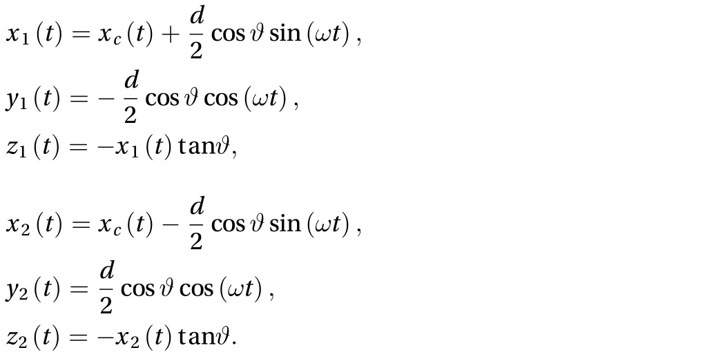

In the numerical example, we set the slope angleto 0.6°.The initial positions are P01= (0, –1000) m and P02= (0, 1000) m.The two masses are equal (m1= m2= 10 kg). The initial velocities are v10= (25, 0) m/s and v20= (–25, 0) m/s.
The computed trajectories are displayed in Fig. 10. The accuracy of the solution is shown by plotting the normalized absolute difference between the analytical values of x(t) and the values obtained through the RK4 method, see Fig. 11. The normalization factor is the radius of the circular motion d/2. Both particles show differences in the range of 10–11, that is totally negligible.
Figure 12 displays the normalized difference between the numerical and the analytical distance that results to be in the order of 10–7. The relative error in computing the interaction force h12is plotted in Fig. 13 and happens to be remarkably small.
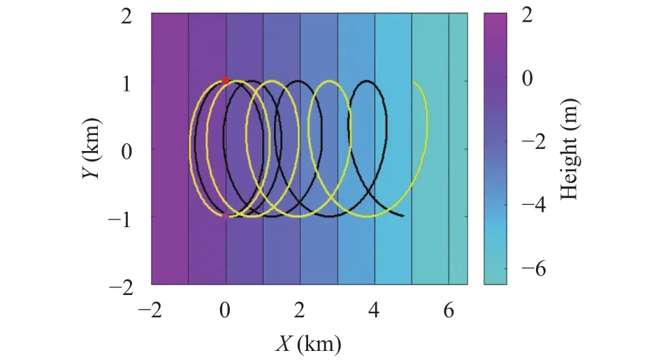
Fig. 10. Mass trajectories. Initial and final (t = 1000 s) positions are shown by circles and triangles. The black and yellow lines denote the first and second particles trajectories, respectively. Positions at the intermediate time t = 500 s are shown by diamonds (Case 3).
3.3 Examples
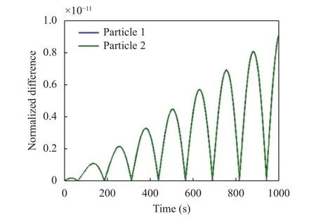
Fig. 11. Absolute differences between the x positions of the numerical (RK4) and of the analytical solutions, normalized to the radius of the circular motion around the system CoM (Case 3).
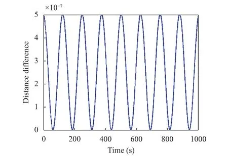
Fig. 12. Absolute difference between the analytical and the RK4-scheme inter-particle distance normalized to the analytical constant distance (Case 3).
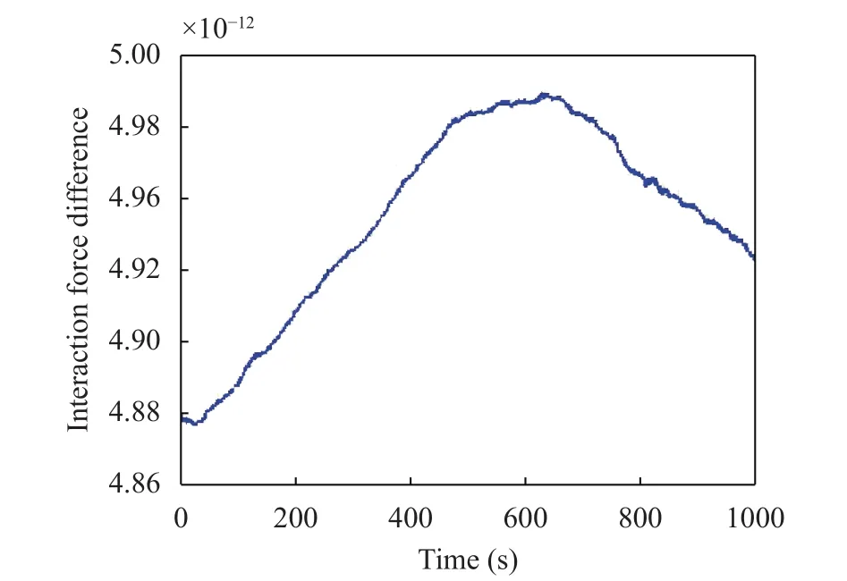
Fig. 13. Absolute difference between the analytical and the numerical interaction force, normalized to |h12| given by (Case 3).
In this section, we treat two more cases of the coupled mass system that do not admit any analytical solutions and where the resulting trajectories are complex, even if the sliding surface is quite smooth.
3.3.1 Example 3
The selected bottom surface is described by the equation

where a = 10–5m–1, b = –5×10⁻⁵m–1, c = 10 m, and can schematically represent a valley with a parabolic cross-section and a constant-slope axis. The bottom surface is supposedly frictionless.
The initial positions are in P01= (2000, –2000) m and P02=(2400, –1500) m. Initial velocities are all set to zero. Particles have masses: m1= 100 kg and m2= 10 kg. We will see that a considerable mass unbalance can lead to very irregular trajectories for the lighter mass, that is strongly influenced by the other as the effect of the interaction force.
The trajectories of the masses are plotted in Fig. 14. It can be noticed that the trajectory of the heavier particle shows a smoother path, while the trajectory of the other mass exhibits a series of highly complex transversal oscillations, with forward as well as backward motion, mainly due to the action of the interaction force.
There are invariants in the motion of the particles. The first is the distance between the particles, and the second is the total energy. Indeed, since the interaction force acts to keep the particle at a constant distance, it is responsible of the instant rotation of the masses around the CoM of the system and happens to be normal to their instant velocities. It follows that it does not perform any work on the system, and hence we expect that the total system energy, given by the sum of the total energies of the two masses, be conserved. As is evident in Fig. 15, the total system energy is constant with relative errors in the order of 10–6.And Fig. 16 shows that the distance is conserved with a relative error in the order of 10–12.
The interaction force changes with time. It is interesting to examine its behavior, that is displayed in Fig. 17, where it is normalized over the gravity force. One can see that h12completes more than 7 periods in about 1000 s. One could be tempted to relate the period of the interaction force to transversal oscillations of the masses, but the trajectory graph(Fig. 14) shows that the motion along the flanks of the valley possesses a longer period and describes about 4.5 oscillations in the same 1000 s time interval. So what is remarkable is that in this example the particle motion is characterized by a double frequency: one due to the sliding down the cross-section and the other due to the interaction force. This changes from positive to negative regularly, which means that it passes from repulsive to attractive.
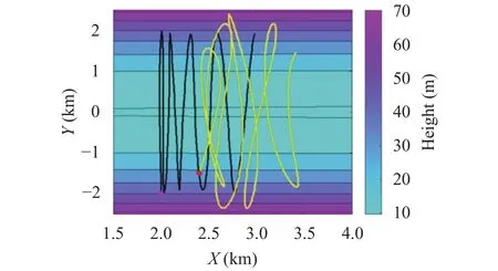
Fig. 14. Mass trajectories. Initial and final (t = 2000 s) positions are shown by circles and triangles. The black and yellow lines denote the first and second particles trajectories, respectively. Positions at the intermediate time t = 1000 s are shown by diamonds (Example 3).
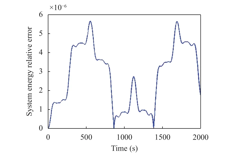
Fig. 15. Total system energy relative error in the absence of dissipative bottom friction (Example 3).
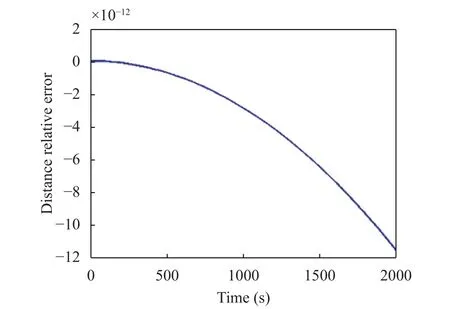
Fig. 16. Relative error of the inter-particle distance (Example 3).
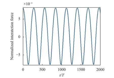
Fig. 17. Interaction force vs. time, normalized over m1m2g/(m1 +m2) (Example 3).
3.3.2 Example 4
The case of Example 3 is also treated under the assumption that there exists a friction force (= 0.002), all the rest remaining equal. Figure 18 portrays the trajectories for this case. Paths are similar to the ones of Example 3 (with no friction), but do not intersect and cover different regions. The lighter mass moves more irregularly, exhibiting also backward loops. There is an expected loss of energy due to the dissipation taking place at the surface, as is shown in Fig. 19, where the system total energy,normalized to the initial value E0, is plotted. The RK4 solution keeps the inter-particle distance constant also in case of friction,with the relative error being in the order of 10–11.
4 Conclusions
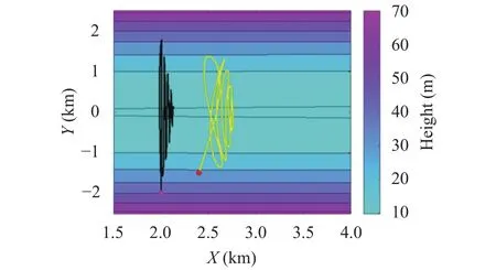
Fig. 18. Trajectory of two unequal coupled masses along a parabolic valley. Initial and final (t = 2000 s) positions are shown by circles and triangles. The black and yellow lines denote the first and second particles trajectories, respectively. Positions at the intermediate time t = 1000 s are shown by diamonds (Example 4).
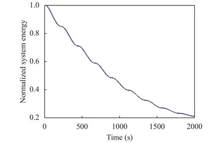
Fig. 19. Decay of the system total energy (normalised to the initial energy E0) due to the bottom friction (Example 4).
In this paper, we have treated the classical problem of a particle sliding on a surface, as well as the problem of a system of two particles coupled by means of an interaction force keeping constant their distance. In the former case the forces acting on the particle are gravity, the reaction force of the surface and the surface friction. In the latter case, also the interaction force is active. The formulation of the first problem leads to a system of two second-order differential equations for the particle horizontal coordinates x(t) and y(t), that can be transformed into a four-equation RK scheme. The formulation of the second problem, which is original and fully given in the Appendix, leads to a system of four equations and to a corresponding eight-equation RK system.
In the paper, we have shown that the RK numerical method is adequate to solve the problem, but in order to obtain highquality results at least a fourth-order scheme, that is an RK4, is required. This was proven by comparing numerical results obtained also with lower-order RK methods against analytical solutions with and without friction. Results for this comparison have been displayed in the paper only for the single particle cases, but tests have been run also for the coupled particles dynamics with identical conclusions.
The analytical cases we propose as comparison are simple,regarding constant slope planes or spherical cups, but some of them are not at all trivial, such as the cases of the mass travelling along a circular horizontal trajectory with constant speed (see Sect. 2.3) on the spherical cup, and the case of two particles sliding on a constant incline and rotating around each other (see Sect. 3.2). These analytical solutions can be seen as powerful benchmarks to measure the performance of any numerical method to solve particles sliding problems.
As regards the only analytical case for the two-particle system mentioned above, it is worth pointing out that it provides also the expression of the interaction force, which results to have a constant magnitude that is proportional to the mass M12, to the square of the rotational velocity, and inversely proportional to the particles distance (see Eq. (20)). This expression is useful since it provides an order of magnitude for |h12| that is valid even for more complicated surfaces for which no analytical solutions exist, but that can be, even roughly, approximated by a constant incline.
The pure numerical examples given in the paper served the purpose to show that RK4 implemented code was accurate enough to conserve the constants of the motion (that is the energy, for frictionless motion, and the particle distance for coupled particles cases). We stress that the code can be used to treat any kind of initial conditions, and, moreover, in view of the very good results we obtained, it is expected to provide very accurate solutions even for complicated particles motions. Indeed,when the masses of the particles are very unbalanced, the lighter particle is expected to have a chaotic path around the more massive one along the slope, and a hint for this is the last case we treated in Sect. 3.3.
We have often used geological terms to describe surfaces,such as valley and depression. The reason for this is that this study is part of a research aiming at developing a new numerical code for landslides sliding down realistic mountain slopes, with the landslide represented as set of points (or blocks) interacting with each other. So, the final aim is to develop a theory and to implement a corresponding code handling N points with N being considerably larger than 2, with mutual links that might also be broken during the motion. This will allow us to simulate rockslides where blocks may fracture and break into fragment while sliding. If the focus is on geological slides, the role of friction and fragmentation is crucial and what matters most is the downslope fall phase, since no climbing of the landslide uphill does usually occur and no up-and-down oscillations across a valley are observed. We believe, however, that developing a complete code providing results even for frictionless constant-energy motion is a way to create a tool allowing for a better understanding of the basic physics and ultimately for more reliable simulations.
5 Acknowledgements
The research conducted in this paper was mostly financed by the FP7 Project ASTARTE “Assessment, Strategy and Risk Reduction for 740 Tsunamis in Europe” (FP7-ENV2013 6.4-3, Grant 603839) and by the Italian National Project RITMARE that,among others, treat landslide models with tsunamigenic potential.
Appendix
Subtracting Eq. (17b) from Eq. (17a), we get

After dot multiplying both members of Eq. (A.1) by,we obtain

On the other hand, if we derive Eq. (15) twice with respect to the time, we obtain

which can be rewritten as

After replacing Eq. (A.1) in Eq. (A.2), we can write

If we assume that the interaction forcelies on the direction joining the two particles, we can write the following expression

Substituting Eq. (A.4) into Eq. (A.3), we obtain the scalar h12that is positive when the force points towards the first particle,and negative if the force points towards the second particle

Considering that vertical velocities and accelerations can be expressed by means of their horizontal counterparts, i.e.

and making use of Eq. (A.4), the interaction force takes the form


In Eq. (A.7) and hereafter, by f1xand f1ywe denote the first derivative of the surface function f with respect to the space coordinates x and y, evaluated in the position of particle 1. Likewise, f2xand f2yare the derivatives taken in the position of the second particle. And similar notation is used for the second derivatives. It is worth observing that=, that is it does not change if one exchanges the position of the two particles. After introducing the following definitions
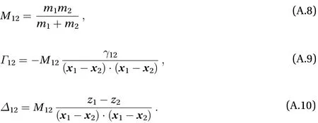
Equation (A.4) can be given the compact form

It is important to stress that, strictly speaking, due to the way it was derived, the expression (A.11) does not ensure that the particle distance is constant during the motion, but rather that its second derivative with respect to time is zero (see Eq. (A.2)).This means that it is allowed to change with a constant rate, and if the initial conditions are suitable, it remains constant (for instance, if the particles initial velocities are assumed to be zero).Observe further that from the above definitions (A.8)–(A.10), it follows that M12= M21,, but. Using Eq.(A.11) for the interaction force, the equations of motion for the two particles along the horizontal axes x and y can be written as


This is a system of second-order differential equations in the four unknown functions x1, y1, x2, and y2that can be formally written as

where

Notice that the four-component vector bT, which has the dimension of a force, contains only masses, positions and horizontal velocities of the particles, and accounts for the forces F1and F2. The mass matrix A has the form

and depends on particles masses and positions.
杂志排行
Theoretical & Applied Mechanics Letters的其它文章
- Particle selectivity of filtering by C. elegans
- The extractable hydrokinetic power from an oscillating membrane-based harvester
- Impact of spray droplets on momentum and heat transport in a turbulent marine atmospheric boundary layer
- A new numerical framework for large-eddy simulation of waves generated by objects piercing water surface
- Numerical solutions for point masses sliding over analytical surfaces: Part 2
- Marangoni liquid film scattering over an extending cylinder
