The extractable hydrokinetic power from an oscillating membrane-based harvester
2019-05-28FranciscoAriasSalvadorDeLasHeras
Francisco J. Arias*, Salvador De Las Heras
Department of Fluid Mechanics, University of Catalonia, ESEIAAT C/ Colom 11, 08222 Barcelona, Spain
Keywords:Energy harvesting Residual waters Waste waters
A B S T R A C T The extractable hydrokinetic power from an oscillating membrane in standing motion and induced by a water flow and its possible significance with regard energy harvesting is discussed.The main attractiveness of such an energy harvester lies in the possibility of an inexpensive technology able to be used in those water flows which either because limitation of space (narrow channels) or a limited differential pressure drop with the surrounding but yet with a non negligible velocity are not well suited to be turbined. Utilizing a simplified geometrical model, an estimate of the extractable output density power per area of membrane was derived. Preliminary experiments were performed using a rectangular thin rubber membrane and for a typical domestic water intake as source. The experimental data quantitatively agree very well with the theoretical prediction where it was found that for water flows around 2 m/s the output power density from the membrane may be around 30 mW/cm2 of membrane. Additional research and development is required in order to arrive at a reliable practical and commercial design.
Energy harvesting or energy scavenging is the process by which wasted energy can be captured and stored from different types of waste sources and technologies and used for small,wireless autonomous devices with typical inputs from 1 W up to perhaps a few mW. Different sources can be used such as piezoelectric energy [1, 2], wind energy [3, 4], thermal energy [5], salinity gradients [6], triboelectricity [7], vibrational energy [8], and hydrokinetic energy [9] including wave energy conversion [10],just to name a few. In regards to hydrokinetic power, which is electricity generated from water in motion, the current harvesting technology is almost entirely based on the use of water turbines, which transform the water‘s energy into mechanical energy, similar to the way wind turbines transform wind energy,and although they can vary in size and design, they are generally classified into three main types as vertical-axis hydrokinetic turbines [11], horizontal-axis hydrokinetic turbines [12], and oscillating-foil hydrokinetic turbines [13]. For readers interested in an up-to date review on hydrokinetic energy conversion, see Ref.[9]. However, turbines require a minimum pressure drop with the surrounding environment as well as a minimum cross-sectional area (generally limited by the width of the blades), and then, they are therefore often not a feasible solution for application in residual waters which frequently move through narrow channels and generally move at low total pressure (dynamic plus static); in addition, they frequently transport solid material that may jeopardize the performance of the turbine. The objective of this work was to analyse a possible novel hydrokinetic energy harvester based on the use of compliant surfaces or membranes that are more suitable for residual waters, i.e., water flows with a low total pressure relative to the surrounding environment.
The object of this work was a first estimate of the extractable power output density from a kind of hydrokinetic energy harvester based in the use of an oscillating membrane driven by a water flow. This kind of hydrokinetic energy harvester may be an interesting inexpensive alternative for those water flows not suitable to be turbined either because a limited differential pressure drop with the surrounding or a limitation in space but yet with a non negligible velocity. Such waters encompass not only domestic or industrial waste waters before being discharged into the sewer but also typical flows found in river waterways of small depth or in post-turbined waters.
Consider a water stream which is deliberately separated into two regions by using a cavity with a single, rectangular membrane of width b and negligible thickness as pictorially sketched in Fig. 1. The membrane is allowed to move freely up-and-down along its longitudinal sides by allowing a certain gap, but fixing the membrane at the ends. The water flow is only allowed to exit by one of the regions, say, the bottom region in Fig. 1.
It is easy to see that, immediately the cavity is filled with water, the upper region will be almost at rest and the water will flow only through the bottom region. As a result, the static pressure in both regions is equalized but keeping a relative difference in dynamic pressure. Because this relative dynamic pressure between the sides of the membrane Taylor-Helmholtz hydrodynamic disturbances appear and translate into the oscillatory motion of the membrane. With this although rather simplified picture of the proposed hydrokinetic energy harvester we can proceed with some preliminary theoretical treatment as follows.
To begin with, because the two ends of the membrane are firmly secured ("clamped") by using some support, therefore the membrane will not move at the ends and as a result of this boundary conditions, the wave will move in a standing fashion.In view of the several uncertainties in the specific conditions of the system, and for preliminary estimations as well, the simplest expression for a standing wave, seems preferable

First, the normal pressure gradientto the surface at a given chosen point is

where dp is a a differential pressure, dr a differential radial pressure which is in the same direction than the local radius of curvature of the membrane i.e., normal to the surface;and U are the density and stream velocity of the fluid at that point,respectively; R is the local radius of curvature of the membrane.The actual shape of the membrane surface and the physical model used in the next analysis is shown in Fig. 2.
For very small disturbancesas is our case, the local centrifugal force given by Eq. (2) may be calculated considering the following theoretical treatment.
On one hand the radius of curvature is calculated as [14]

which considering Eq.(1) yields

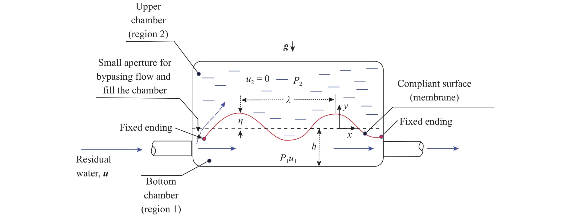
Fig. 1. Physical sketch of the proposed membrane-based energy harvester.
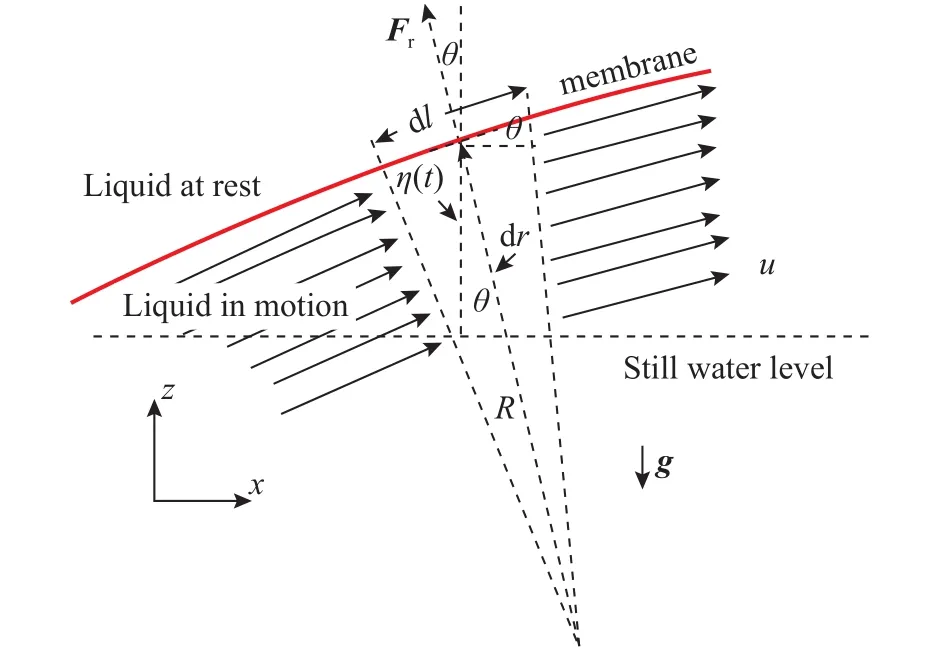
Fig. 2. Physical model for the oscillating membrane.
On the other hand it is seen from Fig. 2 that,


and then taking into account Eq.(1)

for our case of study with very small disturbances and comparatively large wavelength, i.e,, the following simplification is valid for any time t and position x

and then

Therefore, Eq.(5) becomes

Taking into account Eq.(10), then Eqs. (2) and (4) obtains

and the "centrifugal" inertial force acting on the region of infinitesimal length dl and width of the wave b as

and its vertical component


and the power is calculated as

and the density power by unit area of membrane dlb

The time-averaged power over one cycle is obtained as

where it was considered that. The maximum density power when the harvester is obtained when the relationsfor n = 0, 1, 2, ... is satisfied

It is convenient to express Eq. (18) as function of the wavelengthas

On the other hand, if one considers the natural frequency of oscillation for a stretched membrane given by [15]


In order to obtain some idea of the shape of the curves predicted by Eq. (21), we assume some typical values of the parameters: A somehow typical rubber membrane withkg/m2and surface tension= 1.36 N/m, i.e, withm/s; a water density= 103kg/m3. The resulting curves are shown in Fig. 3. It is seen that the extractable power density for velocities up to 2 m/s, as it can be found in domestics intakes,and probable values of, is between 1 mW/cm2up to 0.1 W/cm2.
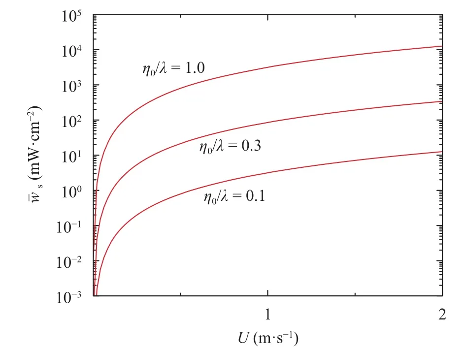
Fig. 3. Plot of the density power as function of the water flow.
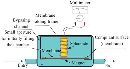
Fig. 4. Sketch of the experimental setup.
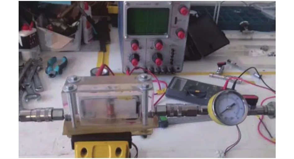
Fig. 5. Real experimental setup.
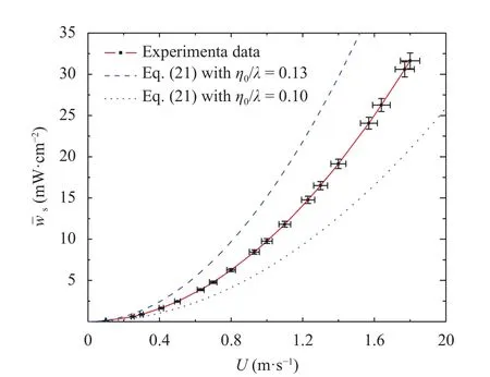
Fig. 6. Plot of the surface density power output as a function of the water velocity for the studied experimental cavity.
Finally in order to gain a certain confidence in the theoretical predictions from the model, an experiment was performed using a rectangular narrow cavity 7.5 cm long, 5.5 cm high and 1.3 cm in width and with two perforations of 0.95 cm in diameter(for the entry and exit of water) and centered in the sides of the cavity at 0.89 cm from the bottom. A commercial thin rubber membrane with a surface tension of 5.5 N/m and a mass per unit area 3.2 kg/m2and 6 cm long 1.2 cm in width was located at 1.4 cm from the bottom separating the cavity into two regions. The membrane was secured at the ends by an aluminium frame, and with a gap in the longitudinal sides of 0.1 cm allowing the membrane move freely up and down.
The cavity was built with methacrylate for visualization, and the frame with aluminium to avoid damping effects with the linea inductor electromagnetic system used for conversion of the motion into electrical output. This linear inductance generator simply consisted of a permanent magnet attached at the surface of the membrane and moving through a coil located vertically,see Fig. 4. The single coil was a conducting copper wire loop 2.5 cm long, and with an external diameter 1.0 cm, and internal diameter 2.35 mm, electrical resistance R = 1000and situated in front of the permanent magnet attached at the membrane and 0.4 cm from the membrane when it was at rest. The coil was fixed at the top using the aluminium frame (the same used to fix the membrane). The permanent magnet was a strong neodymium magnet of 20 grams in weight, 1.2 cm in diameter and with a magnetic field at its surface of 0.2 T. Figures 4 and 5 show the sketch and real configuration of the experimental apparatus, respectively.
For the measurements, a flow of fresh water of density= 103kg/m3and kinematic viscosity= 0.01 cm2/s from a domestic water intake with a 3.5 bar exit pressure and 290 K of temperature was used.
The resulting curve is shown in Fig. 6 and compared with the theoretical best fit from Eq. (21). It is seen that the attainable density power is around 30 mW/cm2for a velocity around 1.8 m/s and with a best fit for the theoretical prediction within0.13 towhichis a very god predictionifit is considered thatthe amplitudes and wavelengths observed were around 0.4 cm and 2.5 cm, respectively. Nevertheless it must be considered the strong power-law dependence with the parameterpredicted byEq.(21)
The extractable hydrokinetic power from an oscillating membrane in standing motion and induced by a water flow and its possible significance with regard energy harvesting is discussed. Utilizing a simplified geometrical model, an estimate of the extractable output density power per area of membrane was derived. It was found that the extractable output power density from the membrane is strongly dependent on the amplitudewavelength ratio with a power-lawof the wave. For water flows around 2 m/s the extractable output power density from a typical thin rubber membrane with water flow around 1.7 m/s the power density could be around 30 mW/cm2of membrane. An experimental was developed and the experimental data obtained agree qualitatively and quantitatively with the theoretical prediction.
NOMENCLATURE
b = width of the compliant surface
dr = deferential in the direction of radius of curvature
F = force
dl = infinitesimal length of surface membrane
p = pressure
R = radius of curvature
Re= electric resistance
t = time
T = wave period of small disturbance
U = flow velocity
v = velocity
x = length co-ordinate
w = power
z = vertical co-ordinate
Greek symbols
subscripts symbols
o = initial or reference value
r = radial normal to surface
s = surface
z = vertical-coordinate
ACKNOWLEDGEMENTS
This research was supported by the Spanish Ministry of Economy and Competitiveness under fellowship grant (Ramon Cajal: RYC-2013-13459).
杂志排行
Theoretical & Applied Mechanics Letters的其它文章
- Particle selectivity of filtering by C. elegans
- Impact of spray droplets on momentum and heat transport in a turbulent marine atmospheric boundary layer
- A new numerical framework for large-eddy simulation of waves generated by objects piercing water surface
- Numerical solutions for point masses sliding over analytical surfaces: Part 1
- Numerical solutions for point masses sliding over analytical surfaces: Part 2
- Marangoni liquid film scattering over an extending cylinder
