A new numerical framework for large-eddy simulation of waves generated by objects piercing water surface
2019-05-28ZixuanYangZuoCuiShizhaoWang
Zixuan Yang, Zuo Cui, Shizhao Wang,*
a The State Key Laboratory of Nonlinear Mechanics, Institute of Mechanics, Chinese Academy of Sciences, Beijing 100190, China
b School of Aerospace Engineering, Guizhou Institute of Technology, Guiyang 550003, China
c School of Engineering Sciences, University of Chinese Academy of Sciences, Beijing 100049, China
Keywords:Large-eddy simulation Wave breaking Wave–structure interactions
A B S T R A C T A novel numerical framework is developed for large-eddy simulation (LES) of interactions among air, water, and solid bodies. The motions of air and water are solved on a fixed block-structured mesh, with the air–water interface captured using the volume-of-fluid method. A new sub-grid scale stress model based on the vortex identifier is used to improve the robustness and efficiency of the simulation flows with air–water interface. The new framework is tested in the context of bow waves and Kelvin waves generated by a water-surface vehicle. Wave breaking at the bow of the vehicle is captured in LES. The LES results of wave geometry approaches the measurements progressively as the grid resolution is refined. The simulation results indicate that LES is a useful tool for studying wave dynamics of water-surface vehicles.
When a solid body is piercing water surface at a high speed,violent breaking waves can be generated, which impose additional resistance on the body. As a result, the investigation of wave–structure interaction is fundamentally important for the design and maneuvering of water-surface vehicles. While experimental studies of wave–structure interaction are usually timeconsuming and expensive, the large-eddy simulation (LES) is believed to be a useful tool for the early-stage design of watersurface vehicles [1, 2].
In the LES study of waves generated by a water-surface vehicle, one of the main challenges is the numerical method for capturing waves. There are two categories of numerical approaches for simulating two-fluid flows, namely the front-tracking and front-capturing methods. The former method solves the air and water separately to provide a sharp interface between air and water [3, 4]. However, when applied in the physical problems with violent breaking waves, the computational cost of the front-tracking method can be large due to the complex geometry of the air–water interface. Solving the motions of air and water on a fixed grid, the front-capturing methods are less demanding in computer power and more robust for complex waves. In these methods, the density and viscosity change with the fluid phase [5]. To avoid any numerical instabilities, the density and viscosity need to change gradually in several grid points across the interface. As a result, the interface is essentially diffused, and the surface tension cannot be calculated accurately. However, in the simulation of waves around a watersurface vehicle, the surface tension is less important, because the scale is usually large. As such, the front-capturing methods are chosen in the preset numerical framework for its capability in capturing breaking waves with arbitrary geometries.
Besides the air–water interface, the fluid–structure interface also needs to be captured accurately in the numerical studies of waves generated by water-surface vehicles. The immersed boundary (IB) method is effective in capturing complex geometries of solid bodies on an Eulerian grid. In the IB method, the boundary condition at the body surface is satisfied by imposing a forcing at grid points adjacent to the body surface. The details of the IB method are introduced comprehensively in the review paper [6].
The goal of the present project is to develop a numerical framework called computational air–sea tank (CAS-Tank) for LES of waves generated by water-surface vehicles. As a start, the following features of the numerical framework are expected:
1. high performance in parallel computing;
2. correct representation of the geometry of the water-surface vehicle;
3. accurate prediction of wave geometry.
These three criteria are used to examine the performance of the CAS-Tank in the context of two-fluid flow past a standard ship model DTMB-5415 [7].
The fluid flow is governed by the following continuity and momentum equations for incompressible flows:
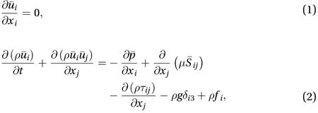
The density and viscosity vary with the fluid phase, calculated as


This equation is solved using the conservative volume-offraction method [8].

The first term on the right-hand side of Eq. (6) is merged into the pressure. The SGS viscosityis calculated using a new vortexidentifier model (VIM) as [9]

Equation (2) is discretized on a fixed block-structured mesh[14]. In the region away from the water surface, a second-order central difference scheme is used to calculate the convection term in the momentum equation, while near the water surface, a second-order essential non-oscillatory scheme is used to improve the numerical robustness [15]. The viscous term is calculated using the second-order central difference scheme in the entire domain. The projection method is used to satisfy the divergence-free condition (1). The second-order Runge-Kutta method is applied for time advancement.
The performance of the CAS-Tank is tested in the context of flow past a fixed ship. A uniform flow at a constant streamwise velocityis prescribed at the inlet, and a convective condition is used at the outlet. Free-slip conditions are applied at the top,bottom, and two side boundaries of the computational domain.The no-slip boundary condition at the ship surface is imposed by using the IB method.
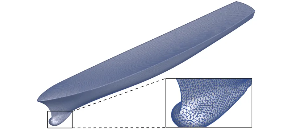
Fig. 1. Triangular mesh on ship surface.
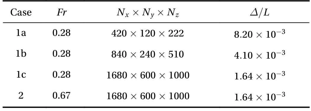
Table 1 Key parameters of test cases.
Table 1 summarizes the key parameters of the test cases. As shown, the Froude numberis set to 0.28 in cases 1a–1c to match the laboratory experiment [16], such that the LES results of wave geometry can be compared with the measurements. Here,is the inflow velocity andis the length of the ship. In case 2, a larger value ofis considered to examine the effect of Froude number on the wave geometry. The number of grid points varies from 11,188,800 to 1,008,000,000 in cases 1a–1c to examine the effect of grid resolution on the results. Near the ship, the grid is refined, and the resolutionis listed in the table. Note that the grid resolution in the three directions is the same near the ship, i.e.. The grid is gradually stretched to the ends of the computational domain.The time step is determined dynamically based on the Courant–Friedrichs–Lewy criterion as, where,, andrepresent the velocity components in,, anddirections, respectively.The minimum operator is performed over the three components and all grid points. The computational domain size is set toin all cases. The distance between the ship bow and the inlet of the computational domain is. The Reynolds numberis fixed toin all cases, smaller than that in the laboratory experiment [16]. This leads to a discrepancy in the resistance between LES and experiments. However, at the initial stage of developing a comprehensive numerical framework, we focus on the accurate prediction of wave geometry. According to previous studies of wave breaking, the Reynolds number is not a key parameter that influences the wave geometry [17]. As a result, we reduce the Reynolds number to examine the capability of the numerical algorithm in capturing the wave geometry.
The scalability of parallel computing was tested using case 1b. We ran the same case using different number of CPU cores for 100 time steps, and the time cost for the simulation was recorded. To avoid any unexpected influence of computer condition, each run was conducted for 20 times to obtain an averaged time cost. Figure 2 compares the time cost for different number of CPU cores, normalized by the time for 126 CPU cores. The dashed line in the figure shows the linear speed-up ratio, an ideal condition for an efficient parallel computing. It can be observed from the figure that asincreases from 126 to 1004, the simulation is accelerated almost at a linear ratio, indicating a good performance of CAS-Tank in parallel computing.
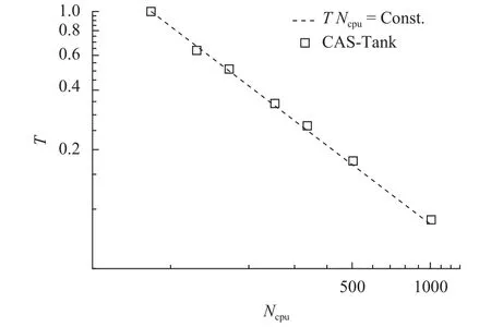
Fig. 2. Time cost for running case 1b using different number of CPU cores.
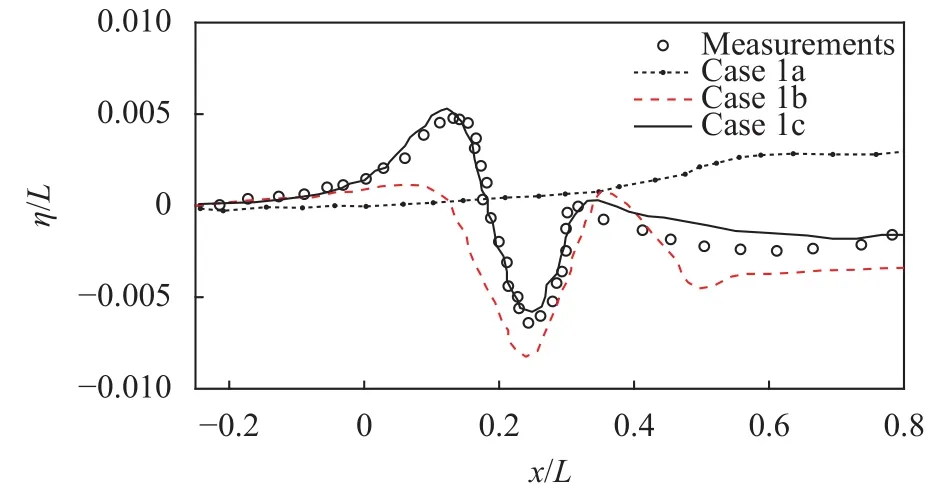
Fig. 3. Elevation of water surface at z = 0.082L obtained from CASTank and laboratoryexperiments [16].
Figure 3 compares the wave geometry atobtained from CAS-Tank and laboratory experiments [16]. Here,represents the central plane of the ship. It is shown that as the grid resolution is refined, the wave geometry approaches the measurements progressively. Specifically, the wave geometry of case 1a is incorrect due to the use of coarse grid. With a finer resolution, case 1b makes a better perdition on the wave length. As shown in the figure, the locations of the wave crest and wave trough obtained from case 1b is consistent with the measurements, but the wave amplitude is not satisfactory. As the grid is further refined in case 1c, both wavelength and wave amplitude obtained from CAS-Tank become consistent with the measurements. The results shown in Fig. 3 indicate that the grid resolution is critically important for making a good prediction of the wave geometry.
Figure 4 compares the Kelvin ship waves at two Froude numbers. It is shown that the wave amplitude is larger atthan at. Furthermore, the wavelength is larger in the case with the larger Froude number. These observations of the effects of Froude number on the wave geometry are consistent with the results of the flow past a surface-piercing cylinder [18].
To show the capability of CAS-Tank in capturing breaking waves, Fig. 5 compares the bow wave of cases 1c and 2. As shown, the amplitude of the wave generated at the ship bow is much larger atthan at. The bow wave turns over at, indicating that wave breaking is captured.

Fig. 4. Contours of the elevation of water surface around the ship at a (case 1c) and b (case 2).

Fig. 5. Bow wave at Fr=0.28 (case 1c) and Fr=0.67 (case 2).
In summary of this paper, we have developed a numerical framework CAS-Tank to study the waves generated by ships. The sharp-interface immersed boundary method is used for capturing the ship geometry. The air and water are solved on a fixed block-structured grid, with the air–water interface captured by the volume-of-fluid method. A new SGS stress model based on the vortex identifier is used, which avoids adjusting the model coefficient near the air–water interface, and as such improves the numerical robustness and efficiency. The wave geometry around the ship is consistent with the measurement data, indicating that the ship geometry and wave dynamics are correctly captured in the numerical framework.
As a remark, we would like to point out that an accurate perdition of the resistance with application in the investigation of drag reduction strategies will be the focus of next step in the development of CAS-Tank. To this purpose, a wall-layer model for capturing flow separation [19] will be implemented to simulate the flow at a higher Reynolds number. It is also important to implement an air-entrainment model to capture the white caps around the ship.
Acknowledgements
This study was supported by Lixing plan of Institute of Mechanics, Chinese Academy of Sciences and the National Natural Science Foundation of China (91752119, 11232011 and 11572331). The authors would like to acknowledge the support from the Strategic Priority Research Program (XDB22040104)and the Key Research Program of Frontier Sciences of the Chinese Academy of Sciences (QYZDJ-SSW-SYS002). The National Supercomputer Center in Tianjin is acknowledged for access to supercomputing and storage facilities.
杂志排行
Theoretical & Applied Mechanics Letters的其它文章
- Particle selectivity of filtering by C. elegans
- The extractable hydrokinetic power from an oscillating membrane-based harvester
- Impact of spray droplets on momentum and heat transport in a turbulent marine atmospheric boundary layer
- Numerical solutions for point masses sliding over analytical surfaces: Part 1
- Numerical solutions for point masses sliding over analytical surfaces: Part 2
- Marangoni liquid film scattering over an extending cylinder
