Flexural behavior of steel reinforced engineered cementitious composite beams
2019-04-04DongBingqingPanJinlongLuCong
Dong Bingqing Pan Jinlong Lu Cong
(Key Laboratory of Concrete and Prestressed Concrete Structures of Ministry of Education, Southeast University, Nanjing 210096, China)
Abstract:In order to enhance the durability of steel encased concrete beams, a new type of steel reinforced engineered cementitious composite(SRECC) beam composed of steel shapes, steel bars and ECC is proposed. The theoretical analyses of the SRECC beam including crack propagation and stress-strain distributions along the depth of the composite beam in different loading stages are conducted. A theoretical model and simplified design method are proposed to calculate the load carrying capacity. Based on the proposed theoretical model, the relationship between the moment and corresponding curvature is derived. The theoretical results are verified with the finite element analysis. Finally, an extensive parametric study is performed to study the effect of the matrix type, steel shape ratio, reinforced bar ratio, ECC compressive strength and ECC tensile ductility on the mechanical behavior of SRECC beams. The results show that substitution concrete with ECC can effectively improve the bearing capacity and ductility of composite beams. The steel shape and longitudinal reinforcement can enhance the loading carrying capacity, while the ductility decreases with the increase of steel shape ratio. ECC compressive strength has significant effects on both load carrying capacity and ductility, and changing the ultimate strain of ECC results in a very limited variation in the mechanical behavior of SRECC beams.
Key words:engineered cementitious composite (ECC); steel reinforced ECC (SRECC); composite beam; flexural behavior; ultimate load-carrying capacity
Steel reinforced concrete members are widely used in the design of tall buildings, especially in the region of high seismic intensity. The concrete encased steel beams, which make full use of the steel shapes and concrete, have been used in Japan for more than four decades[1]and have become more and more popular in building construction. The encased steel shapes can provide sufficient ductility, strength and energy absorption for the composite beams. Concrete can protect the steel shapes and drastically reduce the possibility of potential local buckling of the encased steel[2]. However, due to the brittleness of concrete and low tensile strength, concrete cracking and corrosion of steel reinforcement have become a major durability problem, which reduces the service life of the concrete structure, especially under severe environmental circumstances. Therefore, a method should be put forward to control crack width and crack development so that the corrosion of the internal steel bars and steel shapes can be greatly reduced.
Recently, engineered cementitious composite (ECC) with the characteristics of high ductility[3-4]has been developed for applications in the construction industry. ECC and concrete have similar ranges of tensile strength (4 to 6 MPa) and compressive strength (30 to 80 MPa), but they behave very differently in tension. Due to the bridging effect of the fiber, ECC possesses a strain-hardening behavior accompanied by multiple stable micro-cracks compared with common concrete. This material exhibits excellent crack control up to a tensile strain of 3% to 6%, and failures accompanied by a crack spacing of 3 to 6 mm and crack width of about 60 μm[5]. As a consequence, it is suggested to substitute concrete with ECC in the composite beam to prevent the occurrence of large cracks and protect the steel reinforcement from corrosion during its service life. Super high ductility of ECC can in turn effectively improve the flexural bearing capacity and ductility of the beam[6]. Simultaneously, since ECC is highly ductile with a ultimate strain capacity even higher than steel, ECC shows good deformation compatibility with steel reinforcements which effectively prevents the bond-slip between steel reinforcement and ECC[7]. Deng et al.[8]performed experiments on the shear behavior of four steel shape reinforced high ductile concrete (HDC) short beams. The research showed that the shear capacity of short beams can be improved significantly by using HDC. However, up to now, no research record can be found related to the flexural behavior of steel shape reinforced ECC (SRECC) beams.
Theoretical modeling of ECC structures has been comprehensibly studied. The theoretical modeling of ECC beams was first proposed by Maalej et al[9]. In their study, it is assumed that the beam fails by exhausting the strain capacity of the material either at the tensile face or at the compressive face. Based on the constitutive models of ECC materials and some basic assumptions, the flexural strength of unreinforced ECC beams was obtained. Maalej et al.[10]also came up with a new composite beam that substitutes concrete with ECC in the tension side of the concrete beam. The calculation method of this composite beam was derived subsequently by Dong et al[11]. In terms of ECC columns, the theoretical methods for calculating the load carrying capacity of the steel reinforced ECC columns were well derived by Pan et al[12]. The load carrying capacities in the case of axial compression, large eccentric compression and small eccentric compression were obtained based on the plane-section assumption and perfect bond between the steel bars and ECC.
In this study, based on the basic assumptions and constitutive models of materials, the theoretical model for calculating the load carrying capacity of SRECC beam is derived. Then, based on the proposed theoretical model, the moment-curvature curve is acquired by a conventional strip method. Finite element analysis is conducted to verify the proposed theoretical model. Finally, a parametric study is performed to evaluate the influence of different parameters on the mechanical performance of SRECC beams.
1 Theoretical Analysis of SRECC Beam
Fig.1 shows the cross section of a SRECC beam composed of steel shapes, steel bars and ECC. According to the Code for Design of Concrete Structures (GB 50010—2010)[13], the theoretical model can be achieved on the basis of the following assumptions: Firstly, the cross section of the composite beam remains plane under transverse loading and thus strain varies linearly along the cross section. Secondly, there is no relative sliding between steel reinforcement and the matrix since ECC shows a very similar deformation ability as steel reinforcement[7]. Finally, the strain hardening behavior of the ECC material is fully considered and the maximum strain in the compressive zone reaches the ultimate compressive strain of ECC.

Fig.1 Schematic illustration of cross section of SRECC beam
1.1 Stress-strain behavior of materials
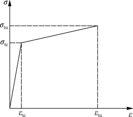
The stress-strain behaviors of different materials including ECC, the steel bar and steel shape are demonstrated in Fig.2.
(a)

(b)

(c)
The stress-strain relationships of ECC in tension and compression are described respectively by a bilinear curve (see Fig.2(a)) and a polyline curve (see Fig.2(b)), respectively. The stress-strain relationship of ECC in uniaxial tension[14]is given by
(1)
whereεtcandσtcare the first cracking strain and corresponding strength in tension, respectively;εtuandσtuare the ultimate tensile strain and corresponding strength, respectively.
The stress-strain relationship of ECC in compression[14]is given by
(2)
whereεc0andσc0are the maximum elastic strain and corresponding stress, respectively;εcpandσcpare the peak strain and corresponding stress, respectively;εcuis the ultimate compressive strain andσcuis the ultimate compressive stress (in the post-peak branch).
The steel reinforcement is described by a perfect elastic-plastic model[13]shown in Fig.2(c).
1.2 Failure characterization of SRECC beam
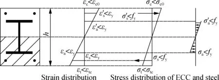
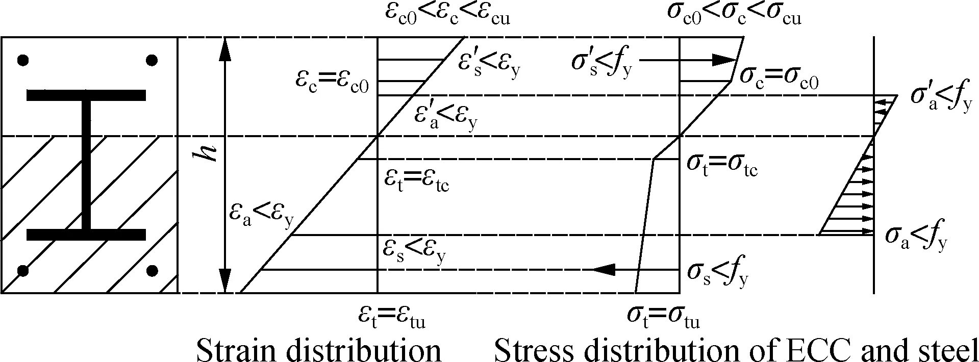
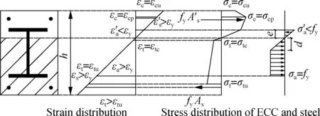
Similar to the steel reinforced concrete beams[2], the loading process for SRECC composite beam can be also divided into three stages including elastic stage, working stage, and ultimate failure stage, which are shown in Fig.3.
(a)
(b)
(c)
1) Elastic stage. At a low loading level, the deflection increases linearly with the external load, and the strain is linearly distributed along the cross section of the beam. The working condition of the beam is similar to that of an elastic beam. The stress in ECC, steel shapes and steel bars are all in the elastic stage, and the stress exhibits a linear distribution along the section. Fig.3(a) shows the stress and strain distribution of the composite beam in the elastic stage.
2) Working stage. When the strain at the utmost edge of the tension zone exceedsεtc, ECC starts to enter the strain hardening stage accompanied by multiple tiny cracks appearing in the tension zone. Due to the high ductility and excellent crack controlling ability of ECC, the composite beam presents more dense cracks with small crack spacing. During this stage, stiffness reduces slightly due to the appearance of the multiple tiny cracks. Compared with steel reinforced concrete beams, the multiple fine cracks, owing to the bridging effect of fibers, can not only prevent stress change in the steel reinforcement at the cracks but also provide a high effective moment of inertia, so no obvious change of the cross section curvature will be found. In this stage, the steel shape and steel bars maintain linear elasticity and ECC in the compression zone begins to enter the elastic-plastic stage as shown in Fig.3(b).
3) Ultimate failure stage. In theory, two types of possible flexural failures of the SRECC beam can be expected, i.e. ECC crushing failure after steel yielding and ECC crushing failure without steel yielding. Generally, the second is a typical brittle failure mode, and can be prevented by choosing a reasonable amount of steel bar or steel shape. Therefore, the failure mode (see Fig.3(c)) of ECC crushing after steel yielding will be analyzed in depth in the following section.
With the further increase of external loading, steel bar and steel shapes in the tension zone yield successively. Strain increases more quickly than stress, and a sudden increase of the cross section curvature and deflection occurs during the process. However, the external load still increases with the curvature after the tensile steel reinforcement enters the yielding stage due to development of yielding of steel web. Flexural cracks continue to propagate towards the upper side of the beam until crushing of ECC in the compression zone occurs. Compared with steel reinforced concrete beams, the SRECC beam can fully take advantage of the material property of ECC so that strength and ductility can be greatly improved. When reaching the ultimate stage, most of the ECC in the tension zone is still in the strain hardening stage except for the part outside the tensile steel bar. ECC in the tensile zone can continue to sustain tensile stress together with the steel reinforcement, resulting in the improved flexural strength of the beam. In addition, failure is initiated by the yielding of encased steel shapes or steel bars followed by the crushing of ECC. Fiber at the edge of the compression zone reaches the ultimate compression strain of ECC in the ultimate stage. It should be noted that the ultimate compressive strain of ECC is nearly twice as much as concrete, which can effectively increase the deformation ability or ductility of the beam. Meanwhile, this feature can also encourage the steel shape to develop sufficiently, which further improves the flexural strength of the SRECC beam. The ultimate load carrying capacity of the SRECC beam can be calculated based on the stress distribution along the cross section in the ultimate stage.
1.3 Derivation of load carrying capacity of SRECC beam under different conditions
As described previously, ECC has some particular properties, and the design of the SRECC beam correspondingly differs from that of the conventional steel reinforced concrete beam. For all steel reinforced beams, the ideal failure mode arises from the yielding of steel reinforcement followed by the crushing of ECC when the fiber at the edge of the compression zone reaches the ultimate compressive strain. Due to the high ductility of ECC materials, steel shapes in tension can fully develop, and the top flange of the steel shape is more likely to be in tension. Consequently, according to the location of neutral axis and stress distribution of the encased steel shapes under failure condition, five possible conditions are discussed for determining the load carrying capacity of the SRECC beam including: 1) Flange of steel shape is in tension and yield; 2) Flange of steel shape is in tension but no yield; 3) Force is zero on the flange of steel shape; 4) Flange of steel shape is in compression but no yield; 5) Flange of steel shape is in compression and yield.
Fig.4 shows the stress and strain distributions of ECC at the ultimate stage. It can be seen from Fig.4 that ECC in the compressive zone enters the phase of stress softening while partial ECC in the tension zone has exceeded the ultimate tensile strain. In the light of the assumption of the plane section, the stress along the cross section of ECC is calculated as
(3)
wherexis the distance from the extreme tension fiber to an arbitrary point along the depth of the beam;σ(x) andε(x) are the stress and strain at the height ofx, respectively;εtis the tensile strain at the edge of the cross section;E0is the initial elastic modulus of ECC;αis the reduction coefficient of the elastic modulus in the nonlinear ascent stage[15];h1is the distance from the extreme tension fiber to the point where the material reaches its ultimate tensile strain;h2is the summation ofh1and the depth of the inelastic microcracking zone;h3is the distance from the extreme tension fiber to the neutral axis;h4is the distance from the extreme tension fiber to the point where the material starts to change stiffness in compression;h5is the distance from the extreme tension fiber to the point where the material reaches the peak stress in the compressive zone;his the height of the composite beam.
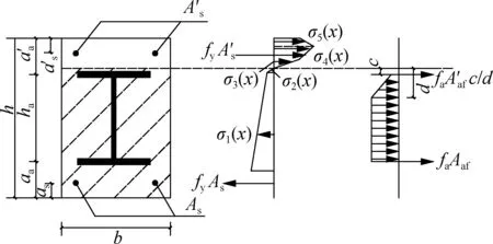
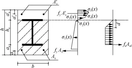
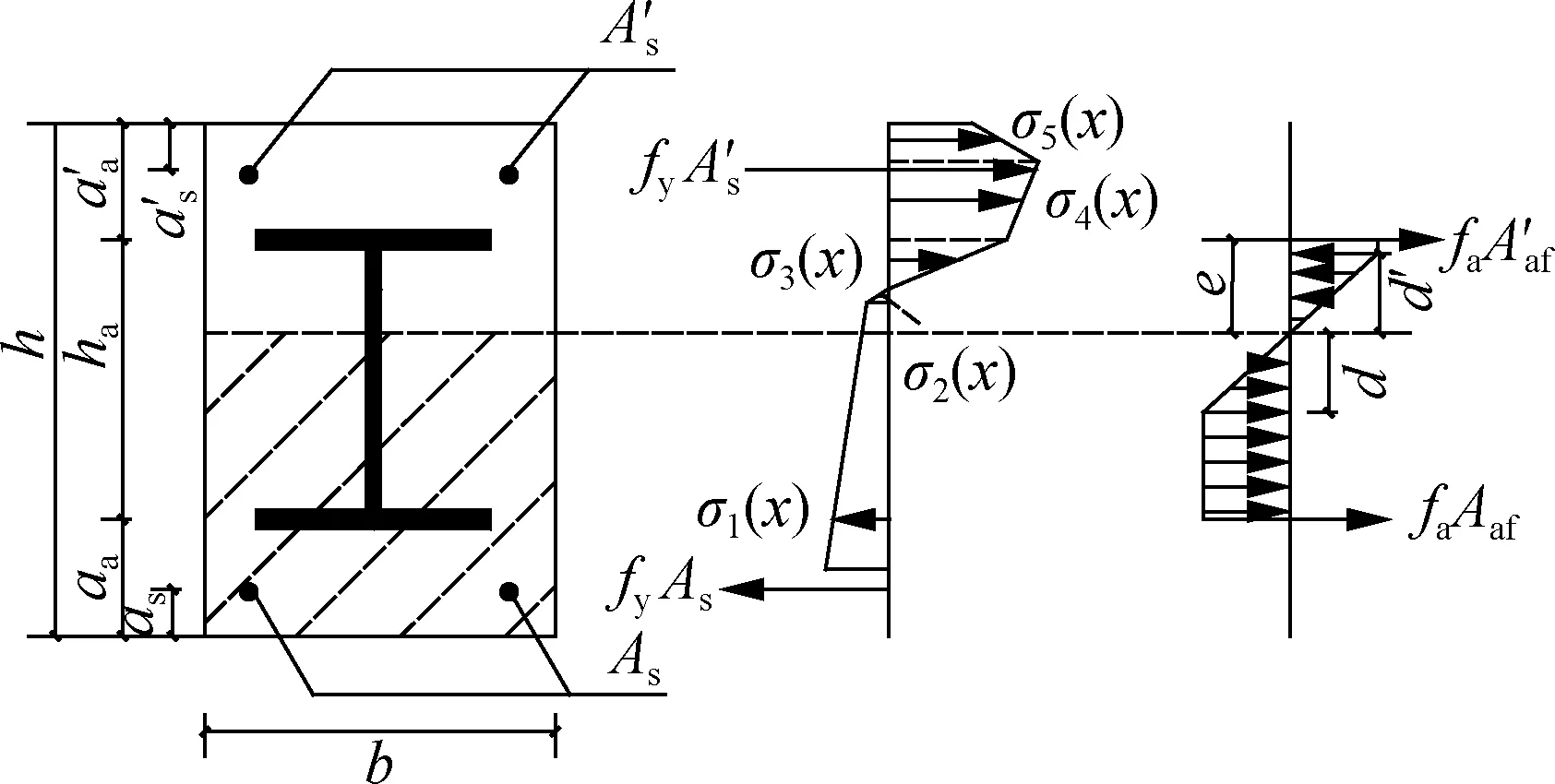
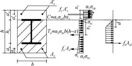
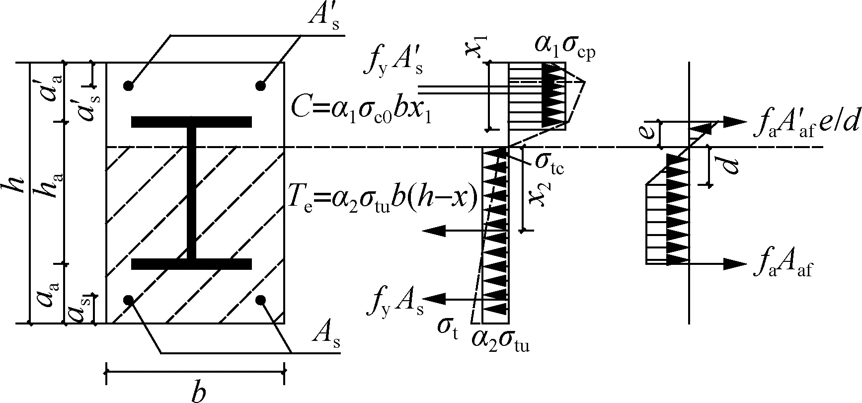
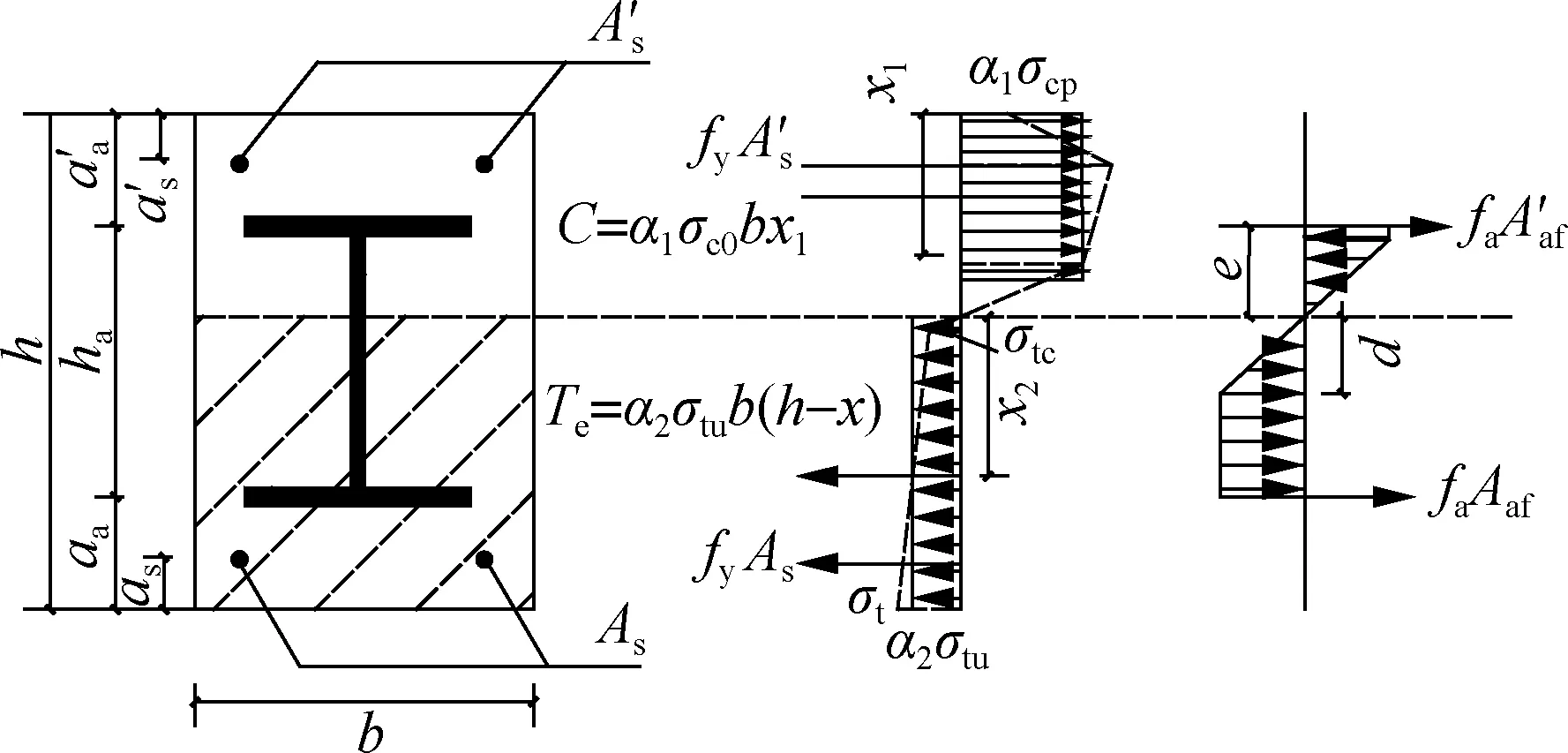
Based on the five stress states of steel shapes, the ulti-mate failure moments can be obtained and are shown in Fig.5.

Fig.4 Stress and strain distributions of ECC
1) Flange of steel shape is in tension and yield (see Fig.5(a)). According to the force equilibrium of the cross section, we have

(4)
On the basis of the moment equilibrium of the cross section, the ultimate moment can be expressed as


(5)
wherecis the distance from the neutral axis to the top flange;dis the distance from the neutral axis to the point where the steel reaches the yield strength in the tension zone.
2) Flange of steel shape is in tension but no yield (see Fig.5(b)). According to the force equilibrium and moment equilibrium, we can obtain

(6)


(7)

(a)
(b)
(c)

(d)
(e)
3) Force is zero on the flange of the steel shape (see Fig.5(c)). Obviously, from the force equilibrium condition, the following equation can be obtained and then the ultimate moment can be expressed as

(8)


(9)
4) Flange of steel shape is in compression but no yield (see Fig.5(d)). Similarly, from the force equilibrium condition, we have

(10)
and the moment can be expressed as


(11)
whereeis the distance from neutral axis to the top of the flange.
5) Flange of steel shape is in compression and yield (see Fig.5(e)). The force equation and ultimate moment are derived as

(12)
and


(13)
whered′ is the distance from the neutral axis to the point where the steel shape reaches the yield strength in the compression zone.
1.4 Simplified design method
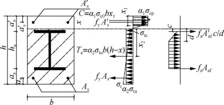
Similarly as mentioned above, the stress state of ECC varies at different depths of the cross section, usually resulting in a complex calculation formula. Therefore, the stress distribution of ECC in the tension and compression zones can be replaced with a rectangular block by ensuring the same magnitude and height of the resultant force for the stress distribution.
As shown in Fig.6, the compressive force of ECC can be given by
C=α1β1σcpbx
(14)
wherexis the height of the compression zone;α1is the ratio between the equivalent compressive strength and axial compressive strength of ECC; andβ1is the ratio between the height of the resultant compressive force and the actual compression height. Using the two equivalent principles, i.e. the effective compression force and the centroid of effective compression force remain unchangeable, the values ofα1andβ1are 0.78 and 0.89, respectively, when the fiber strain at the edge of the compressive zone reaches 0.004.
The tensile force of ECC can be given by
Te=α2σtub(h-x)
(15)
On account of the tensile stress-strain relationship which is signified by a bilinear model, the stress distribution in the tensile zone can be simplified by a trapezoid with values ofσton the bottom of the trapezoid, which can be expressed as
(16)
The resultant tensile force of ECC can be determined as
(17)
By combining Eq.(15) with Eq.(17),α2is solved as
(18)
The distance between the resultant tensile force and the neutral axis is obtained as

(a)
(b)
(c)
(d)
(e)
(19)
wherex2can be substituted byβ2(h-x),β2is the ratio between the distance from the resultant tensile force to the neutral axis and depth of the neutral axis. The values of parametersα2andβ2depend on material property, sectional dimensions and steel ratios, etc.
In view of the above discussions, the simplified calculation method is obtained as follows:

(20)
and the ultimate moment of the cross section is given by
(21)


(22)
α2σtubβ2(h-x)2+fyAs(h-as-x)+
(23)

(24)
and the ultimate moment capacity of the beam is given by
α2σtubβ2(h-x)2+fyAs(h-as-x)+
(25)


(26)
and the ultimate moment capacity is given by

faAaf(h-aa-x)
(27)


(28)
According to the moment equilibrium, the ultimate moment capacity can be simplified by
(29)

In the aforementioned equations, there is only one unknown parameterx. Hence, the computational procedure can be initiated by assuming a stress state of the cross section, and then the value ofxand the corresponding ultimate moment capacity can be calculated.
To avoid over-reinforced failure, it is worth noting that the ideal failure mode should also satisfy the following condition which is determined by strain compatibility. The condition is that both the encased steel shape and steel bar yield in tension at the ultimate stage, and we have
(30)
2 Verification of Theoretical Modeling for SRECC Beam
According to the proposed theoretical models, the moment-curvature relationship of SRECC beams can be calculated by a conventional strip method[16]. A SRECC beam is chosen to analyze the mechanical behavior of the proposed beam. The clear span of the beam is 1 800 mm with a cross section of 180 mm×250 mm. The embedded structural steel shape has a cross section of 100 mm depth by 100 mm flange breadth, web and flange thicknesses of 6 mm and 8 mm, respectively. The ratio of reinforced bars is 1% for the SRECC beam. The beam is designed with the stirrup with the diameter of 8 mm and the spacing of 100 mm to prevent premature shear failure. The material constitutive models are stated in the above section. The elastic modulus of the steel reinforcement is 206 GPa, and the yield and ultimate strength of the encased steel shape and steel bars are 270 and 552 MPa, respectively. The compressive strength of ECC and concrete are 22 MPa, while the elastic modulus of ECC and concrete are 14.3 and 32 GPa, respectively. The beam is loaded under four-point bending with a span of 1 800 mm between two supports. The external loads are applied symmetrically with 500 mm from the supports.
To verify the validity of the proposed theoretical modeling, the flexural behavior of the SRECC beam is simulated with the software ABAQUS. In this model, it is assumed that no relative slip occurs between the steel bars or steel shapes and ECC. To avoid stress concentration, four steel plates are fixed on the loading and supporting zones. The finite element model of the SRECC beam is illustrated in Fig.7.

Fig.7 Finite element model of steel reinforced ECC composite beam
Fig.8 depicts the comparison of the moment-curvature curves from the theoretical and simulation results. It can be seen that the theoretical results show a good consistency with the simulated results, indicating that the theoretical model can be used to predict the mechanical property of SRECC composite beams.
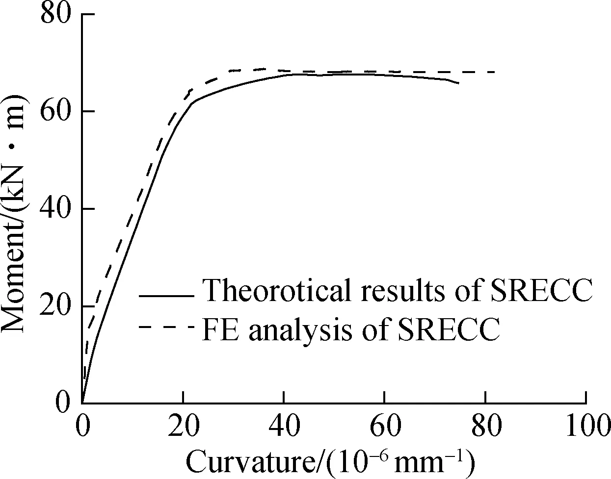
Fig.8 Comparison between simulation results and theoretical results
3 Parametric Study
The flexural behavior of the composite beam is related to some key parameters, such as matrix type, encased steel shape ratios, longitudinal reinforced bar ratios, compressive strength and ultimate tensile strain of ECC. Thus, a parametric study was carried out to discuss the effects of the parameters.
3.1 Effect of matrix type
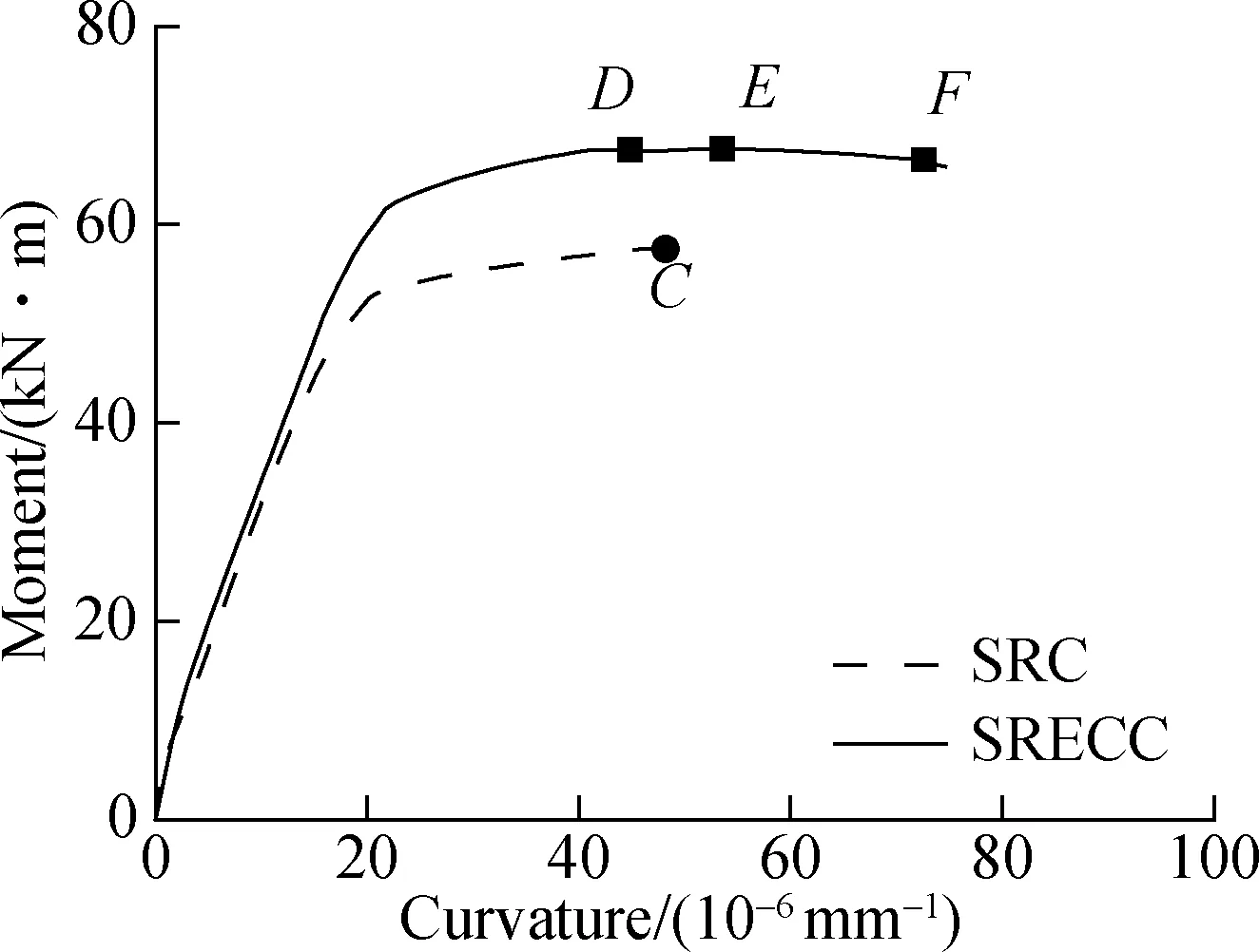
For the specimens of steel reinforced concrete (SRC) beam and SRECC beam, all the design parameters are identical except for the material type of the matrix. The constitutive relationship of concrete under uniaxial compression is adopted according to the Chinese Code for Design of Concrete Structure (GB 50010—2010)[8], and the tensile strength of the concrete is ignored. The moment-curvature curves between SRECC beam and SRC beam are exhibited in Fig.9.

(a)
(b)
It can be observed from Fig.9(a) that due to the lower elastic modulus of the ECC, the initial stiffness of the SRECC beam is smaller than the SRC beam. However, a sudden curve change of the SRC beam can be seen at a curvature of 0.57×10⁻⁶(pointA) due to the cracking of concrete in the tensile side, while no obvious change can be seen in the SRECC beam. The stiffness of the SRECC beam is similar or even slightly larger than that of the SRC beam when the curvature is larger than 0.57×10⁻⁶. This can be explained by the fact that the multiple fine cracks formed in ECC components lead to a high effective moment of inertia, which compensates for the lower elastic modulus. Then, the moment-curvature curves increase linearly before the yielding of steel bars. After that, the slope of the curves changes suddenly, as shown in Fig.9(b). As for the SRC beam, the flexural capacity increases gently due to the process of steel web yielding from bottom to top until concrete in the compression zone reaches the ultimate compressive strain. For the SRECC beam, although the peak compressive strain of ECC is larger than that of concrete, the curvature of pointDwhen the strain reachesecpis smaller than pointCwhen the concrete reaches the ultimate strain. This is because ECC in tension can provide tensile resistance to the beam, which reduces the neutral axis height. When the cross section reaches the maximum moment (pointE), the flexural load capacity of the SRECC beam can reach 67.7 kN·m, which is 17.5% larger than that of the SRC beam. As shown in Fig.9(b), pointEis located between pointDand pointFwhen strain reachesecu, and the moment difference of pointD, pointEand pointFis quite small. The small change in the moment is because the plastic development of the steel shape for the SRECC beam can be more sufficient than that of the steel reinforced concrete beam due to the higher ultimate compressive strain of ECC material. Therefore, the ductility of the SRECC beam is correspondingly greater than that of the SRC beam. Substituting concrete with ECC can provide a significant enhancement in both the load carrying capacity and ductility.
3.2 Effect of encased steel shape ratio
The influence of the ratio of encased steel shapes on the flexural behavior can be evaluated by changing the area of encased steel shapes, as shown in Fig.10. It can be found that increasing the ratio of encased steel shapes leads to the increase of stiffness and ultimate bending moment. However, there is an apparent decrease of ultimate curvature with the increase of the steel shape ratio. It may be explained by the fact that a higher steel shape ratio leads to an enhancement of the tensile zone, resulting in the neutral axis shifting downwards. Therefore, the ultimate curvature will decrease when the stain at the edge of the compressive zone reaches the ultimate compressive strain of ECC.
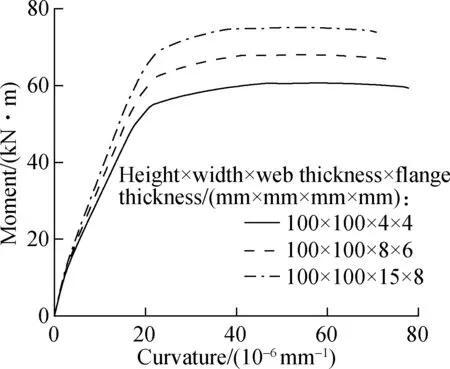
Fig.10 Moment-curvature curves with different encased steel shape ratios
3.3 Effect of longitudinal reinforced bar ratio
Fig.11 shows the moment-curvature curves of the composite beams with different longitudinal bar ratios. As expected, the specimen with more reinforced bars achieves a much greater stiffness and ultimate bending moment. The increase is more pronounced than the increasing ratio of encased steel shapes, indicating that increasing longitudinal bar ratio is an effective measure to improve the stiffness and ultimate moment capacity of the SRECC beam.
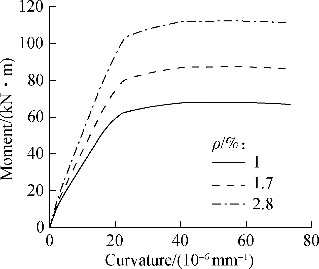
Fig.11 Moment-curvature curves with different longitudinal reinforcement ratios
3.4 Effect of compressive strength of ECC
The parametric study is carried out by changing the compressive strength of ECC from 20 MPa to 40 MPa. Fig.12 depicts the effect of compressive strength of ECC on the ultimate moment and curvature of the SRECC beam. Both the ultimate moment and curvature increase with the increase of compressive strength. This may be because increasing ECC compressive strength will result in the increase of the tensile zone, which means more steel shapes locate in the tensile zone and the flexural bending moment can be increased.

Fig.12 Moment-curvature curves with different ECC strengths
3.5 Effect of ultimate tensile strain of ECC
Due to the influence of material composition and fabrication process, the ultimate tensile strain of ECC may range from 1% to 7%. In this study, a parametric study with various values of ultimate tensile strain of ECC is carried out to appraise the influence on the ultimate moment and curvature of the SRECC beam. It is clearly seen from Fig.13 that varying the ultimate strain of ECC results in a very limited variation in both the ultimate moment and ultimate curvature. The main reason is that a large proportion of ECC at the tensile zone does not exceed the ultimate strain even when the ultimate tensile strain is 1.5%, and stress softening of ECC will not occur. It can be concluded that the increase of the ultimate tensile strain has little contribution to the ultimate moment and curvature, and ECC with 1.5% ultimate strain can provide a sufficient tensile deformation ability for the SRECC beam.
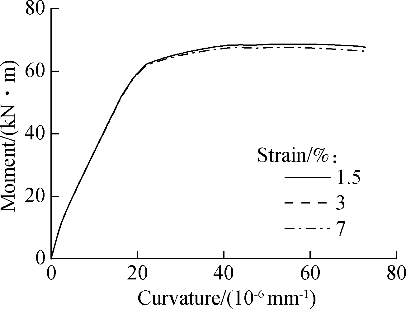
Fig.13 Moment-curvature curve with different ultimate tensile strains
4 Conclusions
1) Theoretical models and a simplified design method of the SRECC beam are proposed based on the basic assumption and the constitutive relationships of materials, and the design method provides a simple yet reasonable accurate prediction for the mechanical performance of the SRECC beam.
2) For a steel reinforced ECC beam, substitution of conventional concrete with ECC can not only limit the generation of large cracks and prevent the encased steels from corrosion, but also improve the strength and ductility of the composite beams.
3) The increase of steel shape ratio, longitudinal bar ratio and ECC compressive strength can effectively improve the bending stiffness and ultimate moment of the SRECC beam, while the ductility behaves differently with various parameters. The excessive ratio of steel shapes usually results in a decline in ultimate curvature, while the increase of ECC compressive strength can improve the ultimate curvature to some extent.
杂志排行
Journal of Southeast University(English Edition)的其它文章
- Influence of image data set noise on classification with a convolutional network
- A low-cost personal navigation unit
- Compact passing algorithm for signalized intersection management based on vehicular network
- Analysis of conflict factors between pedestrians and right-turning vehicles at signalized intersections
- Effect of contract choice on upstream carbon emission reduction considering carbon taxation
- Multi-relaxation-time lattice Boltzmann simulation of slide damping in micro-scale shear-driven rarefied gas flow
