A low-cost personal navigation unit
2019-04-04CaiTijingXuQimengZhouDaijin
Cai Tijing Xu Qimeng Zhou Daijin
(School of Instrument Science and Engineering, Southeast University, Nanjing 210096, China)
Abstract:For the purpose of positioning in various scenes, including indoors, on open road, and side street buildings, a low-cost personal navigation unit is put forward. The unit consists of a low-cost MEMS(micro-electro-mechanical system) accelerometer, a gyroscope, a magnetometer and a GPS(global positioning system) chip, and it is capable of switching modes between indoor and outdoor situations seamlessly. The outdoor mode is MIMU(MEMS-inertial measurement unit)/GPS/magnetometer integrated mode and the indoor mode is MIMU/magnetometer integrated mode. The outdoor algorithm uses the extended Kalman filter to fuse data and provide optimum parameters. The indoor algorithm is dead reckoning, which uses vertical and forward accelerations to judge steps and uses a magnetometer to define heading. The two-axis acceleration data is used to calculate the adaptive threshold and estimate the confidence value of the steps, and when the confidence of both two axes data meet the conditions, the steps can be detected in the adaptive time windows. The detection precision is more than 95%. An experiment was conducted in complex situations. The experiment participant wearing the unit walked about 1 600 m in the experiment. The results show that the positioning error is less than 0.2% of the total route distance.
Key words:personal navigation; integrated navigation; dead reckoning; extended Kalman filter
As a type of novel autonomous navigation technology, personal navigation is widely used in the military and civilian fields, especially for tasks including individual combat, emergency rescue, reconnaissance and expedition, etc. Although the most common algorithm for personal navigation is MIMU/GPS integrated navigation, it is unable to continue positioning in the locations where the satellites are sheltered such as cities, valleys, and forests[1]. Besides, the SINS algorithm with low-accuracy MEMS sensors are unreliable for the significant accumulative error. Therefore, additional sensors are necessary in the process of positioning and compassing based on MIMU/GPS integrated navigation. Xu[2]put forward a kind of MIMU/GPS/magnetometer integrated navigation system in 2014, which behaved better than MIMU/GPS integrated navigation outdoors. Aggarwal et al.[3]suggested heuristic elimination of gyro drift in GPS-denied conditions, estimating heading angle by matching IMU-derived heading to the direction of the streets map in the database, whose precision is 1%. Guo et al.[4]suggested a personal navigation system using an inertial measurement unit and a MEMS-based ground reaction sensor array (GRSA), which provides a zero-velocity update for the IMU, and the system showed high accuracy both in vertical and in-plane positioning.
In terms of indoor location, the positioning algorithm can be divided into four categories: 1) ZUPT (zero velocity update), using velocity error at stance phase as an observation measurement in the Kalman filter to correct position errors, velocity errors and attitude errors[5]; 2) Wireless positioning, usually based on RSSI or TDOA, calculating the receiver’s location through the estimated distance between targets and the receiver; 3)Database matching, for instance, a raised typical indoor location system using Wi-Fi fingerprint matching technique[6]; 4) Dead reckoning, identifying pedestrian steps through inertial sensors[7]. Recent research results show a tendency toward combining different methods, for instance, a combination of ZUPT and indoor map matching[8], a combination of ZUPT and Wi-Fi received signal strength indicator[9], a combination of dead reckoning and RFID[10], and a combination of dead reckoning and map matching[11-12]. The methods above have a common point that they are based on the autonomous navigation algorithm, with external information (map, Wi-Fi, RFID, etc.) as an auxiliary. The addition of external information helps limit errors and improves positioning, which produces a better positioning effect indoors.
This paper proposes a kind of low-cost personal navigation unit which works in both outdoor and indoor locations. In the event of qualified GPS signals, the MIMU/GPS algorithm is adopted, while on other occasions the MIMU/magnetometer and pedometer are integrated. The experiments show that the unit operates effectively and switches between the two modes seamlessly.
1 Description of Hardware
The hardware includes a navigation computer and data acquisition module. Fig.1(a) shows that the navigation computer consists of a DSP and a FPGA, which are connected through EMIFA. The FPGA connects peripherals and sends calculation results to the PC through UART, while DSP runs the navigation algorithm. The data acquisition module is composed of an accelerometer, a gyroscope, a magnetometer and a GPS board. The frequencies of the inertial data and GPS are 100 and 1 Hz, respectively. The personal navigation unit is immobilized on the pedestrian’s waist while walking, and the result is shown on the PC monitor. Fig.1(b) is the picture of the unit.

(a)

(b)
2 Mathematical Model of Outdoor Positioning
In terms of outdoor positioning, the MIMU, GPS and magnetometer are integrated.The initial attitude is determined by the accelerometer and magnetometer. In the algorithm, the extended Kalman filter fuses GPS, magnetometer and positioning data, and then the errors of the accelerometer, gyroscope and navigator can be estimated. After the data is corrected, the navigation results are outputted.
2.1 The system state equation
The extended Kalman filter state equation is

(1)

2.2 The system observation equation
The MIMU output parameters are corrected with the help of GPS and magnetometer data, that is, on the occasions when qualified GPS signals, GPS velocity, the position and heading angle are used and on other occasions, the magnetometer provides a heading angle. The observation equation is
(2)
whereLS,λS,hS,VSE,VSN,VSU,φSare the position, velocity and heading angle calculated through the SINS navigation algorithm;LG,λG,hG,VGE,VGN,VGU,φGare the GPS positions, velocity and heading angle;φMis the magnetic heading angle obtained from magnetometer;δL,δλ,δh,δVE,δVN,δVU,δφare the errors of MIMU positions, velocity and heading angle;δLG,δλG,δhG,δVGE,δVGN,δVGU,δφGare the errors of GPS positions, velocity and heading angle;δφMis the error of magnetic heading angle;HandVare the system’s measurement matrix and measurement noise matrix, respectively.
3 Mathematical Model of Indoor Positioning
In terms of indoor positioning,the dead reckoning algorithm is adopted. According to accelerometer data, the adaptive threshold is calculated and the step confidence is estimated, and then the step can be detected in the adaptive window. In addition, step length can be estimated according to the step frequency based on the step frequency-length linear model. Finally, indoor positioning is realized with step number and step length.
3.1 Analysis of step data
The output of the 3-axis accelerometer mobilized on the pedestrians’ waist shows that the acceleration data changes cyclically, especially the vertical and forward accelerations. However, multiple peaks and valleys exist in each cycle because of factors including noise and error. Therefore, the acceleration data of both axes should be taken into account for the issue of steps detection.
3.2 Adaptive threshold
The vertical acceleration fluctuates periodically, one cycle matching one step. Here is the detection method, first we compare vertical acceleration to a predetermined threshold, and then we regard the time point that acceleration passes through threshold from bottom to up as the beginning of a step. Considering that multiple extremums may appear in one period since the raw data rises and falls sharply, the method may miss a step or overcount.
In each time window, the high thresholdTH, middle thresholdTM, and low thresholdTLcan be written as
(3)
(4)
(5)
Suppose that there areilocal maximums,p1,p2,…,pi, andjlocal minimums,v1,v2,…,vj, in the time window.TH,t-1andTL,t-1are the high threshold and low threshold in the previous time window. The three thresholds change constantly with the pedestrian’s walking steps. In particular, the methods calculating adaptive thresholds on the vertical and forward axes are the same. It is relatively reliable to use the middle threshold as a standard, so the unit regards the time point when the vertical acceleration passes through middle threshold upward as the beginning of a step.
3.3 Estimation of degree of step confidence
The unit distinguishes between two states, walking and rest, by estimating the degree of step confidence twice. The purpose of the first estimation is to judge the trend of data in the window roughly and ignore the windows in which steps almost impossibly exist. Standard deviation is a typical statistical argument reflecting the degree of dispersion. Greater standard deviation matches sharper fluctuation of the acceleration data in a window, that is, a step is more likely to exist. However, the large amount of computation in calculating standard deviation affects the efficiency of the algorithm, so the fluctuation is represented by
(6)
The calculation ofsyis similar to Eq.(6). It is certain thatszandsyapproach zero when a pedestrian rests or barely moves. From this, the degrees of step confidence on the two axes,cz1andcy1, will be set to be 1 or clear to 0 by the rule
(7)
(8)
The second estimation is executed if bothcz1andcy1meet the condition, and the degrees,cz2andcy2, are defined by the difference between high and low thresholds. The rule can be written as
(9)
(10)
qi=THi-TLii=y,z
(11)
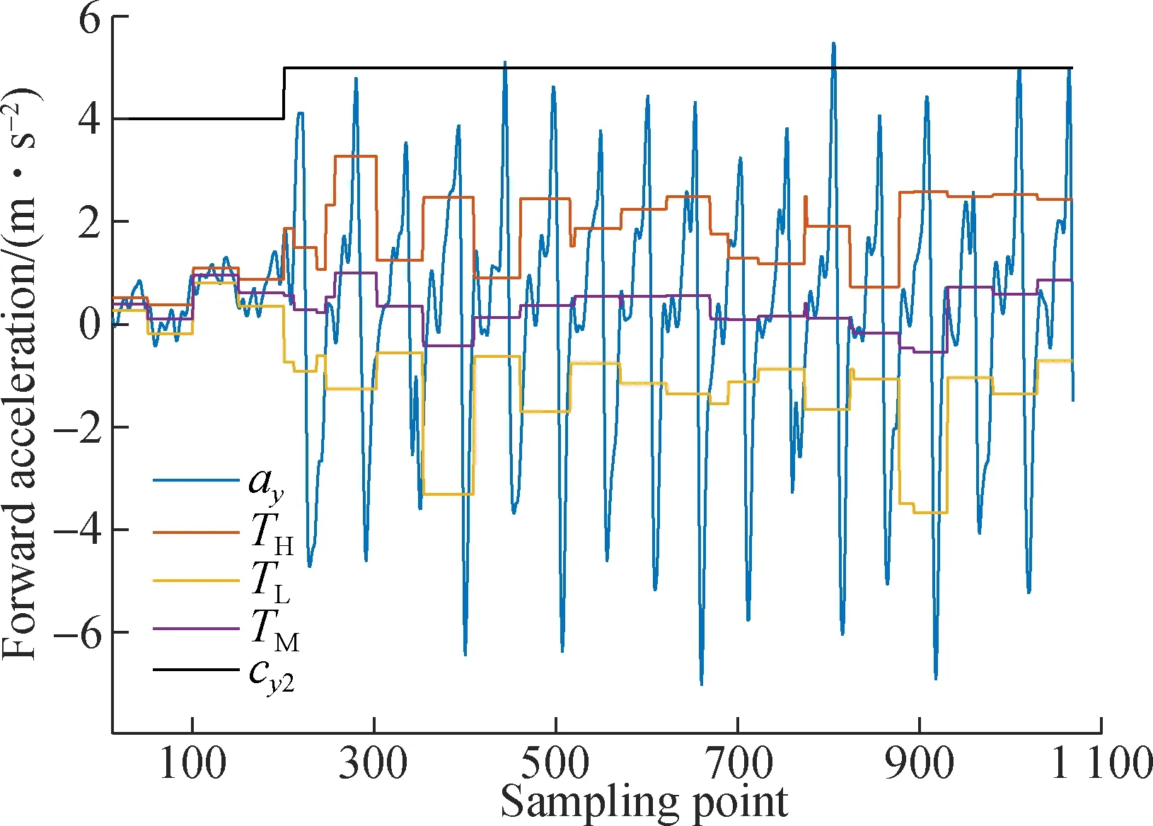
wherTHandTLare the high threshold and low threshold of acceleration in the time window, respectively. The thresholds 0.9 and 1.1 are empirical values. Then, the window in which the number of steps changes can be detected. Fig.2(a) and Fig.2(b) show the degree of confidence of vertical and forward accelerations.
If bothcz2andcy2are set, the vertical acceleration data will be traversed and the step will be detected further. The condition of the step can be written as
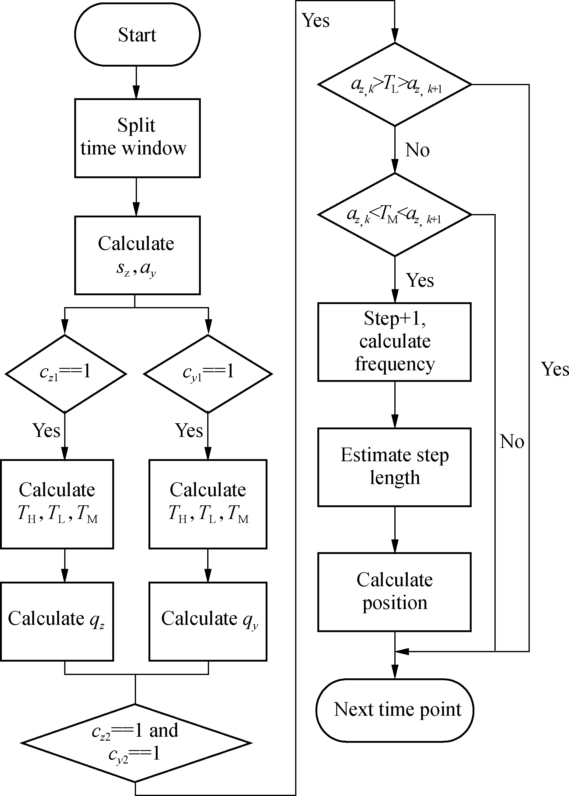
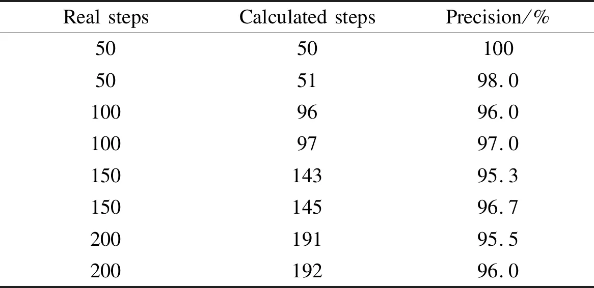
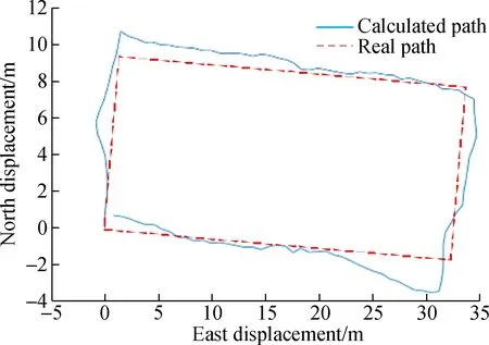
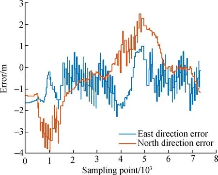
az,k (12) where the sampling pointk+1 is the time when vertical acceleration passes through the middle threshold upward, that is, the beginning of a step. Although the algorithm does not miss a step if the passing point is in the time window, the problem is that the step will be missed if the point is exactly right on the boundary of the time window. Therefore, an adaptive time window is adopted to make the step point appear in the middle as much as possible, which means that a time window with changing steps will be terminated if the condition (a) (b) az,k>TL>az,k+1 (13) is met. The pointk+1 is the time when vertical acceleration passes through the low threshold downward, and a new time window will be fit from dataaz,k+1anday,k+1. The data in the new time window is {az,k+1,…,az,N,…,az,N+k} and{ay,k+1,…,ay,N,…,ay,N+k}, whereNis the size of the window. In Fig.3, the blue curve is the vertical acceleration data acquired while walking, the black polyline represents middle threshold, and the red split line represents the detected step. Since the time window is adaptive, the width of the window varies. The figure shows that the result of the algorithm is quite effective. According to the dead reckoning theory, the walking process can be separated into steps, each one projecting to east and north under the heading angle. As the duration of a step is quite short, it is supposed to be a linear motion, and the pedestrians’ position is obtained by accumulating all of the steps. Fig.3 Graphical effect of pedometer The position on the next moment, (Ln+1,λn+1), is calculated on the basis of dead reckoning according to the previous position, (Ln,λn), which can be modeled by (14) (15) whereφMis the magnetic heading angle;rnis the curvature radius of the earth on the north-axis;reis the curvature radius of the earth on the east-axis;lis the length of a step which is estimated by the frequency. There is a linear relationship between the lengthland frequencyfof a step, which can be written as l=αf+β (16) whereαandβare coefficients of the linear equation, which are obtained from the fitting curve by several tests. As Fig.4 shows, the vertical and forward acceleration data are put into two 50-length buffer arrays, and the algorithm is executed when the arrays are full. The first estimation of the confidence degree is obtained according to Eqs.(7) and (8), and then the adaptive thresholds are obtained according to Eqs. (3) to (5). The number of steps is probably changing in the current time window if both of the second estimations meet the condition, and the changing point can be detected when vertical acceleration passes throughTMupward. Finally, the current position is calculated based on the step number, length and magnetic heading angle. The instrument chooses GPS/SINS integrated navigation mode when outdoors, and it changes to the dead reckoning algorithm when indoors, that is, there is no GPS signal. Fig.5 shows the switching method between outdoor and indoor algorithms. Fig.4 Description of the dead reckoning algorithm Fig.5 Graphical description of switching> The GPS signal is checked every second (GPS frequency is 1 Hz). Once the signal is not available, there is a variableKcounting time. IfKis less than 5 which means that missing time is less than 5 s, the GPS/SINS integrated navigation algorithm can still work. Otherwise, the system changes to the dead reckoning algorithm. As Fig.6 shows, the participant walks from an open environment into a building, and wanders for a while indoors. The diagram can roughly indicate the person’s path, so the switching algorithm is acceptable. Fig.6 Diagram of switching from outdoors to indoors Before testing the navigation algorithm, the pedometer was tested since the accuracy of the counting steps is essential for the navigation result. The experiment participant wearing the unit walked on the path at different lengths, and the steps were counted and compared to the steps outputted from the pedometer. The results in Tab.1 show that the algorithm counts steps correctly and the precision is greater than 95%. Tab.1 Results of the pedometer experiment Afterwards, an experiment testing the indoor positioning effect was performed, in which the participant wearing the unit walked indoors along a specified route. The participant started from point (0, 0), and the route shaped a rectangle as Fig.7(a) shows. The error during the route can be seen in Fig.7(b). The walking distance is about 80 m, and Tab.2 shows that the root square errors in east and north directions are 0.71 and 1.34 m, respectively. m Tab.2 Root square errors in the indoor experiment The comprehensive experiment was performed on campus. Both indoor and outdoor algorithms could be tested in this situation, because there were buildings and tree shade and GPS signal could be sheltered. The participant wearing the unit walked around campus, and Fig.8(a) is the trace plot on the Google map. (a) (b) (a) (b) According to the experiment, GPS could not position during loss of a satellite signal while the pedestrian passed across the courtyard, under tall buildings or tree shade. However, the unit was able to adapt to indoor situation and position with the help of the accelerometer and magnetometer. The errors during the experiment can be seen in Fig.8(b), and the maximum error in east and north directions is 8 m. The root mean square errors in east and north directions are listed in Tab.3. The results show that the error rate of the unit is less than 0.2% of the total route distance, which is about 1 600 m. This proves that the unit is able to position correctly in most occasions. m Tab.3 Root square error in the comprehensive experiment 1) The personal navigation unit realizes long-term positioning indoors and outdoors for a pedestrian, and is able to switch between two modes when the situation changes. 2) The outdoor positioning algorithm is MIMU/GPS/magnetometer integrated navigation, using the position, velocity and heading angle as an observation vector in the extended Kalman filter. 3) The indoor positioning operating mode integrates the MIMU/magnetometer, and the algorithm is dead reckoning. With the vertical and forward acceleration data, the algorithm is able to detect the steps according to the adaptive threshold and degree estimation of step confidence. Finally, positioning is realized by magnetometer determining heading. 4) The experiment shows that the unit’s error rate is less than 0.2% of the total route distance, which proves that the realization is effective and beneficial for research in fields of personal navigation.3.4 Adaptive time window

3.5 Dead reckoning

4 Switch Between Two Modes


5 Results and Discussion



6 Conclusions
杂志排行
Journal of Southeast University(English Edition)的其它文章
- Influence of image data set noise on classification with a convolutional network
- Flexural behavior of steel reinforced engineered cementitious composite beams
- Compact passing algorithm for signalized intersection management based on vehicular network
- Analysis of conflict factors between pedestrians and right-turning vehicles at signalized intersections
- Effect of contract choice on upstream carbon emission reduction considering carbon taxation
- Multi-relaxation-time lattice Boltzmann simulation of slide damping in micro-scale shear-driven rarefied gas flow
