Inlet flow disturbance effects on direct numerical simulation of incompressible round jet at Reynolds number 2500
2018-11-24ZejingHuYonglingZhngZuojinZhu
Zejing Hu, Yongling Zhng, Zuojin Zhu,
a Faculty of Engineering Science, University of Science and Technology of China, Hefei 230026, China
b Anhui Xiang Shui Jian Pumped Storage Co., LTD, Wuhu 241083, China
Keywords:Incompressible round jet Jet core cone Biased upwind finite difference Swirling strength intermittency factor Accurate projection method
ABSTRACT This letter reports inlet flow disturbance effects on direct numerical simulation of incompressible round jet at Reynolds number 2500. The simulation employs an accurate projection method in which a sixth order biased upwind difference scheme is used for spatial discretization of nonlinear convective terms, with a fourth order central difference scheme used in the discretization of the divergence of intermediate velocity. Carefully identifying reveals that the inlet flow disturbance has some influences on the distribution pattern of mean factor of swirling strength intermittency. With the increase of inlet disturbance magnitude jet core cone slightly shortens, observable differences occur in the centerline velocity and its fluctuations, despite the negligible impacts on the least square fitted centerline velocity decay constant (Bu) and distribution parameter (Ku) for velocity profile in self-similar region.
In many practical applications turbulent jets play crucial roles, for instance in the thermodynamical mechanisms of combustion, heat and mass transfer. As a prototype of free flow, turbulent jet has been studied frequently, there are a large number of publications and reviews. Some early reviews were reported[1-3], with a recent review given in Ref. [4].
To confirm the behavior of jet similarity at least asymptotically, experiments were conducted by Ref. [5-7]. But the universality of jet similarity can still depend on other factors, such as the initial conditions [8]. Using three distinct acceleration
schemes of linear, quadratic, and exponential to increase the nozzle exit velocity by an order of magnitude, Zhang et al. [9]studied acceleration effects on turbulent jets in a series of flow visualization experiments. They found that as the flow accelerated, a discernible front was established. Based on the scaling of centerline velocity in steady jets, a model appears to correctly predict the time dependence of the front position. Some others experimental results were reported in Refs. [10-14]. For instance,Abdel-Rahman et al. [10] measured the velocity field of turbulent round air jet flows to study the relative influence of using a wall at the jet exit plane on the jet behaviors and characteristics.The dispersion and mixing of passive scalar (temperature) fluctuations in a turbulent jet was studied by Tong and Warhaft [14],for which the centerline velocity fluctuation at Reynolds number 18000 was reported.
To study the inflow condition effect on far field self-similar region of a round jet, the direct numerical simulation (DNS) of a spatially developing free round jet at a low Reynolds number ofwas performed by Boersma et al. [15]. They found the evidence in support of the suggestion by Ref. [8] that the details of self-similarity depend on the initial conditions, implying that there may exist no universally valid similarity scaling for the free jet.
A brief literature review has been reported elsewhere [16]. In the present study, to present a more specific insight of turbulent intermittency from views relating to variations of vortical structures, prediction of swirling strength intermittency factor with DNS of incompressible jet at Reynolds number 2500 is carried out. For this purpose, a sixth order biased-upwind difference scheme (BUDS) and a fourth order central difference scheme are developed and used in an accurate projection numerical method for the DNS. The BUDS is also used in seeking the 1+1 Burgers equation under definite conditions to inspect its application feasibility at first and then used in the DNS of the jet flow.The numerical results have been checked by a step ratio approach [17, 18], and validated by the existing experimental and DNS results, hence the checking of grid independence is omitted. We will start our description from governing equations and terminate by several concluding remarks.
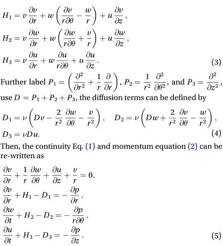
In Fig. 1(a), a sketch of the jet geometry and the cylindrical coordinate system are illustrated. Let us assume that the fluid is emitting the computational domain through an orifice in a wall with a jet speed. The fluid flow enters into free space without confining walls. While moving downstream, the jet cross section increases due to entrainment, ambient fluid has to enter the jet region [19]. This entrainment is generated by small pressure differences between the surrounding and the jet flow. The flow is assumed to be isothermal and incompressible and is thus governed by the following equations based on the conservation of mass and momentum:

The computational domain and its boundaries are shown in Fig. 1(b). The three types of boundaries: the inflow, outflow, and lateral boundary, require distinguished boundary condition.
At the inflow boundary of the jet all three velocity components are specified, and the pressure is left free. For the specification of the velocity, we distinguish between the area inside and outside the orifice, i.e.,
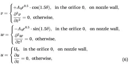

Fig. 1. a A sketch of the jet geometry plus cylindrical coordinate system, denotes the radial direction, denotes the axial direction, with the circumferential direction omitted. b A sketch of the computational domain. , and.
At the lateral boundary, by assuming the radial derivative for radial velocity componentis zero, using the so-called tractionfree boundary condition [15, 20], we can derive that the second order derivative should be vanished, that means for,

At the flow centerline, the jet symmetry requires that for

At the outflow boundary we use a so-called convective boundary condition [15], foras

When circumferential period is assumed to be, the periodic boundary condition in the circumferential direction is given by

Such assumption permits to use less grids in the circumferential direction as compared that for the case without the period half shortening.
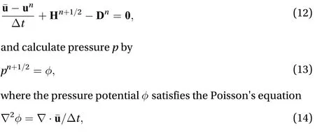
The governing Eq. (5) of jet flow were discretized by a finite difference method in a staggered grid system. An accurate projection method [21] is used for the DNS. Now just a brief description is described below. Let the intermediate velocity vector, the pressure potential, and the time level be, and, respectively. Defineandthen let

Computational parameters are shown in Table 1. The jet Reynolds numberReis defined by orifice diameter, orifice velocity, and kinematic viscosity of fluid. The orifice wall thicknessis assumed to be 0.025. Respectively, the lateral and outflow boundaries are given byand,with the mesh numbers in radial and axial directions set atand. While the mesh number in circumferential direction is set at, as we have made the assumption of period half shortening.
The seventh column of Table 1 shows the step ratiocalculated by the approach of Smirnov et al. [17, 18]. The step ratiorefers to the ratio of maximal allowable number of time steps for the problem and the actual number of time steps used to obtain the result. For, using the time step shown in the sixth column of Table 1,equals 3.158 which is larger than unity. As reported [17, 18],characterizes reliability of results to determine the limit of the simulations. The higher the value of, the lower the accumulated error is. Asapproaches unity, the error tends to a maximum allowable value. As the reliability of numerical results is evaluated by a step ratio approach [18],the relevant verification is done in comparison with existing measured and calculated data, the DNS is conducted without checking grid independence.

Fig. 2. A sketch for discretizing at grid with a sixth BUDS, a for
Using the accurate projection method given above, the DNS of the incompressible jet at Reynolds number 2500 was carried out in a personal computer with a memory of 3.2 GB and CPU frequency 3.30 GHz. The DNS is started from a postulated lamin-ar velocity field, as soon as the flow patterns have appeared some turbulent properties, the instantaneous flow field is saved and the time in the unit ofis changed and reset at.For statistical analysis of jet flow field, further simulations are carried out for 100 time scalesto achieve DNS data. Such a further simulation needs CPU time about 64.5 h. As the total step number is, the per time step CPU time is about 3.715 seconds.
The DNS predicts mean values of velocities on the basis of time-circumferential (-) average. The inverse of mean centerline velocity in the unit of orifice velocity () plotted as a function of distance to the orifice () is shown in Fig. 3(a),where the yellow filled black circles show the DNS results obtained by solving the Navier-Stokes equations in spherical coordinates with a method briefly described by Ref. [15], the squares and plus-symbols are the existing measured data [5, 7].For self-similar jet, as shown by blue deltas in Fig. 3(a),can be described empirically [7]

Using least squares method to analyze the present DNS data in the far regionz≥12, when, it is estimated thatand 5.846 respectively for,and 0.1382 labeled by DNS1, DNS2, and DNS3. The decay constant is excellently well predicted in comparison with that value 5.9 predicted by Boersma et al. [15] and the experimental data 5.9 of Hussein et al. [7].
When the velocity profile is assumed to be Gaussian,

By averaging the axial velocity over the rangeby means of a least-squares method, the numerical data by DNS show that the distribution parameter=75.09, 75.59, and 74.17 for DNS1, DNS2 and DNS3 respectively, see in Fig. 3(b), an excellent agreement as compared with the experimental data() of Panchapakesan and Lumley [6], and DNS data() in Ref. [15].

Table 1 Parameters of the round jet flow used in the DNS.
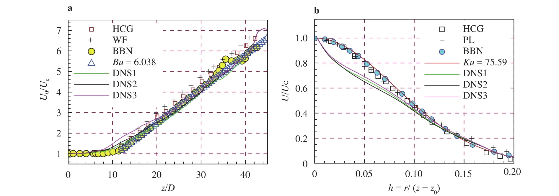
Fig. 3. a Inverse of centerline velocity in the unit of orifice velocity versus the distance to orifice averaged mean velocity profiles scaled by the local centerline velocity as function of . Note that BBN= Boersma, Brethouwer and Nieuwstadt [15], HCG= Hussein,Capp and George [7], WF= Wygnanski and Fiedler [5].

Table 2 Some parameters obtained from different experiments and DNS.
For the root mean squares (rms) of centerline velocity denoted by, some existing experimental and DNS results together with the rms distributions in the axial direction from the present DNS are shown in Fig. 4(a), with the temporal evolution of centerline velocity atshown in Fig. 4(b). It is noted that the velocity in the orifice was turbulent in the experiment of Tong and Warhaft [14], and Abdel-Rahman et al. [10]. As reported [15], this turbulent inflow will lead to a much smaller virtual origin (probablyz0≈0). On the other hand, the measured data of Fellouah, Ball and Pollard [13] show an almost the same axial distribution ofas that reported previously by[12], even though the Reynolds number of the measured jet flow is 3.0×10⁴, less than the jet flow Reynolds number (8.6×10⁴)in the experiment of Xu and Antonia [12]. The rms based on the DNS of Boersma et al. [15] are shown by cyan-filled blue circles,which illustrates a satisfactory distribution in the region close to orifice (z/D≤12), but in the region far from the orifice(), the rms curve oscillates around a value (~0.24).For the rms values ofcalculated based on the present DNS1, DNS2 and DNS2, there is a good agreement with the existing measured and DNS data. The present DNS reveals that inlet flow disturbance can impose an observable influence the axial distribution of.
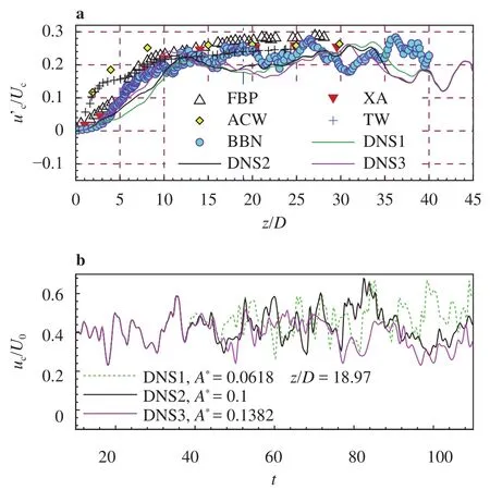
Fig. 4. a The root mean square values (rms) of axial velocity component measured by the local centerline velocity versus the distance to the orifice. b Temporal evolution of centerline velocity at. Note that the vertical dash dot dot line in sunfigure a shows the axial position, and FBP= Fellouah, Ball and Pollard [13], XA= Xu and Antonia [12], ACW= Abdel-Rahman, Chakroun and Fahed [10], TW= Tong and Warhaft [14], BBN= Boersma,Brethouwer and Nieuwstadt [15].
As reported [24, 25], when the swirling-strength of filtered velocity gradient∇is denoted by, the complex eigenvalue of∇is given by, the factor of swirling strength intermittency (FSI) is defined by

To measure jet flow intermittency, we use the mean factor of swirling strength intermittency (MFSI) on the basis of time-circumferential () average, since at any point of turbulent flow,as soon as theFSIis zero, the local flow should be laminar, but if FSI is unity the local flow is fully turbulent. Hence a sub-grid model based onFSIfor large eddy simulation has been developed [24, 25].
To show the MFSI distribution patterns, contours in the-plane are given by Fig. 5(a-c). Carefully identifying indicates the inlet disturbance has some influences on the MFSI distribution pattern. It is seen that there is a more complex structure in the region near the orificein the regionin the area close to lateral boundarythe MFSI is lower. While in most areas of the region further far from the orifice, the MFSI is distributed relative uniformly and in general takes a value in the range from 0.4 to 0.6, except for the near centerline region. Particularly, the jet core displayed by the blue colored cone near the orifice has a relative short length, the cone ends at, 7.8, and 7.2 as0.0618, 0.1 and 0.1382 respectively.
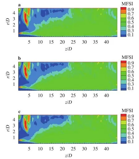
Fig. 5. Contours of the mean factor of swirling strength (MFSI) in the plane, a DNS1,; b DNS2,; c DNS3,
In summary, the DNS results reveal that an intensity increase of inlet flow disturbances can shorten the jet core cone,larger space variations of mean factor of swirling strength intermittency occur in the region near the orifice, but in most areas of the jet flow region that are far from the jet orifice, the mean factor has a value close to 0.5, with an uncertainty of about 0.1.
Acknowledgements
Here we are grateful to the financial support of the National Natural Science Foundation of China (11372303), to the invaluable comments of Professor J.L. Niu at The Hong Kong Polytechnic University.
杂志排行
Theoretical & Applied Mechanics Letters的其它文章
- Continuum percolation of porous media via random packing of overlapping cube-like particles
- Traffic flow and safety analysis
- Air entrainment in a vertical dropshaft with limited air supply
- Intrinsic relationship of vorticity between modes A and B in the wake of a bluff body
- An improved lattice Boltzmann model for high gas and liquid density ratio in composite grids
- A visualized study of interfacial behavior of air–water two-phase flow in a rectangular Venturi channel
