Air entrainment in a vertical dropshaft with limited air supply
2018-11-24QiangDingYiyiMaDavidZhua
Qiang Ding, Yiyi Ma, David Z. Zhua,
a Department of Civil Engineering, Zhejiang University, Hangzhou 310058, China,
b Department of Civil and Environmental Engineering, University of Alberta, Edmonton, T6G 2W2, Canada
Keywords:Air entrainment Air supply Bubble Flow regime Dropshaft
A B S T R A C T Dropshafts are vertical structures widely used in urban drainage systems and buildings for water transportation. In this paper, a physical model study was conducted to investigate the air entrainment in the dropshaft under various flow regimes with and without air ventilation.Observed from the experiments, the air entrainment mechanisms varied with the water flow regimes in the dropshaft. When there was no water plug formed in the dropshaft, air could be supplied directly from downstream. Once the water plug was formed, while without venting, the air was replenished only from downstream intermittently and then in the form of large air bubble traveling upwards to the airspace at the top; while with venting, air was mainly replenished from the dropshaft top and no large air bubble was observed. The experimental results also showed that the amount of entrained air in the dropshaft with venting was greater than that without venting.
Dropshafts are widely used in urban drainage systems as well as buildings to deliver water from a higher elevation to a lower one [1-5]. The dropshaft usually has a drop height of a few dozens of meters and the internal air-water interaction is complex. A good understanding of the air-water interaction in the dropshaft is important to the design and the operation of the system.
The air-water interaction is closely related to the flow regimes in the dropshaft. Chanson [6] defined three flow regimes in rectangular dropshafts according to the position of jet impact.Granata et al. [7, 8] defined subregimes for circular dropshafts by extending Chanson’s classification. Camino et al. [9] divided the flow regimes inside a small scaled dropshaft into free flow, surface roller, plug flow, slug flow and full pipe flow. However, these earlier studies were all conducted under the condition of sufficient venting. Ding and Zhu [10] studied the flow regimes in the dropshaft under the conditions of limited and no air supply.Without air supply, three different regimes of free-flow regime,water-plug regime and choked regime were observed, while only the former two regimes were observed under the limited air supply condition. However, their study only focused on the behavior of the water phase without any consideration of the air phase.
The mechanism of air entrainment by the water flow in a drop structure can be varied, mainly including the impingement of inflow on the wall, the drag of the falling water, and the flow plunging into the bottom pool [6, 7, 11]. For the dropshaft operating with sufficient venting, Camino et al. [12] proposed an empirical relationship between the water flow rate and the entrained air flow rate. Ma et al. [13] developed an equation for predicting the air entrainment in the dropshaft based on the momentum transfer between the air and the water drops. However,there is still lack of study on the air entrainment inside the dropshaft under an insufficient venting condition.
Air bubble is a common form of air entrainment in water. Air bubble distribution in still water has been studied previously [14,15]. The motion of single bubble was well understood and extensive experimental data on shape and terminal velocity were available [14, 16]. In-chain bubbles continually released from a single orifice in stagnant water were investigated [17, 18].However, the air bubble distribution through the falling water inside the dropshaft needs further study.
In this study, the air-water interaction in the dropshaft under various flow regimes was investigated. Experiments were conducted under two ventilation conditions: top-sealed and topopen conditions. In the experiments, the flow regimes and the corresponding air supply processes were recorded and analyzed.The amounts of air transported along the dropshaft under different conditions were estimated.
In this study, a dropshaft system model including an inflow pipe, a circular dropshaft and an outflow pipe was set up for the experiments, as shown in Fig. 1. The diameter of the dropshaft wasDs= 0.15 m and the drop height wasH= 1.75 m (H/Ds> 10).The inflow pipe had a diameter ofDi= 0.10 m and a length of 1.50 m (15Di). The diameter of the outflow pipe was the same as that of the dropshaft and its length was 1.50 m (10Ds). The outflow pipe was connected to the bottom of the dropshaft by a 90°elbow joint with a height of 0.25 m and its end was open to the atmosphere. All the pipes were made of 5 mm thick plexiglass for observing the flow regimes and air transportation inside the model. The top of the dropshaft was 1.00 m above the invert of the inflow pipe and was covered with a plexiglass plate. A soft rubber vent pipe with a valve was installed on the plate. The valve was switched off for the top-sealed condition and switched on for the top-open condition.
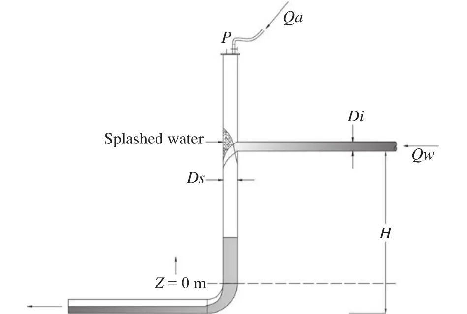
Fig. 1. Schematic diagram of the experimental setup (no air supply from the inflow pipe).
Water was pumped to the inflow pipe and no air entered the dropshaft through the inflow pipe. The water flow rate (Qw) was controlled by a valve installed in the water supply pipeline and was monitored in real time by a magnetic flow meter (KROHNE OPTIFLUX2300C). The magnetic flow meter had a measuring range of 0 ~ 41.67 L/s and an accuracy of 0.2% of the full range(or about 0.08 L/s). In the experiments, the water flow rate started from 1.00 L/s and was increased gradually by an increment of 1 L until the expected flow regime appearing in the dropshaft.
Under different ventilation conditions at the top, the amount of air flow rate entrained into the dropshaft (Qa) was measured by different methods. Under the top-open condition, the amount of air was monitored in real time by a vortex flow meter(TIANKANG LUGB1302-P2) connected to the vent pipe. The vortex flow meter had a measuring range of 1.39 – 11.67 L/s and an accuracy of 2.5% of the full range (or about 0.3 L/s). Under the top-sealed condition, the only entry for the air to the dropshaft was the downstream outflow pipe. The amount of air was estimated from the size and the number of the air bubbles observed in the dropshaft.
The pressure variation in the dropshaft was monitored using a pressure transducer (WESTZH CYB-36SA) placed under the dropshaft cover. The pressure transducer had a range of -20 ~ 50 kPa and an accuracy of 0.1% of the full range (or about 50 Pa). In each experiment, the sampling time of the pressure transducer was set as 120 s.
In the experiments, the flow regime variation, the size and the movements of the air bubbles in the dropshaft were recorded with a high-definition digital video camera (SONY HDRXR350). The video camera had a resolution of 1920 × 1080 pixel and a shooting speed of 25 frames per second. The experiments were conducted at a room temperature of about 20°C.
Under the top-sealed condition, air could only be replenished through the outflow pipe. The mechanism of air supply depended on the flow regime in the dropshaft. At small flow rates,the inflow impacted on the dropshaft wall, with part of the water spreading and falling along the wall while the other rebounding and falling freely in the center of the dropshaft. When the water flow rate was no larger thanQw= 6 L/s, there was an air passage in the dropshaft for ventilation, as shown in Fig. 2(a). It is named as the free-flow regime in Ding and Zhu [10]. In the free-flow regime, the air-water interactions mainly included the followings:(a1) air entrainment by the turbulent water at the impact position, (a2) air drag by the falling water film clinging to the wall and (a3) the free-falling water in the center. In this regime, because that the bottom of the dropshaft was not completely blocked by the water and the outflow pipe was open channel flow, the airspace in the dropshaft was connected with the outside atmosphere and the air in the dropshaft could be fully replenished. Therefore, in the free-flow regime, the reading of the pressure transducer kept to be 0 Pa, which meant that the pressure inside the dropshaft was always the atmospheric pressure.
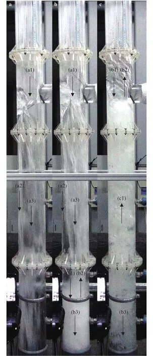
Fig. 2. Air supply process under the top-sealed condition: free-flow regime a Qw = 4 L/s; water-plug regime b Qw = 9 L/s, and c Qw = 12 L/s.
As the water flow rate increased to beQw= 7 ~ 12 L/s, an airwater mixed plug was formed at the bottom of the dropshaft, as shown in Fig. 2(b) and 2(c), which was called water-plug regime in Ding and Zhu [10]. The datumz= 0 m was defined at the junction of the dropshaft and the elbow joint to record the water plug fluctuation and bubble transportation, as illustrated in Fig. 1.When the water flow rate wasQw= 7 ~ 10 L/s, the water plug was unstable, which broke and dropped down quickly after being formed intermittently. When the water plug broke, the water fell directly into the elbow joint. The height of the water plug increased with the water flow rate. It fluctuated within the range ofz= 0 ~ 0.41 m atQw= 7 L/s and increased toz= 0.65 ± 0.20 m atQw= 10 L/s. When the water flow rate wasQw= 11 L/s or larger,the water plug in the dropshaft reached the inlet pipe invert (z=1.50 m) and it became relatively steady.
In the water-plug regime, due to the blockage of the water plug, the air in the dropshaft was transported in the form of small bubbles. The interaction between water and air in the water-plug regime was more complex than that in the free-flow regime. In addition to the processes (a1), (a2), and (a3), it also included: (b1) air entrainment by the turbulent surface of the water plug, (b2) air bubbles moving upward in the water plug which crushed at the surface of the water plug and being released back into the dropshaft, and (b3) air bubbles moving downward in the water plug to the outflow pipe. Notice that atQw= 7 ~ 10 L/s, air still could be replenished intermittently through the downstream outflow pipe when the water plug broke down. Different from the small bubbles formed atQw= 7 ~10 L/s, when the water plug reached the inlet pipe invert (Qw=11~12 L/s), large air bubbles were formed intermittently at the bottom of the water plug, moving upward through the water plug and broke up at the surface of the water plug, which was a process of air supply (c1) to the dropshaft in addition to (b1),(b2), and (b3). According to the experiments, the size of the air bubbles moving upwards through the water plug became significantly smaller as the water flow rate increased.
For the scenario that the water plug reached the inlet pipe invert (Qw= 11~12 L/s), the amount of entrained air can be roughly estimated from the volume of the air bubbles. To simplify the analysis, the large air bubbles traveling in the water plug are approximated as hemisphere atQw= 11 L/s and sphere atQw= 12 L/s. The size of the bubbles can be measured from the images extracted from the videos. AtQw= 11 L/s, the diameter of large air bubble (Da) was about 0.15 m. The bubbles were intermittently formed from the bottom of the water plug at a frequency of about 8 times per minute and rose at a speed of aboutVa= 0.3 m/s until it passed through the water plug and crushed at the water surface, as shown in Fig. 3. Combining these information, it can be estimated that about 7.1 L of air per minute was replenished into the dropshaft in the form of large air bubbles.AtQw= 12 L/s, the large bubble diameter decreased to aboutDa= 0.09 m. The formation of the bubbles was in a frequency of about 4 times per minute and the upward speed was aboutVa=0.3 m/s. In this situation, the rate of the air supply in the form of large bubbles was about 1.5 L/min. Notice that the frequency of large air bubble was corresponding with the pressure fluctuation, as shown in Fig. 4. According to the ideal gas equation, the calculated air volumes were 5.36 and 1.52 L per minute atQw=11 and 12 L/s, respectively, which were close to the measured values.
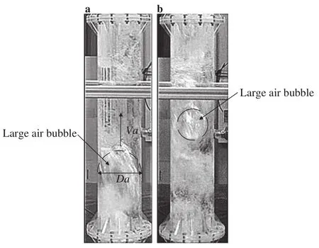
Fig. 3. Large air bubble rising process at a Qw = 11 L/s and b Qw = 12 L/s in water-plug regime.
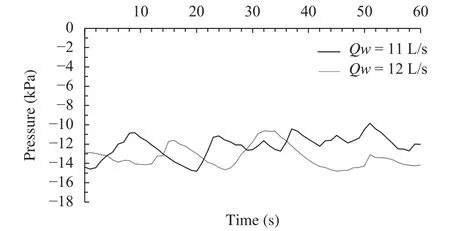
Fig. 4. Pressure fluctuation at Qw = 11 and 12 L/s in water-plug regime.
In the water-plug regime, the air pressure at the top of the dropshaft was negative, which was in balance with the water plug height. Every time the air bubble was released at the surface of the water plug, the balance was broken and the water plug dropped. With the water flow rate increasing, the air in the dropshaft was gradually taken away without timely replenishment, and the height of the water plug gradually increased.
FromQw= 13 L/s on, the water plug completely submerged the inlet and the surface was calm without splashing water. Under this condition, a stable full pipe flow was formed without air bubbles. The flow pattern in the dropshaft kept similar even when the water flow rate increased toQw= 20 L/s. It was considered that the air supply process in the dropshaft had ended.In this situation, the value of the pressure transducer kept at about -1.6 kPa.
Under the top-open condition, air could be replenished into the dropshaft from the top. The free-flow regime of the dropshaft under the top-open condition occurred whenQw= 1 ~ 6 L/s. The flow pattern in this stage was similar to that under the top-sealed condition, and the pressure at the top was also around 0 Pa.
The water-plug regime under the top-open condition also started atQw= 7 L/s. Different from the top-sealed condition,this regime was kept even when the water flow rate increased toQw= 20 L/s. However, compared to the top-sealed condition, the water plug height was lower and the water plug did not fluctuate significantly. Due to the air replenishment from the top, the negative pressure inside the dropshaft was not enough to suck the water plug submerging the inlet. Even if the water flow rate increased to 20 L/s, the water level fluctuated only in the range ofz= 0.46 ± 0.22 m. Therefore, no large air bubble was observed. It could be seen that the ventilation condition of the dropshaft had a significant effect on the flow pattern, which in turn affected the air supply process in the dropshaft.
Under the top-open condition, air could be replenished not only through the outflow pipe but also the air pipe at the top.Therefore, the mechanism of air supply depended on both the status of the water plug and the air pipe at the top. In the freeflow regime, considering that the measuring range of the air flow meter started fromQa= 1.39 L/s, the amount of air replenished through the top of the dropshaft could not be accurately measured. In the water-plug regime, similar to the top-sealed condition, a water plug with a large number of small air bubbles was formed from the bottom of the dropshaft, which was caused by the water plunging into the water plug. As the downstream air supply path was blocked, the air replenishment was mainly through the air pipe at the top. AtQw= 7 L/s, the air flow rate was measured to beQa= 2.68 L/s. As the water flow rate increased,the entrained air flow rate through the air pipe increased significantly. AtQw= 20 L/s, the air flow rate reachedQa= 6.53 L/s.The measured air flow rate in the air pipe and the relative air flow rateQa/Qw, are both shown in Fig. 5. It can be seen that asQwincreased,Qa/Qwshowed a decreasing trend from about 0.4 to 0.3. Compared with the air supply under the top-sealed condition, the amount of air supply through the top air pipe was much larger, which shows a much more significant air entrainment of the dropshaft under the top-open condition. Camino et al. [12]reported that the relative air demand of two dropshafts with relative drop heights ofH/Ds= 19.8 andH/Ds= 31.6 was larger than 10, which were much larger than the value obtained in this study. According to Camino et al. [12], a larger relative drop height would result in a higher relative air demand. In addition to the size differences between these studies, the air supply limit in this study is believed to be the key reason for the much smaller air demand.
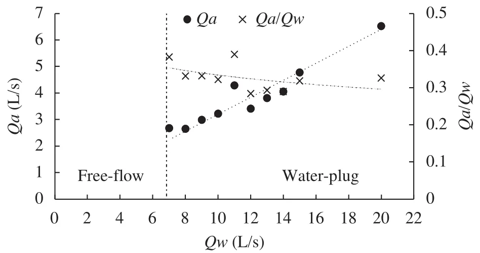
Fig. 5. Air demand Qa and relative air demand Qa/Qw vs. Qw under the top-open condition.
The current work studied the air entrainment in the dropshaft with two different flow regimes of (1) free-flow regime, with the air passage in the dropshaft not blocked, and (2) water-plug regime, with a water plug formed from the bottom of the dropshaft blocking the air supply pass. Different ventilation conditions were also tested in this study. Under the top-sealed condition, the air could only be replenished into the dropshaft by the downstream outflow pipe while under the top-open condition,the air can be supplied from both the outflow pipe and the dropshaft top. According to the experiments, the major air entrainment processes for the free-flow regime included: air entrainment by the turbulent water at the impact position, air drag by the falling water film clinging to the wall and the free-falling water in the center. For the water-plug regime, in addition to those occurring in the free-flow regime, the air entrainment processes also included: air entrainment by the turbulent surface of the water plug and air bubble movement in the water plug. Under the top-sealed condition, the amount of the entrained air in the water-plug regime were estimated to be 5.36 and 1.52 L per minute atQw= 11 and 12 L/s, respectively. Under the top-open condition, the dropshaft was mainly replenished through the top air pipe. The amount of air replenished through the top air pipe under the top-open condition is much greater than that under the top-sealed condition at the same flow rate. Under the topopen condition, although the amount of entrained air increased with the water flow rate, the relative air demand decreased for the blockage of water plug.
Acknowledgements
The authors gratefully acknowledge the financial support from the China Scholarship Council and the Natural Sciences and the Engineering Research Council (NSRC) of Canada. The authors are also thankful for Mr. Guogui Liu of Institute of Municipal Engineering, Zhejiang University for his technical assistance during the experimental work.
杂志排行
Theoretical & Applied Mechanics Letters的其它文章
- Continuum percolation of porous media via random packing of overlapping cube-like particles
- Traffic flow and safety analysis
- Intrinsic relationship of vorticity between modes A and B in the wake of a bluff body
- An improved lattice Boltzmann model for high gas and liquid density ratio in composite grids
- A visualized study of interfacial behavior of air–water two-phase flow in a rectangular Venturi channel
- Inlet flow disturbance effects on direct numerical simulation of incompressible round jet at Reynolds number 2500
