Intrinsic relationship of vorticity between modes A and B in the wake of a bluff body
2018-11-24LinShiWu
L.M. Lin, S.Y. Shi,, Y.X. Wu,b
a Key Laboratory for Mechanics in Fluid Solid Coupling Systems, Institute of Mechanics, Chinese Academy of Sciences, Beijing 100190,China
b School of Engineering Sciences, University of Chinese Academy of Sciences, Beijing 100049, China
Keywords:Mode A Mode B Wake Bluff body Sign law
ABSTRACT The intrinsic physical relationship of vorticity between modes A and B in the three-dimensional wake transition is investigated. Direct numerical simulations for the flow past a square-section cylinder are carried out at Reynolds numbers of 180 and 250, associated with modes A and B,respectively. Based on the analysis of spacial distributions of vorticity in the near wake,characteristics of the vertical vorticity in modes A and B are identified. Moreover, the relationship of three vorticity components with specific signs is summarized into two sign laws, as intrinsic physical relationships between two instability modes. By the theory of vortex-induced vortex, such two sign laws confirm that there are two and only two kinds of vortex-shedding patterns in the near wake, just corresponding to modes A and B. In brief, along the free stream direction, mode A can be described by the parallel shedding vertical vortices with the same sign, while mode B is described by the parallel shedding streamwise vortices with the same sign. Finally, it is found out that the-type vortex is a basic kind of vortex structure in both modes A and B.
Three-dimensional (3-D) wake transition in the wake of a bluff body, as a classical subject in fluid mechanics, has been studied extensively in the literature based on different methodologies, such as physical model experiments, direct numerical simulation (DNS), and linear or nonlinear stability analysis [1-7].Typically for flow past a circular-section cylinder, the first 3-D instability mode, referred as mode A, is appeared with a non-dimensional spanwise wavelengthof approximately 3.96 at a Reynolds number of 190. When the Reynolds number increases up to 230, the second 3-D instability mode, referred as mode B,is observed with. However, there still have some basic unknowns about intrinsic relationship of vorticity in these two modes. It is very important in understanding the evolution of specific vorticity in the wake vortex dynamics, particularly from the point of vorticity sign.
In these two modes, there have distinctly different features of v orticity distributions, i.e. the natural symmetries of modes A and B [2], in the evolving wake dynamics, especially for the formation of streamwise vortices (), as shown in Fig. 1(a), (b) and illustrated in Fig. 1(c), (d), respectively. Mode A comprises streamwise vortices of one sign in a staggered arrangement from one braid region to the next one. While mode B has an in-line arrangement of streamwise vortices of the same sign. Such features are also appeared in the wake transition of a square-section cylinder [7]. However, there still has an unknown problem,i.e., what characteristics of vertical vorticity distributions are, as the first question (Q1). Up to now, the vertical vorticity () is less reported in recent works [5-7]. Moreover, once the distributions of vertical vorticity are known, features of these three components of vorticity in such two modes and relationships of vorticity between them are investigated, as the second and third questions (Q2, Q3).
On the other hand, such two distinct instability modes A and B with different spanwise wavelengths in the near wake of a circular cylinder are not only experimentally measured [2], but also theoretically predicted [1] as shown in Fig. 2, further confirmed in 3-D DNS of wake transition [5, 7]. Besides, a further mode C 3-D instability withhas been proposed by Zhang et al. [8],for the Reynolds number of 170–270, based on the approximate stability analysis. However, such mode is confirmed to be stable in the full Floquet stability analysis [1]. In the numerical simulations and experiments of Zhang et al. [8], it appears that this mode C is the result of forcing on the nominally two-dimensional (2-D) flow, in this case using an interference wire placed close to and parallel to the cylinder axis. Presumably, if one interferes with the 2-D flow field in other ways, one can induce still further 3-D instability wavelengths and modes. Similarly, such mode C,an asynchronous instability different from two synchronous instabilities (i.e., modes A and B), is also qualitatively predicted by applying the Lifschitz–Hameiri theory along special Lagrangian trajectories [4]. It appears, at this point, that the natural wake comprises only the two distinct instabilities yielding modes A and B [2].

Fig. 1. Schematics of symmetry of a mode A and b mode B [2], illustrated by iso-surfaces of streamwise vorticity in c mode A and d mode B through direct numerical simulations for flow past a square cylinder, where dark grey and light yellow denote positive and negative values [7]. Note that the flow is from the left to the right.

Fig. 2. Comparison of non-dimensional instability wavelengthalong with the Reynolds number Re for modes A and B between experiments and Floquet analysis of the wake of a circular cylinder [1].
In a study of the wake instabilities of a square-section cylinder, three wake instability modes, i.e., mode A, mode B, and a quasi-period (QP) mode, have been discovered [9]. Although mode QP is discovered through the Floquet stability analysis with the spanwise wavelengthapproximately 2.6–2.8 and the critical Reynolds number in a range of about 200–220, it is not reported by DNS or experimental studies, consistent with the case of a circular-section cylinder [7].
Therefore, it can be concluded that modes A and B are naturally existed in the 3-D wake transition of a circular- or squaresection cylinder. The fourth question (Q4) is that why only two,not one or three, modes are appeared in the natural wake transition without any interference or perturbation.
In present paper, the main aim is to answer above four questions. By means of numerical simulations of flow past a square cylinder and the theory of vortex-induced vortex (VIVor), proposed in previous work [10], the intrinsic physical relationship of vorticity between modes A and B is investigated.
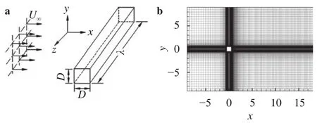
An incompressible flow past the square-section cylinder is taken into account, as shown in Fig. 3(a). Among them, the Cartesian coordinate systemis established, where thex-axis (streamwise) is aligned with the incoming free stream, thez-axis (spanwise) is parallel to the cylinder span, while they-axis(vertical) is normal to theplane. The densityand kinematic viscosityof the fluid are constant.
The continuity and Navier–Stokes equations in dimensionless forms are written out by

Correspondingly the appropriate boundary conditions are employed as follows. As for velocity, the uniform stream with velocityis adopted at the inlet of computational domain. The simple convective outflow,with the convective velocityapplied at the outlet. On both lateral sides of computational domain in thefree slip boundary conditions with velocityare employed. And non-slip boundary conditions with velocityare used on the cylinder surfaces.While for pressure, the compatible pressure boundary conditions, the normal component of momentum equation, are implicitly computed at all boundaries of computational domain. And the reference pressurep∞is zero at the center of inletto avoid the numerical drift.

Fig. 3. a Sketch of flow past a square-section cylinder, and b nondimensional computational domain and mesh distribution.
In spacial discretization, the finite difference method is adopted with the central difference scheme in theplane and the spectral method with Fourier function is applied along the span based on the assumption that the flow is periodic across the span. As for the time scheme for unsteady and convective terms, and so on, the second-order splitting method is adopted[11].
The dimensionless computational domain in theplane is 27×18 (x×y), as shown in Fig. 3(b). And the non-dimensional spanwise computational lengthin Fig. 3(a) is assumed to be one period of 3-D instability modes, i.e., just to capture main features in specific distributions of vorticity in the near wake. The finest grids with non-dimensional spacing about 10-3are clustered near the cylinder and the coarsest grids with spacing about 10-1are distributed away from the cylinder, as shown in Fig. 3(b).
Verification of computational codes is mainly carried out at. And dependence study for mesh and computational domain is referenced in the previous work [12]. For example, the Strouhal number, defined aswhereis the vortexshedding frequency, is obtained to be 0.149, agreed well with 0.146 in experiments [3].
Computations are performed firstly for the first instability mode A atwith, and then for the second instability mode B atwith[3]. Total computational Fourier modes for both modes A and B are 32 and 16, respectively [1]. The-th wavenumberis defined asin spectral space. In Eq. (2), the spanwise viscous item,can be expressed by a sum of Fourier modes,spanwise Four-Therefore, viscous dissipation becomes important at wavenumbersAnd at wavenumbersthe momentum equations are dominated by viscous forces [1]. These high-wavenumber modes contribute little to the dynamics of the flow at large scales because their energy is rapidly dissipated by viscosity. For an adequate description of the dynamics in a system with a given spanwise dimensionwe only need a finite set ofFourier modes to cover the range of scales from(the mean flow) toHereby, we just investigate the 3-D flow dynamics with spanwise periodicity at the smallest periodic resolutionin present paper, considering to eliminate the aliasing error in computing non-linear convective terms. The moments for modes A and B are chosen after the wake flow is steady and periodic with periodical variations of drag and lift coefficients,and, along the time. According to the features of three components of vorticity distributed in the near wake, the intrinsic relationship between modes A and B is presented and discussed, from the point of vorticity and its sign.
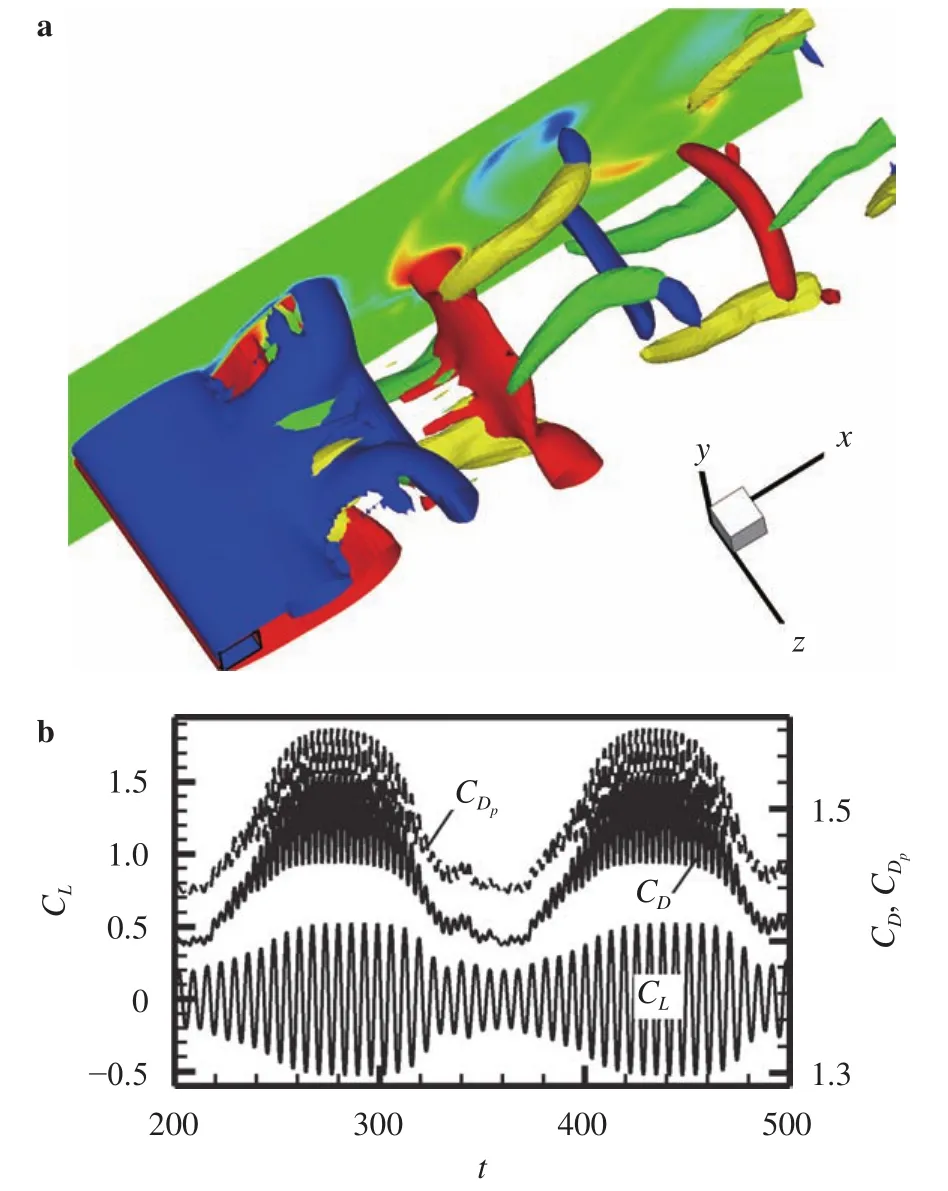
As for mode A as shown in Fig. 4(a), the wake can be described by the-type vortices alternatively shed from the upper and lower shear layers. The moment associated to the appearance of 3-D vortex-shedding pattern is corresponding to reduction of fluid forces, as shown in Fig. 4(b). In such-type vortex,the head line, "—", denotes the spanwise vortex alternatively shed from the upper or lower shear layer. While two legs, "||", denote that streamwise and/or vertical vortex pairs with opposite signs are also alternatively shed with such spanwise vortex and thus stretched or elongated into the upstream vortex braid region by the upstream spanwise vortex of opposite sign, consistent with the description in Ref. [2].

Fig. 4. a Iso-surfaces of (yellow/green) and (red/blue) describing mode A in the near wake of the square-section cylinder at and with, and b time histories of drag coefficient , its pressure contribution and lift coefficient , where the background is the contour of at.Note the square cylinder is shown by the wire frame.
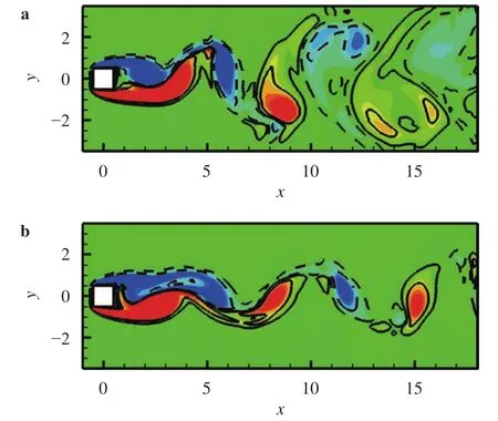
Now let us examine the sign of streamwise and vertical components of vorticity in such-type vortex. As a typical example,the flow in section of
is concerned. As shown in Fig. 5(a), the streamwise vorticity with positive and negative signs is firstly concentrated in the shear layers. Then the streamwise vortices are formed and alternatively shed from the upper and lower shear layers, respectively. However, as shown in Fig. 5(b), the vertical vorticity mainly with positive sign is initially accumulated in and then alternatively shed from both shear layers. Therefore, such characteristics in the near wake can be simply denoted by the following vorticity signs:dicates that the streamwise vortices are shed in a staggered manner with opposite signs between two neighboring vortex braid regions along not only the streamwise direction but also the spanwise direction, while the vertical vortices are shed in a staggered arrangement with opposite signs only across the span but parallel to each other with the same sign along the stream-wise direction.

Fig. 5. Contours of a and b at in the case of Fig. 4,where red and blue colors, as well as solid and dashed lines in contours of, denote positive and negative values, respectively.
Or from the point of a single-type vortex shed in the near wake, we have:in the upper-type vortex withwhilein the lower-type vortex with +|ωz|.
Moreover, as a result of such specific distributions of streamwise and vertical vorticities, the original 2-D spanwise vortices are disturbed wavily across the span, as well as the shear layers and wake width. According to the VIVor theory [10], the induced spanwise vorticity would be positive and negative in the upper shear layer atand, respectively, but negative and positive in the lower shear layer atand,respectively. This results in the value of total spanwise vorticitydecreased atbut increased atfor both shear layers. Such variation of spanwise vorticity is associated with the vorticity diffusion at, as shown in Fig. 6(a), and the vorticity concentration near the wake center plane atas shown in Fig. 6(b).
Interestingly, the wake for mode B instability can also be described mainly by the-type vortices alternatively shed but with smaller spanwise wavelength and scattered spanwise vortices of opposite sign, as shown in Fig. 7(a). In the whole computational time, vortex shedding in mode B is exactly periodical just with constant amplitudes of fluid forces, as shown in Fig. 7(b), obviously different from those in mode A.
Through careful examination of streamwise and vertical components of vorticity in the near wake and comparison with those in mode A, we find out some similarity between them. As an example at, the streamwise vorticity with a negative sign is concentrated in both shear layers and then alternatively shed, as shown in Fig. 8(a). But as shown in Fig. 8(b), the vertical vorticity with negative and positive signs is firstly accumulated in the upper and lower shear layers, respectively, and then alternatively shed with the negative and positive spanwise vortices, respectively. Resultantly, this feature can be summarized by the following relationship:Different from those in mode A, it shows that the streamwise vortices are shed in a staggered manner with opposite signs only along the span-wise direction but in the in-line arrangement or parallel to each other with the same sign between two neighboring vortex braid regions, while the vertical vortices are shed in a staggered arrangement with opposite signs between two neighboring vortex braid regions along not only the streamwise direction but also the spanwise direction.

Fig. 6. Contours of at a and b in the case of Fig. 4,where red and blue colors, as well as solid and dashed lines, denote positive and negative values, respectively.

Fig. 7. a Iso-surfaces of (yellow/green) and(red/blue) describing mode B in the near wake of the square-section cylinder at and with, and b time histories of drag coefficient , its pressure contribution and lift coefficient.

Fig. 8. Contours of a and b at in the case of Fig. 7,where red and blue colors, as well as solid and dashed lines in contours of, denote positive and negative values, respectively.
Furthermore, we have the following relationship too:in the upper-type vortex withwhilein the lower-type vortex withIn addition, we define thevortex as the upper-type vortex (at dimensionless spanwise wavelengthwith sign combinations ofatatjust as shown in Fig. 4, and thevortex as the lower-type vortex with sign combinations ofandat. Mode A thus can be described by thevortices alternatively shed in phase across the span, while mode B is described by thevortices alternatively shed out of phase across the span. Furthermore, it can be seen that a kind of symmetry about the time in half vortex-shedding period and the wake center planeis actually existed between thevortices [1]. This further confirms that the-type vortex, thevortex, is a fundamental vortex structure in both modes A and B in the wake transition of a bluff body.
Now let us see the effect of those special distributions of streamwise and vertical components of vorticity on the spanwise vorticies, obviously different from mode A, as shown in Fig.9. Based on the analysis of VIVor theory, the negative and positive streamwise vortices in the upper shear layer across the span induce the induced spanwise vorticity with a positive sign atand a negative sign atrespectively. On the other hand, the streamwise vortices with same opposite signs in the lower shear layer have an exactly equivalent effect on the induced spanwise vorticity across the span. The coupled effects of these streamwise vortices in both the upper and lower shear layers result in the negative spanwise vorticity weakened and diffused outwards and the positive spanwise vorticity intensified and concentrated near the wake center plane at, as shown in Fig. 9(a), and exactly opposite to those atin Fig. 9(b).

Fig. 9. Contours of at a and b in the case of Fig. 7, where red and blue colors, as well as solid and dashed lines,denote positive and negative values, respectively.
From above analysis, the intrinsic relationship of vorticity between modes A and B is presented and discussed. Typically,two sign laws in such vorticity relationship are summarized. The sign for combination ofand, is positive in the upper shear layer or the upper-type vortex but negative in the lower shear layer or the lower-type vortex, as the first sign law,which is independent of wavy spanwise vortices. However, the sign for combination of all three components of vorticity, i.e., is always negative for both the upper and lower shear layers ortype vortices, as the second sign law, regardless ofandstretched into upstream vortex braids withof opposite sign. Howbeit, these summarized sign laws in modes A and B have not removed the possibility of other 3-D instability mode yet.
Recently, the theory of vortex-induced vortex [10] is proposed, from the point of investigating the specific sign of vorticity distributed in the wake of a bluff body. Two sign laws in the shear layers and near wake (), as intrinsic physical relationships between different components of vorticity, are obtained as follows:

where sgn is the sign function, except certain positions where. Here region ofdenotes the lower shear layer or spanwise vortex with a positive sign, while region ofdenotes the upper shear layer or spanwise vortex with a negative sign. Present two sign laws are exactly consistent with above two summarized sign laws in the near wake,associated with the formation of-type vortices.
Therefore, according to the VIVor theory and two sign laws, it is theoretically confirmed that two and only two kinds of specific sign combinations of three vorticity components are existed in region of, just associated with modes A and B, respectively, in natural 3-D wake transition of a bluff body. Or from the point of specific voriticy in the near wake, the staggered arrangement of streamwise or vertical component of vorticity with opposite signs along the streamwise or spanwise direction is taken as a basic feature between two neighboring vortex braids associated with alternatively shedding spanwise vortices with opposite signs. Thus the key role is the vertical vortices in mode A or the streamwise vortices in mode B, parallel to each other with the same sign along the streamwise direction between two neighboring vortex braids.
In present paper, in order to find out the intrinsic relationship of vorticity in two wake instability modes, modes A and B,the flow past the square-section cylinder is numerically simulated at Reynolds numbers of 180 and 250. Through analysis of spacial distributions of vorticity and its sign in the near wake,four questions are answered as follows:
(Q1) The vertical vorticity has its own features different in modes A and B. In mode A, it is parallel to each other with the same sign along the streamwise direction between two neighboring vortex braid regions. However in mode B, it is in a staggered manner with opposite signs along the streamwise and spanwise directions between such braid regions.
(Q2) There are special distributions of three components of vorticity with specific signs in modes A and B. In mode A, it isandBut in mode B, it becomesand
(Q3) Two sign laws are summarized based on the answer of Q2 and further verified by the VIVor theory in region ofThe first sign law presents the sign combination ofpositive in the upper shear layer or thevortex but negative in the lower shear layer or thevortex. The second sign law indicates the sign combination ofalways negative in both the upper and lower shear layers or-type vortices.
(Q4) In natural wake transition of a bluff body, it is confirmed that there are two and only two 3-D vortex-shedding patterns by two sign laws predicted by the VIVor theory in region of,just associated with modes A and B with their specific vorticity distributions.
Consequently, modes A and B have the following simplified features:
(1) Mode A can be described by the shedding vertical vortices parallel to each other with the same sign along the streamwise direction between two neighboring vortex braids. While mode B is illustrated by the shedding streamwise vortices parallel to each other with the same sign along the streamwise direction between two braids.
(2) Mode A can also be described by thevortices alternatively shed in phase across the span. While mode B is demonstrated by thevortices alternatively shed out of phase across the span. Therefore the-type vortex is a basic vortex structure in the 3-D wake transition of a bluff body.
Acknowledgements
This work was financially supported by the Strategic Priority Research Program of the Chinese Academy of Science (Grant XDB22030101).
杂志排行
Theoretical & Applied Mechanics Letters的其它文章
- Continuum percolation of porous media via random packing of overlapping cube-like particles
- Traffic flow and safety analysis
- Air entrainment in a vertical dropshaft with limited air supply
- An improved lattice Boltzmann model for high gas and liquid density ratio in composite grids
- A visualized study of interfacial behavior of air–water two-phase flow in a rectangular Venturi channel
- Inlet flow disturbance effects on direct numerical simulation of incompressible round jet at Reynolds number 2500
