A visualized study of interfacial behavior of air–water two-phase flow in a rectangular Venturi channel
2018-11-24JiangHuangLichengSunMinDuZhengyuMoLiangZhao
Jiang Huang, Licheng Sun, Min Du, Zhengyu Mo, Liang Zhao
State Key Laboratory of Hydraulics and Mountain River Engineering, College of Water Resource & Hydropower, Sichuan University,Chengdu 610065, China
Keywords:Venturi channel Reentrant jet flow process Interfacial behavior Bubble breakup Diverging angle
ABSTRACTA visualized investigation was carried out on the effect of the diverging angle on the bubble motion and interfacial behavior in a Venturi-type bubble generator. It was found two or three large vortexes formed in the diverging section, resulting in strong reentrant jet flow in the front of the bubbles or slugs rushing out of the throat. The jet flow in return bumps into the ongoing bubbles or slugs, leading to strong interaction between the gas and liquid phases. The diverging angle has significant influence on the reentrant flow process and the performance of the bubble generator as well. Increasing the diverging angle results in the reentrant flow moving further forward to the upstream and intensifies the interaction between the two phases. As a consequence, the breakup or collapse of bubbles becomes more violent, whereby finer bubbles are generated. As such, the reentrant flow strongly links to the performance of the Venturi channel taken as a bubble generator, and that a moderate increase in the diverging angle can improve its performance without additional increase in flow resistance like that by increasing liquid flow rate.
Venturi structure equipments are widely utilized in various engineering and research fields, such as flow measurement[1, 2], off-gas removal system [3, 4], scrubber [5, 6], chemical or biochemical reaction [7], etc. Besides, as a simple and robust design, Venturi channel has been employed as bubble generators [8–11]. With injecting gas into a high-speed liquid flow in a Venturi channel, the gas experiences a complex transportation process and ends up of being broken up into a large number of tiny bubbles in the diverging section.
Venturi-type bubble generators have been applied to water purification, froth flotation, and chemical reaction, etc., due to their high efficiency in producing bubbles. They receive increasingly attention on their performance [12, 13], but less on the mechanism inducing bubble breakup. Early theory relevant to the breakup of bubbles or droplets in turbulent flows was independently proposed by Kolmogorov [14] and Hinze [15], respectively. Hinze [15] proposed that bubble breakup occurred through interactions of a bubble with turbulent eddies of a size approximating the bubble diameter. The bubble would be collapsed into many tiny bubbles once the maximum hydrodynamic force in the liquid exceeded the surface tension force.After that, more models were put forward with more factors taken into consideration like the collision frequency, breakup probability, breakup rate and the daughter size distribution, etc.Luo and Svendsen [16] developed a theoretical model for predicting the rate of bubble breakup in turbulent dispersions.When bubbles are hit by turbulent eddies, the probability for bubble breakup is determined by the energy contained in the eddies and the minimum energy required for increasing the surface area after breakup of the bubbles. In view of the mechanism of exchanging energy between turbulent eddy and interfacial area of a bubble, Yao and Morel [17] pointed out that the bubble breakup could also occur under the condition ofWe<Wecr, they took into account the resonance of bubble oscillations with turbulent eddies in a new model. Lehr et al. [18]assumed that the force between the eddies and bubble collisions dominated the bubble breakup. It would occur immediately once the inertial force of the colliding eddy exceeded the surface tension. A breakup kernel function was derived to calculate the breakup rate on the basis of the frequency of arriving eddies onto the bubble and the breakup probability arising from the collisions.
Experimental investigations have also been conducted to illustrate the mechanism dominating the bubble breakup process [19–21]. For the case of the Venturi-type bubble generator,more work focused on statistical results regarding bubble size and distribution [3, 22–26]. Gabbard [3] proved that the averaged bubble diameter was strongly linked to surface tension and Reynolds number and presented a dimensionless correlation to predict the bubble diameter against experimental results. Similar relationship was also found by Yin et al. [23] and Sun et al.[25]. Gordiychuk et al. [24] carried out an investigation on the factors influencing the size distribution of bubbles in a Venturitype bubble generator, such as air/water Reynolds number and volume fraction. They concluded that the bubble size was inversely proportional to the water flow rate and got increased with the increase in the volume fraction. Li et al. [26] focused on the effect of the geometrical parameters of a Venturi channel on the size distribution of the generated bubbles. They proved that increasing the diverging angle resulted in smaller bubbles being produced under the same flow condition.
In a high-speed liquid flow field inside a Venturi-type bubble generator, a relatively large bubble always experiences expansion, deformation and final breakup in the generator. Rapid pressure recovery from the kinetic energy has an enormous effect on bubble breakup in the gradually diverging section[22, 27–30]. In order to clarify the bubble breakup phenomenon in a Venturi channel, Fujiwara et al. [22] designed a microbubble generator available for a wide range of void fraction.They found that it was easier for the liquid to reach sonic speed in the throat due to a slower sonic speed in gas–liquid flow than that in single-phase flow of the gas or liquid. Local pressure rose suddenly at a certain position in the diverging section, where a steady shock wave appeared. It suggested that the bubble breakup was caused by the strong shock-type pressure recovery in venture channel. Uesawa et al. [28] presented the fluctuation of void fraction quantitatively in a Venturi tube by measuring the electrical conductivity of the fluids. Transient void fraction could be obtained from the change of the electrical resistance arising from varying containment of the gas component in the mixture.It was demonstrated that void fraction experienced dramatic variation before and after bubble collapse. Li et al. [31] focused on the mechanism of bubble breakup in a micro-scale Venturi.They found that shearing-off process and turbulence fluctuation were the dominating mechanisms for inducing bubble breakup.
Efforts were extended in research to explore the performance of a Venturi-type bubble generator as well as the mechanism dominating the bubble breakup. Fujiwara et al. [22] and Nomura et al. [27] observed a liquid jet behind a bubble in the entrance of the diverging section, which almost penetrated through the entire bubble and broke the bubble into several pieces. While our previous work [25, 32, 33] indicated a strong deceleration of bubbles within a short distance once the bubbles entered the diverging part of the Venturi channel. It was believed that this played a paramount role in inducing bubble collapse. Current work focuses on the interfacial behaviors in the same Venturi channels with our previous work [25, 32, 33]. A larger void fraction was extended in the experiments to illustrate the interfacial behavior and obtain detailed information involved, which will help to reveal the mechanism dominating the intensified bubble fragmentation process in a Venturi-type bubble generator.
Figure 1 presents the dimensions of the Venturi-type bubble generator for test as well as the schematic of the experimental system. The bubble generator is actually a rectangular Venturi channel, including three sections: a convergent entrance, a throat, and a gradually divergent outlet. It was fabricated with transparent perspex for a better observation. A small hole of 1 mm in diameter was opened in the throat to feed air into the stream. For measuring the local pressures, three pressure taps were opened at the inlet, throat, and outlet of the Venturi channel to connect the pressure sensors.
The experimental setup mainly consists of a water supply loop and a gas supply line. Air supplied by an air compressor is stored in a gas tank beforehand, thus it can provide the air with a specified pressure to the experimental setup. Air is injected into the throat through the air feeding hole and mixed with the main flow, as schematically indicated in Fig. 1. After flowing out of the test section, air is released into the atmosphere and water goes back to the water tank. All the experiments were carried out at room temperature and atmospheric pressure. The water and air flow rates covered the range of 1.9–9.0 m3/h and 0.07–8.25 L/min, and were measured by two mass flowmeters with accuracy of 0.1% and 1.0%, respectively. A high speed camera (FASTCAM Mini UX100) is mounted above the Venturi-type bubble generator to record the bubble motion and the interfacial behavior of air–water flow. The shutter speed of the camera was set to 10000–20000 fps. A cold light (XD-301, SangNond) is placed under the test section as a supplementary lighting.
Figure 2 presents the complex interfacial behavior in the diverging section with the liquid flow rate covering the range of 1.91–5.40 m3/h, corresponding to liquid only Reynolds number of 3.0×10⁴–8.6×10⁴in the throat. With increasing the liquid flow rate, more fierce interaction between the two phases could be observed, particularly for the cases with high flow rates, which even induced violent collapse of air bubbles or slugs. This is the basic feature or the key reason for a Venturi-type bubble gener-ator owning such excellent performance in producing fine bubbles.
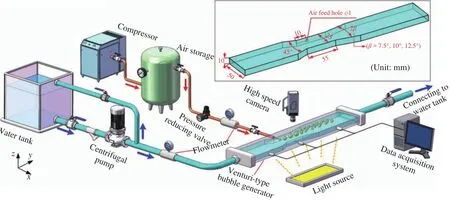
Fig. 1. Dimensions of the Venturi-type bubble generator for test as well as the schematic of the experimental system.
Detailed information of the transportation of air bubbles in the channel is illustrated in Fig. 2 as well. After rushing out of the throat with the liquid, the air bubbles or slugs were rapidly decelerated in the diverging section, as clearly shown in Fig. 2(a)for the case with the liquid flow rate ofQL= 1.91 m3/h. The deceleration gave rise to bubbles stacking in the diverging section till they coalesced to form a larger one. Increasing the liquid flow rate accelerated the bubble coalescence process, as can be seen in Fig. 2(b), and even before entering the diverging section,bubble coalescence has taken place. At the flow rate ofQL= 2.41 m3/h, coalesced bubble was broken up in the region around 45–65 mm away from the entrance of the diverging section. It can be clearly seen by comparing Fig. 2(c) and (d), that increasing flow rate also incurred earlier collapse of the air slugs. While for the case of a higher gas flow rate, the breakup or collapse of a gas slug might hardly occur, as indicated in Fig. 2(e) (QG= 2.41 L/min). The gas slug kept expanding in the diverging section till it nearly occupied the main part the channel. Large amplitude wave were present on the interface, and continuous breakup of the waves formed a source of fine bubble entrainment in the main stream.
A strong reentrant jet flow of the liquid in the diverging section could be easily observed, which is believed to play a paramount role in the collapse of the gas slug. Figure 3 indicates the reentrant jet flow process at the liquid flow rate ofQL= 3.09 m3/h by observing the movement of the interface. The leading front velocity of the interface is basically the reentrant flow velocity on the premise that there is on relative velocity between the liquid and the air near the interface. Several representative points on the profiles of the leading front were marked with asterisks as shown in Fig. 3(b). By measuring the movement distance of these representative points, their velocities can be obtained.Then the average value of the velocities was then used to represent the reentrant flow velocity and interfacial velocity. Collision of the reentrant jet flow on the oncoming gas slug triggered strong disturbance across the interface. A leading front of the reentrant jet flow can be clearly seen in Fig. 3(a), which is marked by an orange line. It was decelerated during the reentrant jet flow from initial velocity of around 1.0 m/s to nearly standstill in a very short period of time about dozens of milliseconds, as given in Fig. 3(b) with respect to transient mean velocity of the leading front. The magnitude of the deceleration of the leading front is expected to be as high as 100 m/s2during the reentrant flow process. Furthermore, the leading front varied from a flat profile to a triangular one during this process, very much like a pointed liquid slug penetrating into the gas slug, resulting in stronger interaction between the gas and liquid phases.This gave rise to intense surface waves across the interface as shown in Fig. 3(a), and led to continuous collapse of the head of the gas slug. Figure 3(c) presents the variation in velocity of the leading front of the reentrant flow, its trend of deceleration could be clearly observed. For the case of the liquid flow rate of 3.09 m3/h and the diverging angle of 10°, the averaged velocity of the leading front was decreased from around 1.0 m/s to nearly stop within 35 ms. The reentrant jet flow induced strong waves on the part of the interface it contacted with, making this part become more unstable and easily to be stripped off from the gas slug.Figure 4 presents the reentrant jet flow process under different flow rates and diverging angles condition. Similar process could be observed in all the three Venturi channels under different flow condition. It further proves that reentrant jet flow is a common process and closely related to the bubble breakup or collapse.
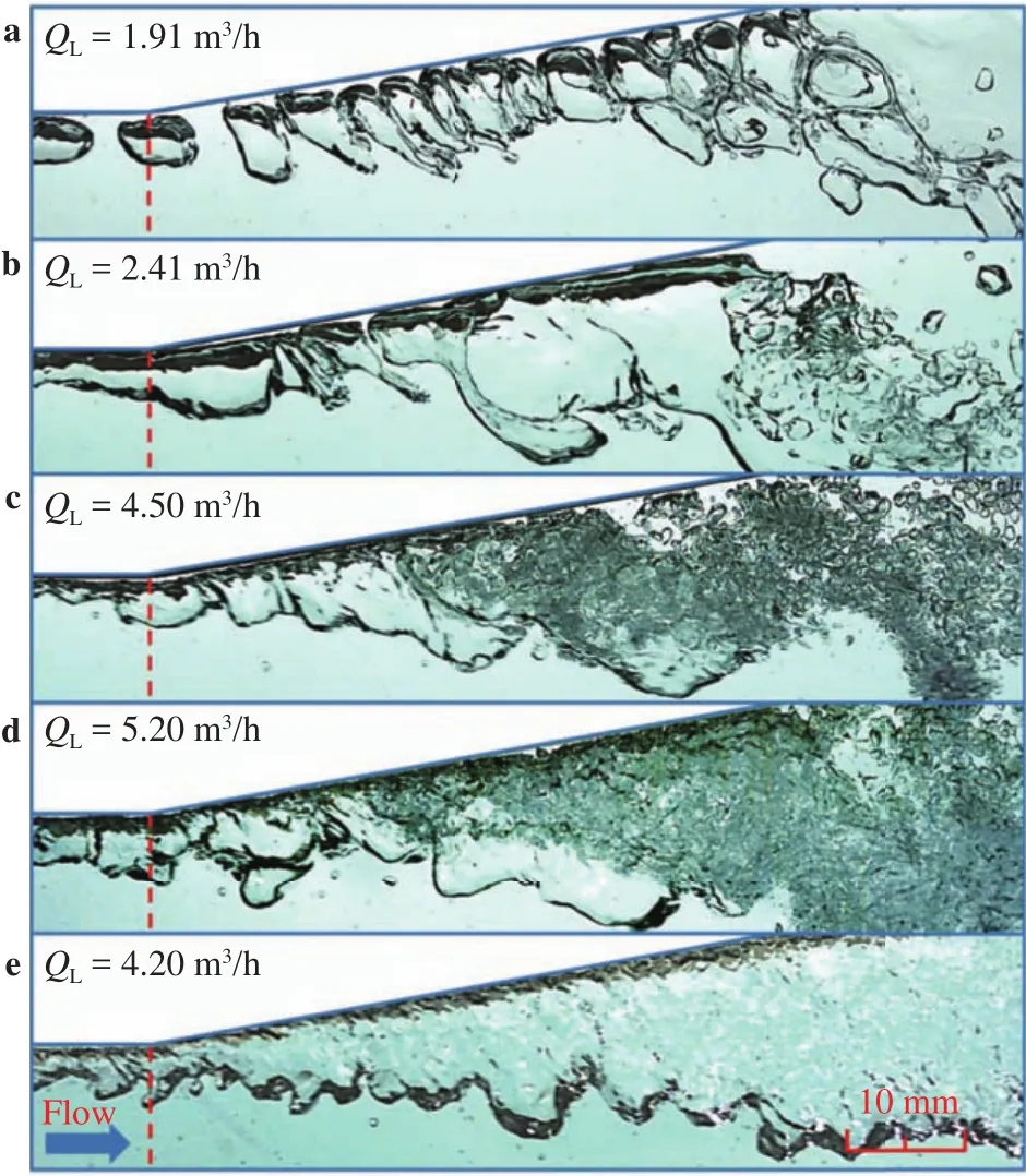
Fig. 2. Interfacial behavior in the diverging section at different liquid rates (diverging angle β=10°).
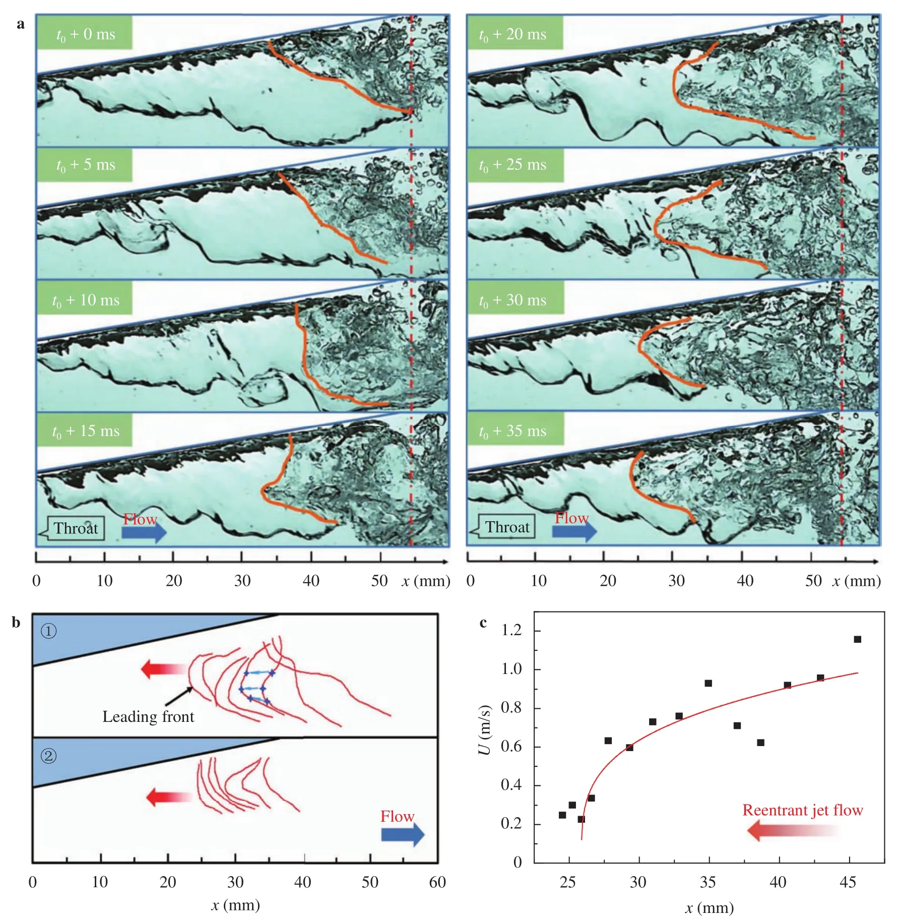
Fig. 3. Reentrant jet flow process and the velocity of the leading front of the reentrant jet flow in the diverging section (QL = 3.09 m3/h, β = 10°).a Reentrant jet flow process, b profiles of the leading front, c mean velocity of the leading front.
The diverging geometry creates strong reentrant jet flow of the liquid, without which it would be difficult to induce bubble collapse. Figure 5 presents the effect of the diverging angel on the reentrant jet flow process. Three different diverging angles of 7.5°, 10°, and 12.5° were compared. Increasing the diverging angle led to the reentrant jet flow region moving forward and closer to the entrance of the diverging section, although there was no obvious difference in reentrant jet flow velocity among the three cases. With the reentrant jet flow moving to upstream,larger part of the gas slug was influenced. Profiles of the leading front of the reentrant jet flow at different instants were extracted and overlapped on one picture, as shown in Fig. 5(d), corresponding average velocities of the leading front were also presented. Clearly, the diverging angle had little effect on the reentrant jet flow velocity and profiles of the leading front, but significantly influenced its occurrence position. In fact, the striking of the reentrant jet flow on the gas slug head lasted only a very short period about tens of milliseconds before the formation of the next one. This will certainly induce very much stronger interaction between the gas and liquid, with which is incomparable for that in conventional channels.
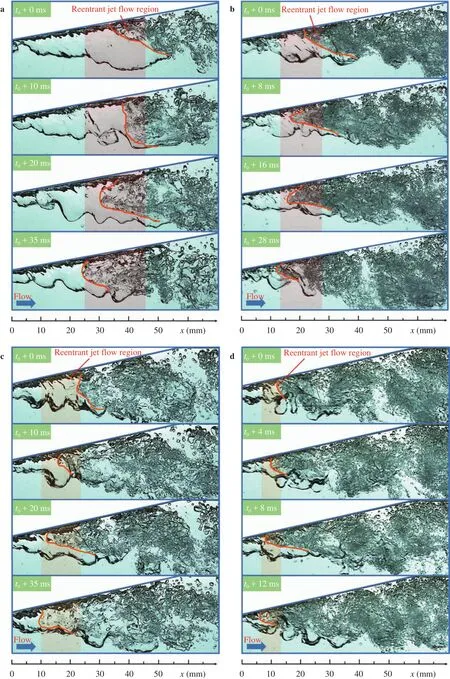
Fig. 4. Reentrant jet flow processes with different diverging angles and liquid flow rates.a β = 10°,QL= 3.09 m3/h,b β = 10°,QL= 4.50 m3/h,c β = 12.5°,QL= 3.10 m3/h,d β = 12.5°,QL= 4.60 m3/h.
Figure 6 presents the effect of the liquid flow rate on the reentrant jet flow process. Increasing the liquid flow rate led to the reentrant jet flow region further moving forward, and a more intensified gas slug collapse was observed. The jet flow plunged deep into the head of the gas slug in shorter time, thereby a much stronger collapse process was resulted. The profiles of the leading front at different positions were extracted and presented in an image, as given in Fig. 6(c), and the averaged reentrant jet flow velocity of the front were given in Fig. 6(d). Very clearly that increasing the liquid velocity induced reentrant jet flow moving further forward and led to a larger magnitude of deceleration of the gas slug. While compared with that of the diverging angle,the liquid flow rate has a smaller effect on the front position of the reentrant flow. From this perspective, increasing the diverging angle is a more efficient way in enhancing the interaction between the liquid and gas.
As mentioned above, reentrant jet flow induces stronger interaction between the gas and liquid, this also gives rise to subsequent separation of the influenced part from the gas slug. Figure 7 presents the gas slug collapse process at the liquid flow rate ofQL= 3.05 m3/h. With the reentrant jet flow moving forward,small bubbles are being sheared off from the gas slug. Once the leading front of the reentrant jet flow reaches the crest of the wavy interface edge, the main part of the gas slug behind the leading front was stripped off and was then collapsed completely by the vortex in the wake of the reentrant flow. This illustrates that the reentrant flow is the prerequisite of bubble breakup or collapse. It is the reentrant flow induced by the diverging structure that intensifies the interaction between the liquid and gas slug, without which it would be difficult for the collapse process to be incurred only by high speed liquid flow.
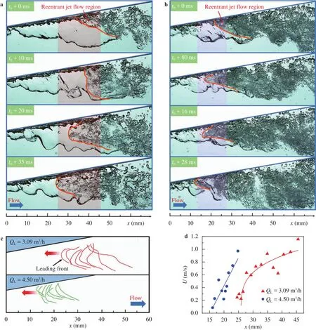
Fig. 6. Reentrant jet flow process at different liquid flow rates (β=10°). a QL = 3.09 m3/h, b QL = 4.50 m3/h, c history profiles of the leading front,d mean velocity of the interface.
Another point which should be noted is that there exists an almost stagnation region in the front the gas slug, as shown in Fig. 7. The region functions as an obstruction to the gas slug,hindering it from moving forward and making the slug head to detach from the wall. This consequently forces the entire slug head to face the most intensive region and thereby it would be impossible for the gas slug escaping from the direct hit of the reentrant flow.
As indicated in Fig. 7, once the leading front of the reentrant jet flow reached the edge of the wavy interface, the head of the gas slug started to separate from the slug, and was then collapsed by the vortex in the front of the gas slug. This process proved that the strike of the reentrant jet flow on the gas slug and the vortex played key roles in collapsing the gas slug. The former makes a much stronger penetration of the liquid into the gas slug, resulting in the head of the gas slug becoming unstable; following the vortex help separate the unstable part from the slug,and collapse it into fine bubbles.
The effect of the diverging angle on the gas slug collapse is shown in Fig. 8. A larger diverging angle led to deeper penetration of the liquid into the gas slug, thereby a larger part was separated from the gas slug, and a more intensive collapse process was resulted.
Turbulence induced by the high speed liquid flow is in the first place for bubble breakup or collapse. For a Venturi channel,the diverging section significantly modifies the flow structure compared with that in a conventional channel at the same flow rate. Several large eddies creates strong reentrant flow, forming a strong hit on the gas slug. With the increase of the liquid flow rate, the reentrant jet flow moved further to the upstream, and larger part were separated from the gas slug. Much finer bubbles were generated, as indicated in Fig. 9. Situations of three liquid flow rates, 2.41, 3.09, and 4.50 m3/h, were compared.
Previously discussions indicated that the diverging angle had significant effects on gas slug collapse, a larger diverging angle could induce more intensified collapse of gas slugs. To explore the reason of it, an overall presentation of the flow structure in the diverging section is shown in Fig. 10. Several large vortexes could be identified along the flow and are marked with red arrows, which are formed due to the diverging structure of the Venturi channel. The vortexes kept rotating counterclockwise,resulting in reverse flow to the fluid near the wall. The reverse flow transfers energy from the downstream to upstream and finally gives rise to strong reentrant flow near the entrance of the diverging section. Actually, vortex in the downstream can barely break up or collapse the bubbles, only the nearest one to the gas slug head could induce bubble collapse. Bubbles in the downstream were generated from slug collapse in the upstream and can not be further broken up in the downstream.
A further observation of the flow process indicates that for the case of larger divergent angle, the vortex around the same position was larger than that of a smaller diverging angle, as illustrated in Fig. 10. Although, these vortexes cannot further break up the bubbles around them, they were larger in size and had a faster rotation velocity, thereby they transferred more energy to the fluid round them. Consequently, the fluid near the wall in the diverging section obtained higher velocity to flow backward. The energy from the vortexes in the downstream was then transferred to the upstream, finally making the reentrant jet flow and the vortex near the gas slug head own larger energy,and leading to more intensified bubble collapse therein.
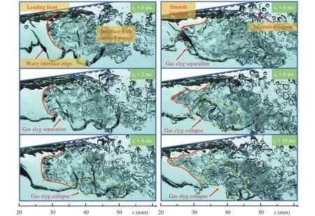
Fig. 7. Collapse process of a gas slug (QL = 3.05 m3/h).
Effects of the diverging angle on bubble motion and interfacial behavior was investigated to further understand the mechanism dominating bubble breakup or collapse in a Venturi-type
bubble generator. Conclusions are summarized as follows:
(1) Strong reentrant jet flow process exists in the diverging section, which plays a key role in decelerating a bubble or a slug.The strike of the reentrant jet flow on the bubble or slug induces strong interaction between the gas and liquid phases.
(2) The diverging angle has significant effect on the reentrant jet flow process. A larger angle leads to the reentrant flow further plunging into the gas slug, resulting more intensified bubble breakup or collapse process.
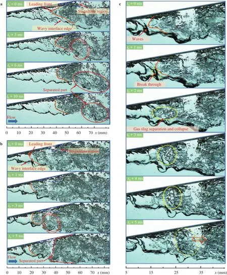
Fig. 8. Collapse processes of the gas slug in the Venturi channel with different diverging angles. a β = 10°, QL = 3.09 m3/h, b β = 12.5°,QL = 3.10 m3/h, c β = 12.5°, QL = 3.10 m3/h
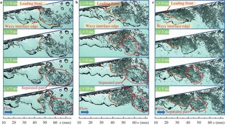
Fig. 9. Effect of the liquid flow rate on gas slug collapse. a QL = 2.41 m3/h, b QL = 3.09 m3/h, c QL = 4.50 m3/h.
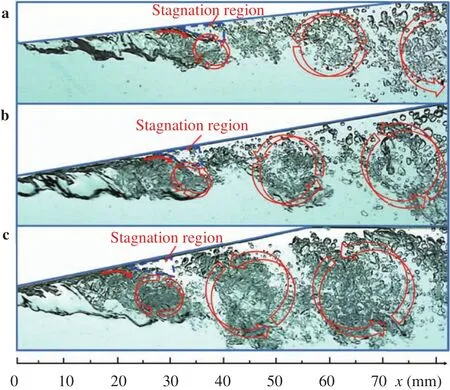
Fig. 10. Overall view of flow structures in the diverging section(QL=3.10 m3/h).
(3) A moderate increase in the diverging angle is an efficient way for improving the performance of a Venturi-type bubble generator without additional power consumption.
Acknowledgements
This work was supported by the National Natural Science Foundation of China (Grants 51709191, 51606130, and 51506099).
杂志排行
Theoretical & Applied Mechanics Letters的其它文章
- Continuum percolation of porous media via random packing of overlapping cube-like particles
- Traffic flow and safety analysis
- Air entrainment in a vertical dropshaft with limited air supply
- Intrinsic relationship of vorticity between modes A and B in the wake of a bluff body
- An improved lattice Boltzmann model for high gas and liquid density ratio in composite grids
- Inlet flow disturbance effects on direct numerical simulation of incompressible round jet at Reynolds number 2500
