Mechanical Reliability of Electrical Submersible Pumps
2018-11-21
(Texas A&M University,Mechanical Engineering,College Station Texas,US,adelgado@tamu.edu)
Abstract:Electric submersible pumps (ESP) boost pressure to maintain or increase flow rates in oil wells. ESPs are oriented vertically and include a pump section, a seal section and an electric motor. High cost of subsea installations and recurring failures in specific geographic regions are driving the need for developing ESPs with higher reliability and run life. This work focuses on the reliability of the pump section and a description of the research facilities and ongoing research programs at the Texas A&M Turbomachinery Laboratory. These programs include testing and modeling pump sections operating with multiphase fluids (water, air, sand), evaluating reliability of mechanical seals subjected to large vibration amplitudes and characterizing the static performance of process fluid-lubricated thrust bearings.
Keywords:Electric Submersible Pump,Reliability,Erosion,Seal,Bearing,Multiphase
0 Introduction
Electrical submersible pumps(ESP)are the most common type of device used in artificial lift systems in the oil industry to boost pressure as the natural well bore pressure decreases.An ESP comprises a pump,seal and motor section.ESPs operate under challenging downhole conditions such as elevated temperatures and multiphase flows including water,gas and sand particles.The operating life of ESP varies according to the fluid and well conditions.Following a commodity equipment economic model,failed ESP are discarded and replaced with new units.However,this model is not economically viable in certain geographic regions with recurring ESP failures.This is also the case for offshore operation,in which a ESP retrieval and installation is in the order of tens of millions of dollars.
One of the most critical factor affecting ESP reliability is complex fluid properties and their variation with the well life.Production fluid often is multiphase including gas and sand.Particular failure modes of ESP subsystem/components is greatly influenced by the dominant presence of one or both of these phases.Figure 1 shows some of the common categories for component and subcomponent failures.Several studies have been focused on understanding the failure mechanisms in order to improve overall ESP reliability[1-4].Hisham et al[2]analyzed 501 ESPs,which were installed in Divided Zone Kuwait-Saudi Arabia during 1998-2001.Figure 2 shows the percentage of failed components.Failures of motor,pump and cable contribute to the primary subsystem failures.Note that motor failures can also be linked to seal section failures leading to contamination of motor cavity with process fluid.
Most of the case studies were focused on the failure mode analysis based on historical data,which makes it difficult to pinpointing the exact failure.To understand and properly characterize failures as a function of operating conditions and specific pump design,Morrison et al[5-9]investigated different pump designs and established a failure modes for commonly employed ESPs.During the initial analysis,it was found that gas significantly affects the wear mechanism in presence of sand.This paper describes the experimental study of the typical gas handling pump section to understand the effect of gas volume fraction on the pump wear in presence of fracking sand,and briefly describes the planned research efforts to improve reliability of the seal section.
1 Pump Section
Figure 3 depicts a pump gas handling configuration including multiple tandems,with each tandem encasing multiple pump stages depending on head requirement.Usually,the upper tandem is equipped with standard mixed flow impeller pump stages as shown in Figure 3b while lower tandem is equipped with gas handling stages with uniquely de
signed impellers used to homogenize the flow by inducing turbulent mixing to enable better gas handling.Impellers as shown in Figure 3c have split vanes and oversized balance holes to alter the pressure distribution and induce turbulence to break up the gas bubbles and vanes with steep exit angle to increase the total head.However,reliability of such an impeller while subjected to fracking sand in wells with large gas content is still unknown.Up to date,research on ESP wear is mainly focused on two phase testing with water and sand.ESP wear due to presence of sand in gassy wells was not addressed before[5].Inclusion of gas may reduce pump reliability further and deviate the failure modes predicted without gas.To understand the effect of multiphase flow interaction on stage wear,split vane pump stages were tested at different operating conditions.
2 Test Facility
A schematic of erosion test facility and its main components is shown in Figure 4.Sand is loaded into a hopper and a variable speed auger conveys the sand into a stand pipe mixing it with water feeding a small centrifugal pump.This slurry pump provides about 5%of water but all the sand required for testing.The separation of the water flow is done to improve the Coriolis flow meter accuracy to measure sand flow rate.The sand flow rate information is used to adjust the speed of the auger to maintain an overall ESP sand load of 2 grams/liter.The other 95%of the water passes through a separate pump and the flow rate is metered using an orifice flow meter.The water source is from the clean water side of a hydro cyclone separator system which removes the sand as it exits the ESP.
Air supplied at 120 psig is metered by a turbine flow meter that measures volume flow rate.The pressure and temperature of the air are measured near the turbine flow meter.The air flow rate is adjusted by controlling the open degree of a control valve.The air is mixed with the water and sand at the pump inlet.The pressure and temperature at the pump inlet are collected to calculate the volume flow rate of air at the pump inlet.The flow mixture passes through the ESP,through a choke,and into the separator system.Here,the sand is removed and discarded.The sand passes through the pump only one time allowing a constant input parameter.

Fig.1 Failure categorization by component and sub component[1]
3 Experimental Procedure
The ESP pump section was tested under 0%and 20%GVF.New stages were utilized for each test condition.Stage configuration was chosen based on space constraint and capacity of a regular 250 HP induction motor.The stages of the pump are installed inside a special casing built for the sole purpose of the laboratory experiment.A typical cross section of a mixed flow pump with flow from the bottom to top is shown in the Figure 3d.The pump was operated at its best efficiency point during the erosion study.The 2 grams/liter concentration was required to obtain significant erosion in a reasonable time period[5].
For a new pump,radial clearance of the front and back seals varies from 200 to 300 microns(8-mil)and the average radial clearance between bearing and journal is 150 microns(6 mil).Figure 5(a)shows the sand size distribution obtained by a sieve analysis.Figure 2(b)shows a microscopic photograph of a sand sample.The average size of the sand is smaller than the smallest radial clearance in the stage.The purpose of this study is to determine how the presence of 140 mesh hydraulic fracking sand affects the pump over a period of time in the presence of different gas fractions.
4 Impeller Flow Path Wear
Various factor such as pump geometry,operating condition and fluid properties may contribute to the wear mechanism of the impeller.Figure 6 illustrates a wear pattern across rear member of impeller vanes at 20%GVF.The left image shows the suction side of an outer vane member after being tested and the right image shows the pressure side.Original cast appearance indicates minimal wear across suction side.However,the pressure side experienced significant wear.This result is attributed to the flow path geometry that causes particles escaping fluid pathlines to impact the pressure side of the elements and not the suction side of the elements.

Fig.2 Reasons of ESP Failures in DZ[2]
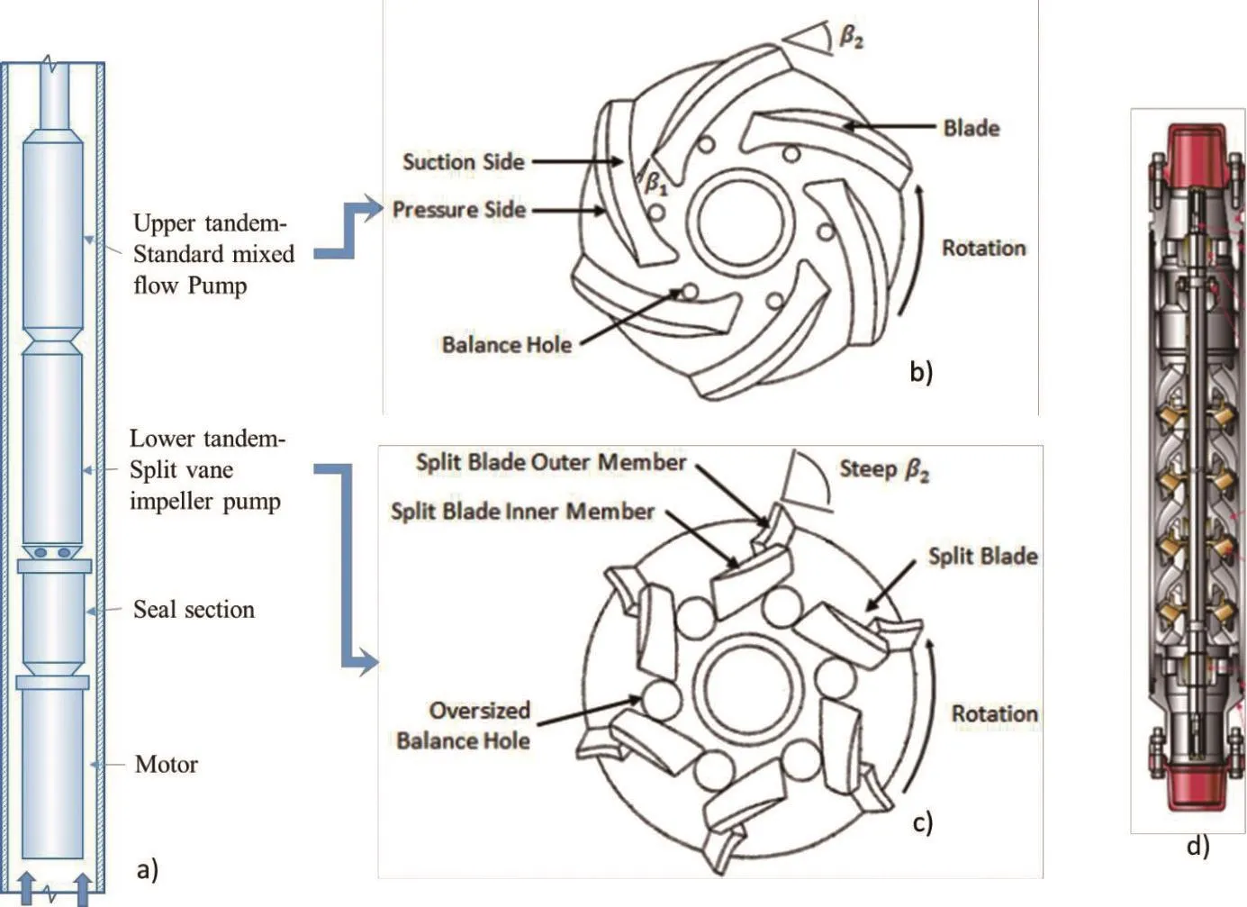
Fig.3 a)Typical configuration of downhole ESP system with gas handling stages b)Mixed flow impeller c)Split vane impeller(gas handler)d)Typical ESP pump section[5]

Fig.4 Experimental Setup Diagram[2]

Tab.1 Operating conditions for erosion testing for split-vane for 66 hours

Fig.5 (a)Sand sieve analysis
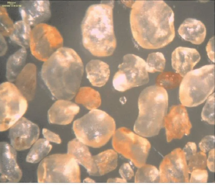
Fig.5 (b)Microscopic photograph[5]

Fig.6 Suction side(left)and pressure side(right)of water-airs and tested impeller split blade outer member[8]
Figure 7 shows the outer member of split vane impeller for the second stages for 0 and 20%GVF testing.In the case of 0 GVF testing,erosion rate was minimal and blade retained overall length.The outer member experienced significant erosion for 20%GVF testing.More than half of the blade of the first stage impeller was eroded;the leading edge was also significantly eroded.This may have been caused due to impingement of the sand particle with higher force due to various factors.Phase separation causing higher shear,higher turbulence due to the special design of the blades,and reduced lubricity due to gas accumulation may be the major factors.The presence of gas had a profound effect on the wear mechanism.Wear across subsequent stages was lower due to decreased GVF.Figure 8 shows that the hub sidewall for the water only test experienced significantly less wear than the 20%GVF.The shroud sidewalls experienced similar wear.
5 Diffuser wear
The wear mechanism across the diffuser was highly dependent on the impeller wear.Figure 9 shows the diffuser before and after 0%and 20%wear tests.In general,the pressure sides of the vanes experienced more wear than the suction sides due to direct impingement of particles.However,the suction side of the diffuser vane leading edges did experience significant wear as can be seen in Figure 9.The leading edges of the diffuser vanes for water-only tests experienced significantly different wear patterns than the 20%GVF tests.The water only diffuser vanes showed uniform wear near the leading edges while diffuser vanes for 20%GVF showed nonuniform wear near the leading edges.The nonuniform wear was likely caused by recirculation zones,predominantly liquid regions and predominantly gas regions present due to gas presence.
Along with leading edge wear,diffuser casing was perforated in the case of water-sand testing.Wall perforation was less significant in the case of 20%GVF testing.Overall wear rate appeared to be higher for water-only test.This difference between the wear can be attributed to the amount of energy supplied to the particles by the impellers.For the water only test,the impeller split blade outer members kept their general geometry and constantly supplied a large amount of energy to the particles.For the 20%test,the impeller split blade outer members were worn through their thickness and accordingly supplied less energy to the particles as the test progressed.The above explanation suggests that both diffusers were being worn at the same rate at the beginning of the testing;however,as the testing progressed,the diffuser tested at 20%GVF began to wear slower than the diffusers used for 0%GVF.
6 Seal Wear
Figures 10 and 11 show wear across front and back wear ring seals of the 1ststage impeller at 0%and 20%GVF testing,respectevely.The wear at the front seal stage surfaces was significant compared to back seal surfaces due to higher pressure drop and possibly higher sand concentration.Also,the wear on a stage seal surfaces was reduced with increase in GVF due to reduced pressure drop.For 20%GVF testing,the 1ststage impeller seal had insignificant wear compared to 2ndstage seal.Highest wear was observed in the stage tested at 0%GVF due to higher pressure drop causing

Fig.7 Untested(left),water-sand tested(middle),and water-air-sand tested(right)second stage split blade outer member.[8]

Fig.8 Untested(left),water-sand tested(middle),and water-air-sand tested(right)second stage hub sidewall[8]
high shear and possible higher sand concentration.So,for 0%GVF,the primary root cause of pump degradation is due to the wear across secondary flow paths.
7 Bushings Wear
The bushing dimensions were taken at 0 and 66 hours.Bearing radial clearance for 0%and 20%GVF testing is shown in Figure 12.Since the top bearing was fixed,the erosion of the bearings becomes severe along the shaft from top to the bottom.Overall bearing wear rate is increased due to presence of gas.
The microscopic pictures of the bearings after 66 hours of erosion 0%and 20%GVFs are shown in Figure 13.The major difference is the well-ordered array of stress cracks covering the entire surface in the case of 20%GVF,while bearings with water only testing did not experience such type of wear.It is hypothesized that these cracks are caused by thermal stress occurring when the bearing surfaces rub in the presence of air,heating the surfaces causing them to expand.Due to the low thermal conductivity of the tungsten carbide,the inner regions remain cool and are fractured due to the expansion of the outer surface[5].The depth of the fine cracks has not been established at this point.But,if they significantly penetrate the radius of the bushing,the structural integrity of the bearing will be greatly reduced.Also observable are circumferential gouges due to sand particles entering the bushing and being dragged around it while being compressed by the orbiting motion of the bushing.
Figure 14 shows the 2ndstage impeller orbits time trace and corresponding frequency spectrum for the test with 20%GVF at 0,43,and 66 hours.The orbit size of a 150 micron(6 mil)radial amplitude indicates this bushing is already touching and with the presence of gas it is unable to sustain the load generated by the pump.The frequency spectrum initially consists of the pump operating speed(60Hz)plus harmonics.Due to increased wear at 43 hours,increase in the amplitude of the fundamental frequency was observed.Also a well-defined subharmonic peak was originating around 50 Hz.As the erosion continued to 66 hours,subharmonic shifted to the lower frequency(45 Hz)while the fundamental frequency was slightly decreased.As the bushing clearances increased the subsynchronous whirl significantly increased leading to an even higher wear rate.
8 Pump Performance Comparison
Overall wear of the pump stage components affected the pump performance,however,specific failure due to the inlet condition had different impact on the pump performance.Figure 15 shows the pump head variation with run time.The pump head for the 20%GVF test has a 50%reduction over the 66 hours,while the pumps in 0%GVF test shows much smaller head losses.For the 20%GVF test,in its working condition,the 1ststage has lost almost all its head,the second stage shows more than a half of the head loss,and the third stage shows about 18%head loss.In the 0%GVF test,the head loss in its working condition is too small to identify.Typically,head change is mainly caused by pump geometry change due to erosion,inlet GVF and inlet pressure.Thus the head change cannot be evaluated merely based on erosion without considering the working condition difference(inlet GVF and pressure).Moreover,regarding the different stage number in these tests,and different erosion on each stage,it will be more convincing to compare the“change”on each single stage than on the overall pump.For this specific pump it is important to note that with 0%GVF the pump will erode most in the secondary flow paths while increasing GVF shifts this to the primary flow path,changing the area of dominant wear and pump failure.

Fig.9 Untested(top),water-sand tested(middle),and water-air-sand tested(bottom)second stage diffuser.Inlet views are displayed on left and a close-up inlet view of two diffuser vanes are displayed on right[8]
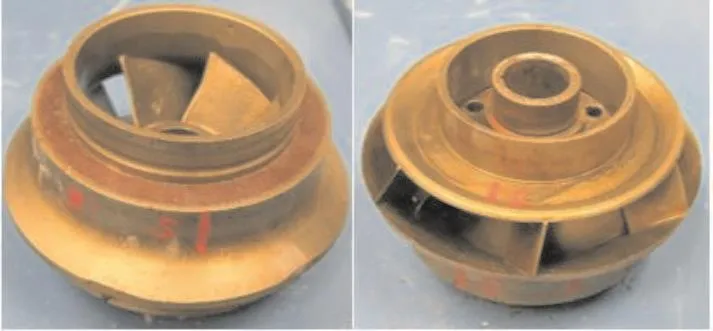
Fig.10 Erosion on wear rings at both sides of 1st impeller for 0%GVF test
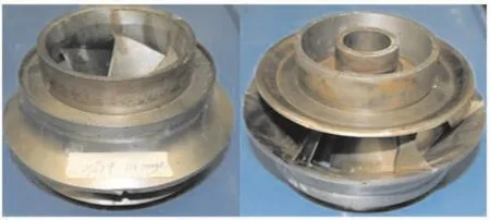
Fig.11 Erosion on wear rings at both sides of 1st impeller in 20%GVF test

Fig.12 Comparison of radial clearance in the 0%~20%GVF erosion test

Fig.13 Microscopic observation of bearings after each experiment

Fig.15 Pump performance variation with time for 0%and 20%GVF
9 On Improving the Pump Reliability
Decline in oil prices is driving the industry to explore for innovative ways to optimize oil recovery and improve the reliability of existing system.One of the traditional approaches is to quantify the reliability of individual components in order to assess and improve the system level reliability.The Turbomachinery Laboratory at the Texas A&M University is developing the test capabilities to evaluate the reliability of critical components such as seal sections,bushings,and thrust bearings.The Following section outlines some of the current and future work at the Turbomachinery Laboratory.
10 Seal Section(Future work)
The seal section,isolating the motor from the pump section,includes multiple types of seals but mainly rely of mechanical seal to prevent leakage of process fluid into the motor filled with mineral oil.For compression-type ESPs,a thrust bearing at the bottom of the seal section reacts the thrust generated by the pump section.The thrust bearings,isolated from the process fluid and submerged in the oil from the motor section,can sustain unit loads above 5 MPa.This unit load levels are larger than those found in state of the art land-based machinery.Mechanical seal failures in ESPs can lead to motor and/or bearing failures.The occurrence of failures in this application may also be exacerbated by the low pressure differentials applied to the seals.The bearing failures occur due to the contamination of the lubricant and the inability of the standard peek thrust bearings to handle the contaminants(water,sand,gas)while retaining its load capacity.
Two fundamental approaches are currently being pursued to improve the reliability of the seal section.The first one is to increase the tolerance of the mechanical seals to large vibrations while operating with low pressure differentials.Figure 16 shows the conceptual design of a test rig for investigating the conditions leading to mechanical seal failures,corresponding failure modes,and possible design modifications to improve robustness of these mechanical devices.For the first configuration,Figure 16a,two pair of electrohydraulic shakers will impose multi-frequency excitations to the shaft simulating the expected ESP vibration signature as the one shown in Figure 14,for example.Figure 16b shows the floating housing configuration.This set up will be used to evaluate the effect of casing vibration on the performance and reliability of mechanical seals.The seal rotating component displacement will be monitored with capacitance sensors,as shown in Figure 16c,while stator component will be mounted on load cells for measuring torque and reaction forces.These results are expected to provide an insight into the dynamic performance of the mechanical seals used in ESPs.
Alternatively,the second approach is to evaluate the feasibility of using process-fluid lubricated thrust bearings.Multiple materials and designs will be evaluated in a vertical test rig capable of producing 40,000 lbf of thrust and test the bearings to failure.These include Polycrystalline diamond(PCD),braze hard faced Tungsten Carbide and Silicone Carbide.Figure 17 shows a conceptual design of the thrust bearing test rig including a bottom and top chambers housing the slave and test bearing,respectively.The water-gas-sand lubricated test bearing load will be increased gradually until bearing failure while measuring pad temperature,force and film thickness.
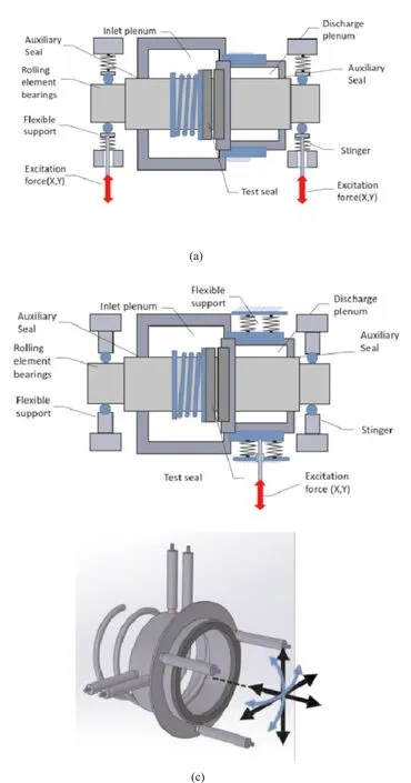
Fig.16 Mechanical seal component level rig concepts,a)flexible rotor support/fixed housing,b)fixed rotor support/flexible housing,c)seal displacement measurement arrangement.

Fig.17 Thrust bearing test rig conceptual design.
11 Conclusions
Erosion testing of split vane impeller pump was conducted at 0%and 20%GVF.Presence of sand had a profound effect on the wear mechanism across various components of pump.Presence of gas mainly affected the wear across impeller and bearings.Impeller blades significantly eroded causing the primary reason for pump performance degradation.Erosion at the diffuser inlet was directly affected by the erosion of outer impeller blade at 20%GVFs.Low erosion of outer blade of an impeller at 0%GVF resulted in higher wear at the diffuser inlet causing wall perforation.Front and back wear ring seal wear was higher at 0%GVF testing due to high pressure drop causing high particulate velocities.Bushing wear was mainly affected by the presence of gas causing heat checking due to direct rubbing of bearing surfaces.Bushing wear significantly increased whirl vibration amplitude,which further accelerated the bushing surface degradation.
Component-level test rig for evaluating reliability of mechanical seals and process fluid-lubricated bearings was presented.The mechanical seal will be subjected to large vibration amplitudes(250 microns)while monitoring seal displacement and reaction forces.The thrust bearing will be loaded with unit load above 5 MPa while lubricated with water,gas and sand.In both cases,the components will be tested to failure.
12 Aknowledgements
Authors would like to thank Royal Dutch Shell for their financial and technical support.
杂志排行

风机技术的其它文章
- Aerodynamic Performance Optmization and Data Mining of a Low Pressure Exhaust Hood
- Optimal Design of Non-axisymmetric Endwall with Variable-fidelity CFD Model*
- Shape Optimization of a Modified Centrifugal Compressor Using the Adjoint Method*
- 超临界CO2离心压缩机性能预测及损失模型研究*
- 某长输管线离心压缩机模型级开发**
- A Review of Computational Aeroelasticity of Civil Fan Blades