Shape Optimization of a Modified Centrifugal Compressor Using the Adjoint Method*
2018-11-21
(BeijingInstituteof Technology,Beijing,China,E-mail:jilc@bit.edu.cn)
Abstract:Centrifugal compressors can realize a high pressure ratio within a relatively small spatial space,therefore largely used in aviation impeller machinery.Pursuing less size and weight while no penalty of efficiency and aerodynamic loading is the development trend,while both the complex geometry and tough flow conditions bring challenges on the flow calculation and aerodynamic shape optimization. Considering the Adjoint method is an efficient local optimization algorithm,this paper uses the continuous Adjoint method to optimize the geometry of a modified Krain impeller. The results show that the isentropic efficient is improved 0.53%point at near peak-efficiency operating condition,while the mass flow rate and total pressure ratio keep relatively constant.Besides,the whole characteristic line shows a positive improvement, indicating the significance of the Adjoint optimization method
Keywords:Optimization,Adjoint Method,Centrifugal Compressor,Krain Impeller,Entropy Generation Rate;Isentropic Efficiency
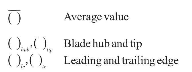
Nomenclature
Symbols


Superscripts and Subscripts


1 Introuduction
Centrifugal compressors are important components in turbocharges and turboshaft engines as they can facilitate a high pressure ratio within small spatial requirements.Compared with axial compressor,centrifugal compressor is more complex because of the complex internal flow field. Nowadays, improving the efficiency while reducing the size and weight is the trend of centrifugal compressor,which determines the important status of optimization.Considering most optimization methods have a characteristic that the calculation amount is severely influenced by the number of design parameters,for de-tailed optimization,which means the design parameters’number is usually large, the computational cost is a factor that can’t be ignored.
The most significant characteristic of the Adjoint method is that its calculation cost has nearly no relationship with the number of design parameters,which makes the Adjoint method a popular optimization method in both external and internal flows[1-17].The Adjoint method is a kind of gradient-based algorithm,which mainly uses the sensitivity information to determine the optimization direction.
The derivation of the Adjoint equation can expressed as follows:Introducing the adjoint stateλas a Lagrange multiplier to enforce the flow governing equation,the objective function becomes:

HereIis the objective function.Ris he flow governing equation andαis the design parameter.Then the gradient of the new objective function can be written as:

Considering the linearization of flow governing equation,the sensitivity can be expressed as:

So a conclusion can be got that:
If a properλexists to make that:

then the sensitivity can be computed through:

So if a proper distribution ofλcan be obtained to satisfy Equation(4),the expression of sensitivity will be independent ofUα,which makes the sensitivity calculation greatly simplified since it doesn’t need to compute the gradients of flow terms.
Replacing the flow governing equation with the thin layer RANS equation,and fulfilling the derivation process in equation(1)-(5),the specific expression of the Adjoint equation is that:

And the gradient of the objective function to design parameters can be expressed as[16]:
According to the Adjoint method described in equation(6)and(7),our team developed an Adjoint optimization system to optimize the geometry of turbomachine and the existing optimization results showed good properties. In this paper, the optimization system is adopted to optimize a modified centrifugal compressor.
2 Geometry Description
In this paper,a centrifugal compressor setup by Krain et al[18],which is based on the experiment with a high pressure ratio,is chosen as the geometric model. The design parameters of impeller are shown in Table(1).And further details can be taken from[1].

Tab.1 Impeller design data SRV2-O
However,when the original Krain impeller was calculated by our flow solver in the Adjoint optimization system,the numerical errors are relatively larger,and the poor characteristic of flow is not suitable for optimization process.Therefore,the geometry of Krain impeller is modified to satisfy the whole optimization solver. Changes are concentrated on the area of leading and tailing edge and the flow path. For the former, the structure of leading and tailing edge are modified into rounded,as shown in Figure (1).As for the latter, the flow path is shorted artificially,as shown in Figure (2).
Now we call the original Krain impeller with rounded leading and tailing edge as the original geometric model.And the Krain impeller with shorted flow path and rounded leading and tailing edge as the new original geometric model. Calculated by Numeca software, the performances of original and new original models are shown in Figure (3).


Fig.1 Modified structure of leading edge(left)and trailing edge(right)

Fig.2 Modified flow path of Krain impeller

Fig.3 Performance of the original model(left)and new original model(right)impeller.
In Figure(3),the mass flow rate is normalized by its choked values.The maximum stage pressure ratio is 6.8 with a corresponding isentropic efficiencyηof about 78%in the original geometric model.In the new original geometric model,the maximum stage pressure ratio is 7.3 with a corresponding isentropic efficiencyηof about88%.From the point of geometry,the new original model has much shorter inlet and no vaneless diffuser, and therefore less loss is occurred in the latter model and the isentropic efficiency is much higher. At the same time,although the calculation settings of inlet boundary conditions are the same,the defined inlet positions are not the same,so actually the real inlet boundary conditions are different,which can explain the phenomenon of different stage pressure ratio.
The optimization process in this paper aims at changing the geometry of the main blade and splitter to get an adjusted geometry with higher efficiency.Considering the optimization space and the correspondence between two original models,the new original geometric model is chosen as the starting point of the Adjoint optimization.
3 Optimization Settings
3.1 Parametric model
The parametric model defines the changing pattern of optimization space when perturbations are added to the design parameters.In this paper,Hicks-Henne bump function[19]used to explore the design space composes of blade circumferential bowing and blade suction surface.
The Hicks-Henne function used in this paper can be expressed as:

wherexle,xteare the axial coordinates of the leading and trailing edges;rhubandrtipare radial coordinates of hub and casing section.
The geometry of blades is described inr-θ-xcoordinates.According to equation(20),once one design variable has a perturbation,geometry at its position has a maximum change compared to other positions.At the same time,the geometry of other positions has changes too,which is decided by the relative distance to the perturbed design variable.
3.2 Objective function
Generally,the expression of isentropic efficiency is too complex to be used as objective function in optimization process.Considering the corresponding relationship between aerodynamic efficiency and entropy generation rate, and the expression of the latter is much simpler[20],in this paper,entropy generation rate is chosen as the objective function for the optimization process,which can be expressed as:

The definition of the entropy generation rateΔsis given by:

where the subscript“in it”denotes initial values of the new original geometric model.
3.3 Cost function and constrains
In essence,the Adjoint optimization method belongs to a mathematical way.The control of optimizer mainly reflects on the optimization function and parametric method.To get a better optimization direction,usually we need to add some constrains to the objective function,which means the cost function.Generally,such constrains include the mass flow rate,total pressure ratio and flow angle. In this paper, the cost function is chosen as equation(11)to prevent the changes of the flow characteristic point.

Wherem˙and πare the ratios of mass flow rate and total pressure ratio,respectively.σ1andσ2are weighting factors,which describe the control ability of each constraint.
So the final objective function used in this optimization is:

4 Results and Analysis
The design optimization is carried out at near peak-efficiency operating point,whose performance is listed in Table(1).Total 242 design variables are used to describe the shape perturbations of the blades,including 11 design variables describing the stacking line of the blade.
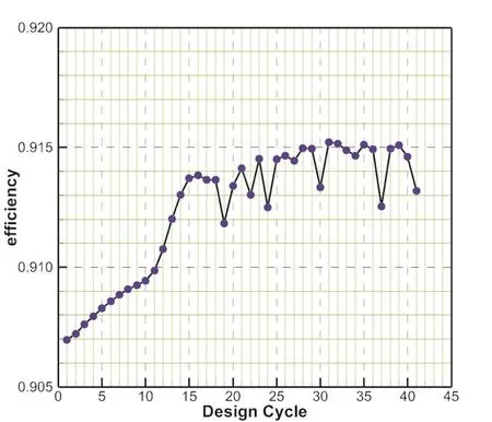
The evolution of the entropy generation rate with design cycles is shown in Figure(4).From the viewpoint of the changing trend of the entropy generation rate,the optimization system realizes the target of decreasing the entropy generation rate.As the same time,shown in Figure(5),the isentropic efficiency calculated by flow solver in the Adjoint optimization system achieves the growth as a whole.The constrains of flow mass rate and total pressure ratio in equation(11)are used to keep the operating conditions constant,whose evolution is shown in Figure(6).Although the value of mass flow rate and total pressure ratio keep changing with cycles,the maximum change during the whole optimization is 1.40%of total pressure ratio and 2.50%of mass flow rate.At the fourteenth optimization step,the changes of constraints are 0.49%of pressure ratio and 1.99%of mass flow rate,which are all in the acceptable ranges.

Fig.4 Evolution of the entropy generation rate

Fig.5 Evolution of the efficiency

Fig.6 Evolution of the constraint of mass flow rate and total pressure ratio
Choosing the fourteenth optimization step as the final optimization result, which is the last point before the entropy generation rate starting shaking. The difference of geometric structure between the new original model and the optimization result is shown in Figure(7)and(8).As we can see from the figures,at the region of hub and tip,the changes at leading edge are bigger than tailing edge. The profiles of the splitter move to the pressure surface while the profiles of main blade move to the suction surface.The changes of the splitter are larger than the main blade.At the mid span,changes are the most obvious.On the whole,the changes of profiles increase the area of flow path between the main blade and its upper splitter.

Fig.7 Comparison of blade geometry(x-rθ)between original and optimal at hub and tip span

Fig.8 Comparison of blade geometry(x-rθ)between original and optimal at mid span
After calibrating the flow by Numeca software,the changed geometry makes the flow field getting a better performance,as shown in Figure(9)and(10).The relative Mach number near the leading edge of the main blade is decreased, reducing the strength of shock at that region at mid span.Besides,the area of low Mach number near tailing edge is decreased at both the mid span and the 90%span.Though the changes are not big enough,the isentropic efficiency still improves 0.53%point.In another word,the Adjoint optimization improves the flow structure on detail but didn’t change the nature of the flow.

Fig.9 Contours of relative Mach number on blade to blade at mid span

Fig.10 Contours of relative Mach number on blade to blade at 90%span
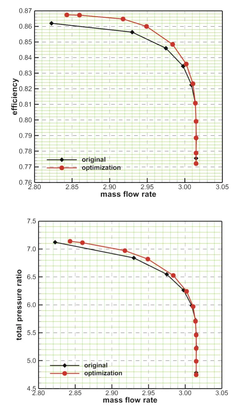
Considering the performance at a single operating point can’t represent the working ability of the centrifugal compressor,the comparison is with the impeller global data,i.e.pressure ratio and efficiency vs.mass flow rate,as shown in Figure(11).It is clear that the performance of the optimized impeller near the choked point is the same as the new original model.However,both the efficiency and total pressure ratio have a significant increase at the non-choked conditions.And the maximum increase of efficiency calculated from the characteristic line is about 0.6%, showing the positive function of the Adjoint optimization system.

Fig.11 Efficiency and pressure ratio over mass flow rate
5 Conclusions
In this paper,a constrained gradient evaluation is used for centrifugal impeller,and a continuous Adjoint method for the thin shear-layer N-S equations in a cylindrical-coordinate system is developed.With the Adjoint-based gradient evaluation,perturbation-based shape representation,and the steepest descent method,an efficient integrated shape optimization loop is constructed.
The proposed method is used to optimize the shape of the Krain impeller.The optimization is able to raise the isentropic efficiency of the blade by 0.6%while maintaining nearly the same mass flow rate and total pressure ratio.Though the improvement of the isentropic efficiency is not such significant, it provides a new way to improve the centrifugal impeller.
6 Acknowledgments
The authors would like to express their deep appreciations to the National Natural Science Foundation of China for funding this work,Project No.51676015.
