A Review of Computational Aeroelasticity of Civil Fan Blades
2018-11-21
(Department of Mechanical Engineering Imperial College,London,SW7 2AZ,m.vahdati@ic.ac.uk)
Abstract:The aim of this paper is to present the state-of-the art in computational aeroelasticity methods that are available for analyzing fan blades on modern civil aircraft.Fan blades in modern high-bypass aero-engines typically produce around 80%of the thrust.In order to improve specific fuel consumption and reduce the level of noise emitted from the engine,civil turbofan engine designs are moving toward even larger fan diameters with lower tip speeds and hence the importance of this component of aero-engine becomes even more prominent.To reduce weight,future fan blades will be made of composite materials and shorter intakes are used. The new designs are highly loaded and will be more susceptible to aerodynamic and aeroelastic instabilities,and hence computationally efficient aeroelastic modelling tools for such blades are paramount.
Keywords:Unsteady Aerodynamics,Aeroelasticity,Flutter,Bird Strike,Inlet Distortion,Forced Response
Nomenclature
MrefNon dimensional mass flow function
1 Introuduction
There is fierce competition amongst aero-engine manufacturers to supply tomorrow’s aircraft with engines that are lighter,quieter and more efficient than the ones used today. Current designs are approaching their limit in efficiency and noise,and to achieve significant improvements new design concepts are required.An example of such a design is the geared turbofan,which allows the turbine, driving the fan, and the fan to rotate at different speeds.Therefore,each component can rotate at its optimum speed and larger diameter fan blades,rotating slower than current blades,can be employed.The new fan design is expected to be 25%more fuel efficient and to reduce noise levels by 15dB,which is line with ACARE 2050 targets.To reduce weight,the new fan blades will be made of composite materials.The light flexible fan blades are highly loaded and will be prone to air induced vibration(aeroelasticity)and hence require novel design methods.Moreover,as the fan(and hence intake)diameter increases,shorter intakes are required to reduce the overall weight and drag of the aircraft[1-2].As a result of shorter intakes, the fan and the intake are more closely coupled and hence the effects of inlet distortions, such as crosswind,are becoming more important for fan stability[3].Moreover,such fan blades are highly loaded and tend to operate on the flat part of the constant speed characteristic,thus are more prone to aerodynamic and aeroelastic instabilities than conventional ones[4-6].
Since aeroelastic engine/rig tests are very expensive(especially in case of failure)and time consuming,computational simulations are increasingly used in engine development.Computational modelling also offers advantages for studying the causes and mechanism of aeroelastic instabilities because they allow independent variation of a number of parameters,which would often be fixed in an experimental investigation.
In this paper,three forms of aeroelastic vibration that can affect fan blades are studied.These vibrations are part-speed stall flutter,forced response due to inlet distortions and aeroelastic vibrations as a result of bird strike.In each case,the physical phenomena which causes the vibration is presented and the possible numerical modelling approaches are discussed.
2 Test Case and Numerical Model
The fan assemblies under investigation are typical wide=chord modern designs for large-diameter aero-engines.The hub-tip ratio is around 0.3 for all the cases and the tip Mach number varies between1.0and1.3.
2.1 Flow solver
The CFD code used for this work is AU3D[7],which is a three-dimensional,time-accurate,viscous,compressible URANS solver,based on a cell-vertex finite volume methodology and mixed-element unstructured grid.The current computations use the one-equation Spalart-Allmaras(SA)turbulence model[8].It is well known that the standard SA model overpredicts the size of separation zones which leads to blockage of passages,a considerable total pressure loss and premature stall[9-10].The situation becomes worse for blades which have flat characteristics such as a low-speed fan. In order to suppress unnecessarily large separation zone,the production term is modified based on the pressure gradient[11]and velocity helicity[12].The parameters in the modified SA model are held constant in all the present work.More details,methodology and validation,can be found in Ref.[12].The resulting CFD code has been used over the past 20 years for flows at off design conditions with a good degree of success[13-17].
2.2 Computational domain and boundary conditions
The domain used for the unsteady aeroelastic computations includes the complete fan assembly with OGVs,ESS,a symmetric intake upstream of the fan,and an external volume which contains the rig,as shown in Figs.1(a)and1(b).The free stream boundary of the computational domain was placed 13 intake lengths away from the intake(see Fig.1(a)),which is(numerically)far enough to remain undisturbed by the fan.The grid used for the intake is unstructured(Fig.1(c))and was generated using the commercial package GAMBIT.Ano-slip condition is imposed on the intake casing and spinner walls.The grids used for the blading are semi-structured,with hexahedral elements in the boundary layer region around the aerofoil,and prismatic elements in the passage.The radial grid,containing 49 mesh layers,is refined toward hub and casing to resolve the end-wall boundary layers.The fan is modelled with a typical rig blade tip clearance and is modeled with 6 radial levels in the tip gap.The total number of grid points used in this study contains about1.7×107nodes.
The flow through the fan is controlled by placing two choked variable-area nozzles downstream of the fan[18].The nozzle downstream of the ESS controls the bypass/core flow ratio and is fixed at each speed.The nozzle downstream of the OGVs allows the computation to be conducted at any point on the constant speed characteristic by simply modifying the nozzle area.As the flow is choked in the nozzle, the solution will be independent of the conditions specified at the nozzle exit.The operating conditions considered correspond to sea level static conditions.These conditions are specified at the far field boundary(see Fig.1(a)).In all the unsteady computations,the interface boundaries between stationary and rotating blade rows are modeled as sliding planes.
2.3 Flutter
It should be noted that the work presented in this section is a summary of previous work by the authors[16,17,19-23],and for further details the reader is referred to these papers.
This section describes the aeroelastic instability leading to what is commonly called stall flutter for a fan blade.Although called stall flutter,this phenomenon does not require the stalling of the fan blade in the sense that it can occur when the slope of the pressure rise characteristic is still negative.This type of flutter typically occurs at part-speed operating conditions,in low nodal diameter forward traveling waves and in the first flap (1F) mode of blade vibration. Discussion in this paper is restricted to the flutter of fans which have no part-span shrouds,such as those used on modern aircraft engines.Flutter can occur when the pressure ratio of the fan is increased beyond its normal operating range,by reducing the mass flow through the fan.In such cases,the onset of flutter,rather than stall and surge,forms the limiting operating condition. In such cases the
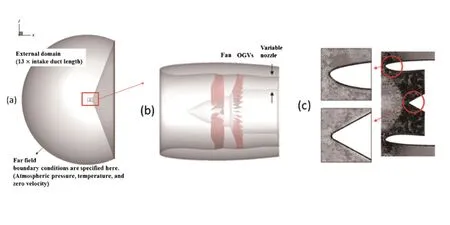
Fig.1 Domain used for the computations presented here
stability boundary of the blade is defined by the minimum of the stall and flutter boundary.For specific narrow speed ranges,flutter is seen to remove a‘bite’from the stable operating condition of the blade-hence the term‘flutter bite’.This phenomenon is clearly illustrated in Figure 2.In this plot,pressure ratio(as defined by the ratio of total pressure at trailing edge to that at leading edge)is plotted against inlet mass flow function.Also shown in this figure are lines of constant fan rotation speed(characteristics)and the design working line.It is seen from this plot that the flutter bite can remove a significant part of the stable operating region and moreover,it can bring the stability line very close to the design working line.Therefore,two situations that should be avoided are:
1)The working line cutting through the flutter bite,as shown by the dashed red line (labelled‘High working line’)in Fig.2.
2)The design speed cutting through the flutter bite.In the plot of Fig.2 there is a gap between the flutter bite and the design speed.
In the remainder of this section,the physical phenomena that contribute to the flutter bite are discussed.
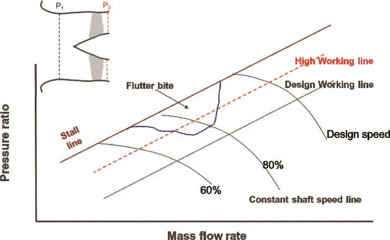
Fig.2 Demonstration of flutter bite
In[16],CFD was used to explore stable and unstable behaviour of a high-speed fan. The fan is a model which has been operated in a rig and is representative of the type of fan used on recent large engines.Numerical simulations are used rather like an experimental technique,varying input parameters to give insight into the effects controlling the onset of flutter.The calculations in this report assume no reflections,corresponding to infinitely long intake and exhaust ducts.This approach will isolate the fan and can be used to determine the flow and structural features which cause flutter.
Before proceeding with a description of flutter,some basic wave propagation terms need to be introduced. Blade vibration creates unsteady flow perturbations which can be grouped into three types of waves:entropic,vortical,and acoustic[24].Entropic and vortical waves can only convect in the downstream direction, whereas the acoustic waves may propagate in the upstream as well as downstream directions.An acoustic wave is termed cut-on if the wave can propagate in the axial direction without attenuation,whereas an acoustic wave is termed cut-off if it decays exponentially from the source.For more information regarding turbomachinery noise and acoustic propagation in ducts the reader is referred to the seminal paper by Tyler and Soffrin[25].
Fig.3 shows the computed part-speed characteristic and aerodynamic damping plotted as a function of mass flow.The mass flow and pressure ratio are non-dimensionalised by their values at the design condition.It is seen from this figure that the aerodynamic damping becomes negative,i.e.flutter occurs,as the pressure ratio of the fan is increased(mass flow is decreased)beyond its normal operating range.It can be seen from Fig.3 that for this test case the onset of negative damping occurs at a mass flow of 0.95.As there is no intake in these computations,this type of flutter is referred to as‘blade only’. In reference[16]the main aerodynamic,acoustic and mechanical features which result in‘blade only’flutter were identified.They were:
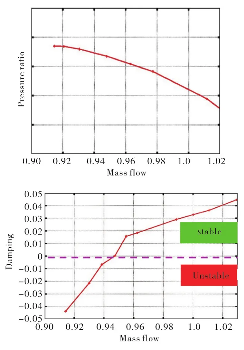
Fig.3 Constant speed characteristic at flutter speed(a),and damping as a function of mass flow at flutter speed
1)Aerodynamic effects, characterised by flow on the suction surface of the blade.
It was shown in[4,5]that the part span separation on the suction surface of the blade and the consequent radial migration of flow is one of the main drivers for flutter instability for this blade(as demonstrated in Fig.4).In this plot,the Mach number is shown on the suction surface of the blade at flutter speed,for a stable mass flow(mref=0.97)and an unstable mass flow(mref=0.93).Surface streamlines are also superimposed on these plots. In this plot the flow direction is from right to left,as indicated byVx.For the stable case(mref=0.97)the flow is smooth and follows the blade profile whereas for the unstable case(mref=0.93)there is a part span separation at 65%span which causes radial migration of the flow.Also shown on this plot(Fig.4c)are radial profiles of damping. It is clear from this plot that for the stable case(mref=0.97)the aero-damping is positive(stable)for all the radial sections.For the unstable case(mref=0.93),most of the negative damping(unstable)region is outboard of 80%blade span which is outboard of the separation region (as shown by the arrow).
2)Aeroacoustics effects, characterised by the nature of acoustic wave generated by vibration.
It was shown that, as a pre-condition for flutter, the acoustic disturbances produced by the blade vibration must be‘cuton’(i.e.propagating)on the upstream side and‘cut-off’(i.e.the acoustic wave is evanescent)on the downstream side thus the blade can only flutter in a certain frequency range at each fan speed.In Fig.5 aero-damping is plotted against frequency for the 1F 2ND mode at mass flow 0.93.It clearly shows that aerodynamic damping is only negative when reduced frequency is between 0.62 and 1.02.The instantaneous unsteady pressure at 90%height at flutter condition is shown in Fig.5b.It clearly shows that the acoustic wave is cut-on upstream of the blade and cut-off downstream of the blade.
3)Mechanical effects,characterised by the amount of twist in the 1F mode.

Fig.4 Suction surface Mach number and radial profile of damping at flutter speed
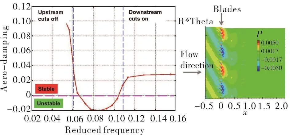
Fig.5 Aero-damping as a function of frequency(a),Instantaneous variation of unsteady pressure(b)
Fig.6 shows the mechanical mode shape for blade vibration,represented by contours of magnitude of displacement.Fig.6(a)shows the total motion.The displacement normal to the chord line near the tip,which is referred to here as plunging motion,is shown in Fig.6(b).The plunging component is obtained by averaging the displacement along each radial section.The twisting motion about an axis near the middle of the blade,obtained by subtracting the plunge of Fig.6(b)from the total displacement of Fig.6(a),is shown in Fig.6(c).As the figure shows,the 1F mode shape can be decomposed into a pure plunging and a pure twist motion.The twist to plunge ratio parameter(α)is defined as the product of the twist angle amplitude(in radians)times the semi-chord of the blade at the tip divided by the plunging amplitude at the tip of the blade and can be computed from ratio of LE to TE displacements[16].Fig.7 shows the variation of 1F/2ND damping at mass flow 0.93 as a function ofα.The datum value ofαfor this blade is 0.3.It is seen that as a increases the blade becomes more unstable(negative aero-damping increases).Therefore,it can be concluded that design of flutter free blades would require blades with lowαvalues.
In the computations shown above,AU3D,which is a nonlinear time domain model,was used to obtain the aero-damping of the blade.However the authors believe (also shown[19])that a linear frequency domain analysis would produce similar results,and will reduce computational time significantly.
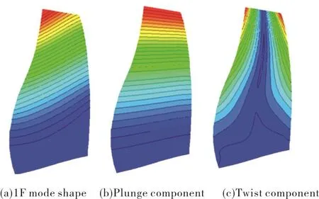
Fig.6 Contours of blade vibration:(a)is total motion,(b)is plunging motion(c)is the twisting motion;Contour levels are smaller for twisting motion

Fig.7 Variations of aero-damping as a function ofα
It was shown in previous work[21-23]that acoustic reflections from the intake play an important part in fan flutter and should be taken into account during the design of new engines.Fig.8 illustrates this interaction mechanism,showing that outgoing acoustic waves are reflected at the intake highlight.Fig.9 shows the aero-damping plotted against fan speed(tip Mach number). Also shown in this plot is the aero-damping for the case without an intake. The behavior of the case without intake (black curves) is only dependent on the flow on the blade and mechanical properties of the blade,as described in the preceding section.It can be seen from this plot that the reflections from intake can play an important role in flutter,changing the flutter stability of the blade significantly.This contribution to flutter is referred to as‘acoustic flutter’in this paper.

Fig.8 Illustration of acoustic reflections from the intake

Fig.9 Comparison of damping with and without intake
At the flutter condition,the intake length and mean Mach number determine the propagation time and thus the phasing of the reflected acoustic wave,which can be beneficial or detrimental to the overall stability of the fan system. It was shown in[22]that the most destabilizing case occurs when the upstream wave lags the reflected wave by 90◦and the most beneficial condition occurs when the upstream wave leads by 90°.In[23]a simple model that can be used to study the effects of intake on flutter was introduced.The results of the simple model were compared against those of AU3D and show a good agreement.
It can be inferred from the above that it would be possible to increase the flutter margin of the blade by introducing deep acoustic liners in the intake.The liners would have to be deep enough to attenuate the flutter induced pressure waves in order to influence fan stability.Acoustic liners are frequently used in the intake to reduce the level of noise emitted from the inlet of turbofan-engines,especially during landing and take-off.The properties of such liners (depth and resistance) are usually optimised for fan noise,which have much higher frequencies than flutter tones.However,it is known that acoustic liners with appropriate depth can stabilise flutter by absorbing the flutter wave energy[8].
It was shown in [21] that the contribution to aero-damping due to the blade motion(for the isolated rotor in an infinitely long duct)and due to intake reflection seem to be independent and so can be analyzed separately.Therefore,the design of a new intake can be assessed on its own,independent of the fan design.Moreover,worse flutter instability occurs when the‘blade only’flutter is at the same speed as‘acoustic flutter’due to the intake. It is obvious from this statement that it is possible to gain a significant improvement in flutter margin by designing a fan and intake system that separates the speed at which these two phenomena occur.
3 Forced Response Due to Inlet Distortions
The forced response of bladed-disks is a very common vibration problem during the development phase of new aero-engines.A primary mechanism of blade failure is high- cycle fatigue (HCF) which is caused by vibrations at levels exceeding material endurance limits. In the context of the forced response of a civil aero-engine fan, downstream obstacles such as OGVs and pylons give rise to blade passing frequency (BPF) forced response, and flow distortions due to nonaxisymmetric intake geometries, environmental conditions and angle of attack (during climb) give rise to low- engine order (LEO) forced response.The former type is relatively easy to deal with because the order of the excitation can be deduced from the number of blades. There are no straightforward methods for the latter type since the determination of low-order harmonics requires a detailed knowledge of the inlet flow. The actual vibration levels depend on three quantities: unsteady aerodynamic pressure,correlation of unsteady pressure with the mode shape and total damping (aero + mechanical) for the mode of interest. For previous research by the authors on distortion driven force response the reader is referred to [27,28].
This section describes the fan forced response under crosswind(the same principles apply during aircraft climb)which can lead to boundary layer separation at the inlet of the engine resulting in a non-homogeneous flow field upstream of the fan.Fig.10 is a schematic of flow past an intake during crosswind,with a streamline visualized near the intake lip.For high levels of crosswind the flow can separate on the intake lip and the level of distortion at the fan face is determined by the size of the separation.Fig 11 shows a schematic view of fan blade as it rotates around the annulus. It is seen from this plot that due to distortion a blade would experience different inlet conditions as it rotates around the circumference and hence the flow on the blade becomes dependent on its circumferential position.The corrected mass flow and total pressure ratio of a fan blade as it rotates around the circumference is shown by the dashed line in Fig.12.Also shown in this figure are the steady(undistorted)constant speed characteristics.It can be seen from Fig.12 that the distortionⅠ)moves the blade to a higher/lower speed line,as in part A and C of Fig.12 andⅡ)moves the blade along the constant speed characteristic, as in part B and D. The change in corrected mass flow is due to the presence of the distortion,which reduces the axial velocity in the distorted sector of the azimuth and can be explained with classical parallel compressor theory[29].Therefore in such situations the flow on the blade becomes unsteady which results in the blade experiencing unsteady forcing.

Fig.10 Schematic diagram of flow around an intake during crosswind

Fig.11 Schematic diagram fan inlet during one revolution

Fig.12 Operating point for one blade as it goes around the circumference
The time history of unsteady forcing on the blade together with its Fourier harmonics are shown in Fig.13(a)and Fig.13(b).It is seen from this figure that the forcing on the blade has many harmonics which correspond to multiples of the shaft speed frequency(also known as Engine Order).The unsteady forcing on the blade will result in blade vibration as demonstrated in Fig.13(c),which shows fan blade response levels during an acceleration.It is seen from this plot that both resonant and off-resonant responses are present during different parts of this manoeuvre. The crossing of EO forcing and blade natural fre
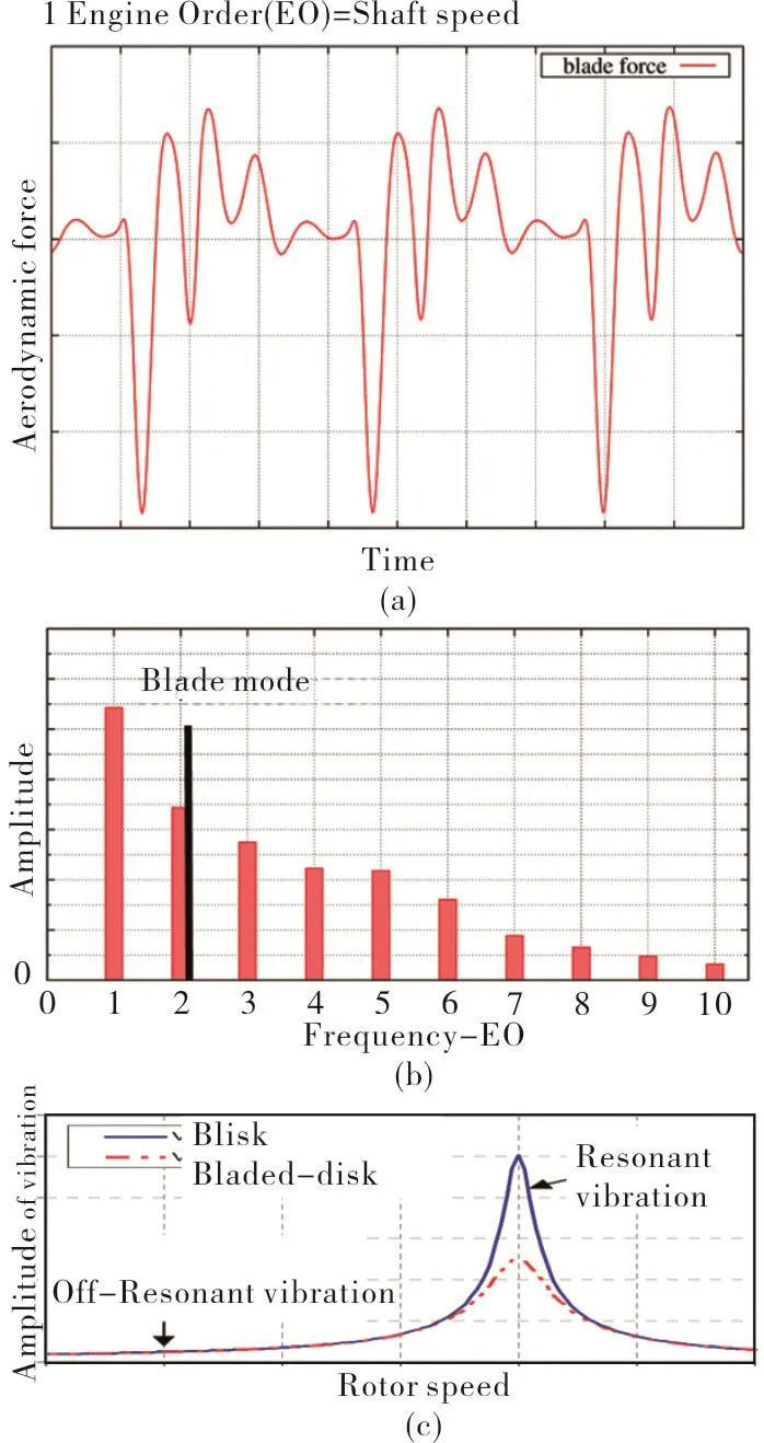
Fig.13 Unsteady forcing on the blade(a),Fourier harmonics of unsteady forcing(b),Blade response levels during an acceleration(c).
quency can be determined from the well-known Campbell diagram, as shown in Fig. 14. In the case of aero-engine fan blades,which may operate at very diverse conditions,it will not be possible to avoid all crossings of EO forcing and blade natural frequencies in the running range. These crossings relate to a resonant response from the fan blade.It should be noted that at cases with high levels of crosswind(as demonstrated in Fig.12)the amplitude of unsteady forcing can become extremely large which may result in significant off-response levels.

Fig.14 Campbell Diagram
A limitation of the Campbell diagram is that no distinction can be made between the resonant response levels that are likely to compromise the life of the component and those that can perhaps be tolerated,but in general two basic rules are followed:
1)There should be no crossing of 1EO and the first few vibration modes
2)There should be no crossings near the design speed.
Furthermore,blade-to-blade differences,which exist due to manufacturing tolerances,may cause an non-uniform vibration response among the blades.The response of the worst blade may be several times higher than that of the best blade.The standard practice is to base all predictions on a tuned assembly and to use a scaling factor for estimating the mistuning effects[1].
Finally,the use of titanium blade-integrated-disks(blisks)is becoming more common in modern civil aero-engine designs.Such structures have very low mechanical damping in contrast to traditional bladed-disk assemblies.For such structures,the main source of damping to the blade comes from the air flow.Fig 13c shows the comparison of response levels for a bladed-disked (in red) and a blisk (in blue). It is seen from this plot that the removal of mechanical damping would result in a significant increase in response levels,which highlights the importance of accurate prediction of blade response due to aerodynamic forces.
4 Bird Strike
Large-diameter turbofan engines are particularly susceptible to bird strike during both take-off and landing,an incident which can have extremely serious consequences. In September 1994,a US Air Force E-3Airborne Warning and Control System aircraft crashed as it departed Elmendorf,AFB,Alaska when both engines ingested birds.There were no survivors among the 24 occupants(Phillips[12]).Bird strike is a major consideration during the design of fan blades for such large-diameter aero-engines.Current methods rely on impact tests and structural optimisation but it is highly desirable to have predictive numerical models to assess the aerodynamic and aeroelastic stability of bird-damaged fan assemblies. Experimental evidence seems to suggest that bird damage may reduce the existing flutter margins and/or give rise to rotating stall cells,depending on the radial position of the damage,the number of blades that are affected and the actual operating condition.
The combined aerodynamic and structural modelling of a bird-damaged fan assembly is fraught with many difficulties.The flow representation must be time-accurate,non-linear and viscous.The turbulence model must be able to cope with flow separation and re-attachment.The unsteadiness due to the blade vibration must be included but the structural analysis is not straightforward because of gross mistuning.It must be stressed that the computational requirement for such a calculation is very considerable since a time-accurate,nonlinear viscous analysis must be undertaken for a whole assembly because of the loss of symmetry in the flow.
The aim of this section is to present such a methodology and to study a representative case.The particular fan assembly under investigation contained two consecutive blades with unequal impact damage,the so-called heavy-damage(HD)and medium-damage(MD)blades.Further details are given As shown in Fig. 15, the MD blade is leading the HD blade, the ordering being the reverse of that studied in[7].Although a bird strike is likely to occur during take-off,the aeroelastic analysis will be conducted at 70%engine speed. This replicates the situation where the pilot would reduce engine power in order to minimise vibration due to the rotating imbalance, while still retaining enough forward thrust for flight..

Fig.15 Schematic of‘bird strike’ test case
It should be noted that the purpose of the aeroelasticity analysis is to determine the stability of a damaged assembly and not to study how the damage occurs in the first place.Therefore,the structural analysis will ignore the transient loads and other effects such as blade rubbing on the casing. It will also be assumed that the blades have deformed plastically and a linear FE model without any residual stresses will be used to model the damaged geometry.Similarly,the gyroscopic effects will be omitted from the analysis,as they are not expected to have a significant effect on the nature of the outcome.On the other hand,disk and shaft flexibilities were included in the model as it was thought that such features were needed to capture the dynamics of the grossly mistuned assembly.This approach is in contrast with single sector analyses which are conducted for a single cantilevered blade. Even undamaged full-assembly analyses use a single cantilevered blade mode shape,albeit in expanded form.A view of the typical computed mode shapes for the test case is shown in Fig.16.A close inspection of the 1T family revealed the existence of three type of modes
1)Exhibit a nodal diameter pattern similar to an undamaged assembly Fig.16(a).
2)2)Exhibit a non-nodal diameter pattern Fig.16(b)
3)Only the damaged blades are vibrating,the other ones remaining stationary Fig.16(c).
Due to the complicated nature of flow in the damaged passage,it is not always possible to obtain a genuinely steady solution for the damaged assembly. Depending on the operating point of the fan, the flow can be either locally unsteady or inducing rotating stall,as is now demonstrated.The computed fan characterstic at part-speed for an undamaged assembly and the above damaged assembly is compared in Fig.17.It is seen that as a result of the damaged blades there is a considerable loss in performence of the fan.Moreover,it can be seen that the damaged assembly characteristic at each speed can be viewed as an undamaged characteristic at a lower speed and the damaged and undamaged characteristics diverge at higher working lines.Fig.18 shows the instantaneous Mach number profiles and reversed flow region at 90%height for operating point C1 on Fig.17.Due to the relatively low exit pressure at point C1,the flow separation is confined to the damaged passages and the global flow is assumed to be steady.The global steady flow refers to the fact that the overall mass flow and pressure ratio converge,however,as will be shown later the flow in the passage between HD and MD remains unsteady.Some relevant flow features can be identified from the Mach number plots of Fig.18(a)and negative axial velocity contours of Fig.18(b),these being plotted at the radial section of maximum damage.An inspection of Fig.18(a)reveals two regions of flow separation.Avery small one is situated at the leading edge of the MD blade while a much larger one blocks most of the passage for the HD blade.The blockage causes the flow arriving at the blade trailing the HD blade to have a large incidence angle.This causes a strong Prandtl-Meyer type expansion at the leading edge of that blade as the flow tries to turn a corner. The additional acceleration causes a larger and stronger shock on the trailing blade,thus decelerating the flow to such an extent that the shock on the blade trailing that one to be much weaker.
Fig.18 shows the negative axial velocity contours at 90%blade span during the time-accurate computations at Point C1.It is clearly seen from this plot the shape and the magnitude of stall region is a function of time.It is also apparent from this plot the unsteadiness is larger towards the trailing edge of the pressure surface of the trailing blade.Therefore,at lower working lines,the flow in the passage between the damaged blade and the trailing blade becomes unsteady,causing buffeting to occur.The unsteady pressures produced by buffeting on the trailing blade correlate with the 1T mode shape very well as can be seen in Fig. 20(a). It can be seen from this figure that the amplitude of the 1T mode is much higher on the trailing blade than other blades and in general 1T forcing is higher than the 1F forcing on the blade.Moreover,the buffeting has a range of frequencies,some of which are very close to the blade IT mode as shown in Fig 20.The interaction of unsteady pressure on the trailing blade can interact with the mode shapes of the type shown in Fig. 16c and cause local blade failure.
As shown in Fig.21,the situation is different for Point C2.A stall cell is formed at the leading edge of the HD blade and it propagates in the direction opposite to assembly rotation relative to the blades. It is somewhat difficult to define the number of stall cells since these are seen to disappear,split into smaller cells or merge into larger cells by‘catching up’with other cells.In any case,the stall cells do not cover more than 70%of the annulus at any time.Such a flow instability will clearly cause significant blade vibration.A closer inspection reveals that,due to the stall cells,the blades undergo a torsional motion by pivoting about their leading edge.This observation is in broad agreement with the traditional rotating stall argument of Emmons et al.[4]which is based on critical incidence.

Fig.16 Typical view of mode shape
Because of the complex behaviour,it is difficult to determine the speed of rotating stall.An approximate value may be obtained by considering the‘advancing front’of the rotating stall event,which shows they are moving away from the damaged blades at roughly30%shaft speed.
5 Conclusions

Fig.17 Comparion of fan performance between damaged and undamaged assemblies
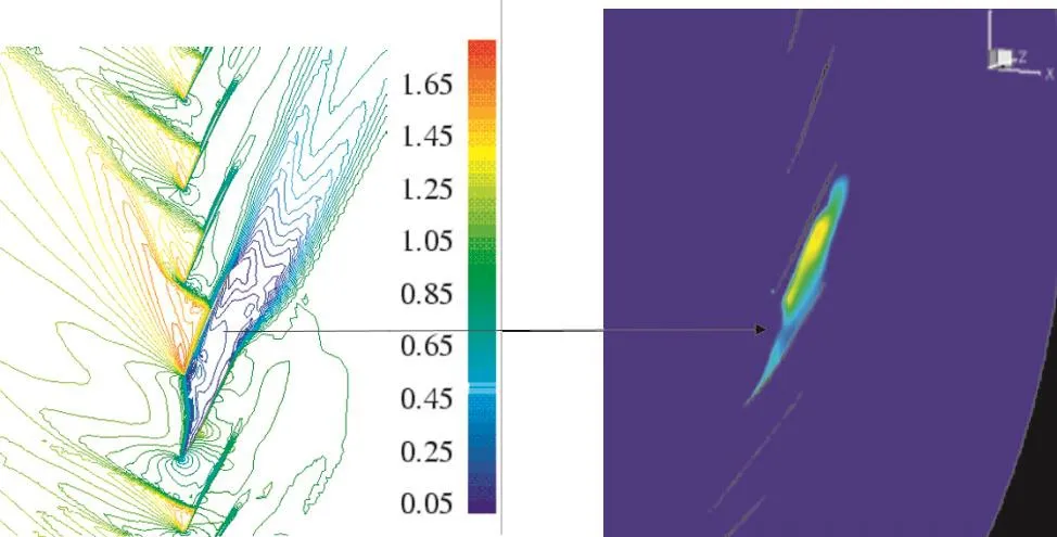
Fig.18 Instantaneous mach number profiles at 90%height at operating point C1(a)and reversed flow region(b)
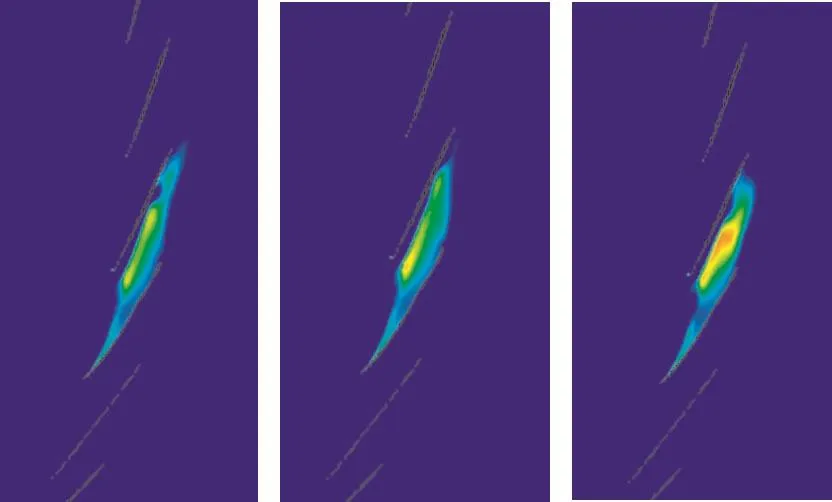
Fig.19 Variation of stalled region for operating point C1

Fig.20 Amplitude of 1F and 1T forcing on different blades(a),Fourier harmonics of 1T forcing on the trailing blade(b)

Fig.21 Time history of stall region at 4 instances of time at 90%height for operating point B
A bried synopsis of the wide scope of aeroelastic challenges in turbomachinery design have been outlined in this paper.The need to address such challenges is as critical as it has ever been,especially when one considers the ever-rising demand for air travel and the drive for efficiency improvements that are encroaching on the physical limits of fan blade stability.The commercial aerospace industry has committed to halving aviation-related greenhouse gas emissions from 2005 to 2050 and progress towards this target can only be achieved by the advent of more fuel-efficient aircraft engines designs.One of the examples highlighted in this paper, the use of blisks, is a prime example of such conflicting objectives. Blisks, which have inherently low mechanical damping,are becoming more common in modern aero-engine designs but this means flutter stability is now dominated by aerodynamic damping.In such a case,the accurate prediction of flow and the resulting blade response is necessary to inform understanding of the underlying mechanisms and also aid in blade design.Furthermore,this paper has outlined one methodology for performing such work.This paper has presented a review of past research that have used these computational methods for predicting the various phenomena associated with civil aero-engine fan blade aeroelasticity.Specifically,key mechanisms leading to isolated and installed fan blade flutter stability have been addressed and the impact of inlet distortion on fan stability has also been highlighted.Aeroelastic simulations for a geometry damaged by bird strike have also been touched on.The last set of computations required large amounts of computational power,but such computations are still relatively very cheap when compared to the experimental testing of blade failure events.All computations in this paper used the code AU3D which has been successfully used for aeroelastic computations for the last 20 years.It is envisaged that research in computational aeroelasticity will further increase in future.
6 Acknowledgements
The author thanks Rolls-Royce plc for both sponsoring this work and allowing its publication. The author gratefully acknowledges the contribution of colleagues who worked and who are currently working at the Vibration UTC Imperial College London and Rolls-Royceplc.
杂志排行

风机技术的其它文章
- Aerodynamic Performance Optmization and Data Mining of a Low Pressure Exhaust Hood
- Optimal Design of Non-axisymmetric Endwall with Variable-fidelity CFD Model*
- Shape Optimization of a Modified Centrifugal Compressor Using the Adjoint Method*
- 超临界CO2离心压缩机性能预测及损失模型研究*
- 某长输管线离心压缩机模型级开发**
- 鼠笼弹性支承应力分析与降低应力方法的研究*