Optimal Design of Non-axisymmetric Endwall with Variable-fidelity CFD Model*
2018-11-21LiuChenXuyangZhangRenDaiChengxiongPanMeibaoZhang
Liu ChenXu-yang ZhangRen DaiCheng-xiong PanMei-bao Zhang
(1.University of Shanghai for Science and Technology,Shanghai,China;2.Shanghai Electric Gas Turbine Company,Shanghai,China)
Abstract:Non-axisymmetric endwall is numerically investigated to suppress the secondary endwall flow in a HP turbine suction surface.The endwall contour is represented by a non-uniform rational B-spline surface.Two solution spaces are designed by the rule of hypercube sampling through variation of nodal radial extension. Final most effective endwall contour is obtained through screening all available samples with surrogate-based model. Results show that non axisymmetric endwall reduces the turbulence kinetic energy of the passage vortex by 5.5%and the total pressure loss 1.6%.Local heat transfer coefficient is lowered on the afore passage endwall surface with a certain increment on the aft passage endwall. Overall averaged heat transfer coefficient is reduced.
Keywords:Non-axisymmetric Endwall,Optimal Design,Turbine Rotor,Variable-Fidelity CFD Model
NomenclatureCaxAxial chord length
Second kinetic energy

VnNormal velocity
VzVelocity inzdirection
HHeight of the contoured endwall
Total pressure coefficient

pt,inTotal pressure at inlet
pt,inStatic pressure at inlet
ptLocal total pressure
Static pressure coefficient

psLocal static pressure
1 Introduction
The second flow in a turbine cascade is of interest to both designers and researchers. The flow in turbine rotor passages is strongly three dimensional due to the complex existence of secondary vortical flows. Close to the endwall, flow separation, a horseshoe vortex, a passage vortex, and some small but very intense corner vortices at the junction of the endwall and blade may affect the aerodynamic performance of a turbine and increase the heat transfer from the hot fluid to the blades and endwall surface(Wang et al,1997)[1].Thus,second flows have been studied for a number of decades and seminal works related to turbomachinery are presented by Langston(Langston et al,1977)[2],Sieverding(Sieverding,1983)[3]and Sharma(Sharma and Butler 1987)[4].When an endwall boundary layer approaches a row of turbine airfoils,due to a strong pressure gradient,it gradually collapses to two single vortices (a suction leg and pressure leg),which pair with oscillating motion extending downstream.The pressure leg of the horseshoe vortex travels across the passage toward the suction surface,becoming a major part of the passage vortex,which is also the major part of the secondary flow.The second flow is responsible for much of the pressure loss across the cascade and high heat transfer to the blade and endwall.
Today, as I approach that edge, as I am the one with the teenage daughter, I look at my mother through different eyes. And I sometimes wish I could halt the years and stop her from growing older, stop her from repeating herself.,,,。,,,。
For low aspect ratio and high loaded blade of gas turbine,secondary flow losses account for 1/3 of total entropy increase in turbine stages (Denton, 1993)[5]. One of the important technical ways to improve the turbine efficiency is fully understanding of the mechanism of secondary flow losses and geometry of 3D surface to change the curvature of the endwall streamline and the transverse pressure gradient in passage,as a consequence,secondary loss is reduced effectively.
Harvey(Hartland et al,1999)[6]showed the perspective of three-dimensional non-axisymmetric endwall to reduce the passage transverse pressure gradient and the secondary loss was reduced by 30%.At the same time,a sharp corner vortex develops near the suction side trailing edge.Brennan(Brennan et al,2001)[7]and Rose(Rose and Harvey,2001)[8]used the same method on aTRENT500 high pressure turbine stage and demonstrated 0.59%stage efficiency improvement.Germain(Germain et al,2010)[9]and Schuepbach(Schuepbach et al,2010)[10]succeeded to use non-axisymmetric endwall contours for a stator and rotor in a 1.5 stage turbine and got an increase of overall stage efficiency by 1.0%±0.4%.Praisner(Praisner et al,2007)[11]compared the aerodynamic characteristics of three low pressure turbine contoured endwall with different load factors.Results showed both total pressure loss and turbulence kinetic energy were reduced,and front-loaded airfoil was the best because of 12%total pressure loss decreasing.
It is known that endwall thermal load is significantly affected by the secondary flow.9 different endwall geometries were designed by Saha(Saha and Acharya,2006)[12]to estimate their heat transfer level.It was discovered that 8%reduction of endwall heat transfer can be done by the optimized endwall comparing to cylindrical endwall.Mahmood(Mahmood and Acharya,2007)[13]also tested the optimized endwall and results showed that the Nusselt number was lower than cylinder endwall,especially at the upstream zone.Lynch(Lynch et al,2009)[14]studied the heat transfer coefficient on Praisner’s contoured endwall and discovered that heat transfer coefficient was reduced by 20%at the high heat transfer corner of pressure side and the effect of Reynolds number on endwall heat transfer displayed unapparent.
Non-axisymmetric endwall surfaces are usually constructed by the methods of orthogonal decomposition and the combination of axial and circumferential shape function modeling.Fourier series methods have larger design space for the complex relationship between input parameters and endwall shapes while the non-axisymmetric surfaces will be extended outside the passages.Trigonometric function method(Guojun,2006)[15]and the attenuation function method(Nagel et al,2001)[16]can also construct concave and convex endwall shapes intuitively but lack of design space.NURBS method has large design space and is easy to adjust the endwall shape and input parameters are intuitively related to endwall shapes at the same time.
Design of experimental methodology(DOE)is used to search for the optimal endwall design for a HP turbine rotor because limited number of design candidates have to be CFD evaluated.And satisfactory and effective endwall design may be selected among those samples when properly evaluating criteria is prescribed.Computation time and cost are definitely cheaper than any direct search or gradient based optimization solver.
Thus,in this paper,non-uniform rational B-spline(NURB)surface is adopted to represent endwall contour.DOE is used to search for the proper endwall design.And the flow mechanism and heat transfer characteristics on non-axisymmetric endwall are studied.
2 Methodology
The incompressible flow computations are performed for a rotor blade passage in gas turbine,as shown in Fig 1.The rotor blades have a constant axial chord length of 109 mm and an aspect ratio of 1.606.In the prototype,the shroud and hub surface is cylindrical.
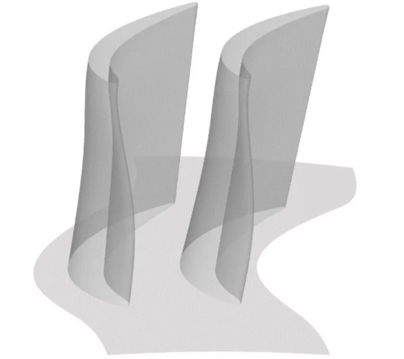
Fig.1 Turbine Blade Model
The inlet of the computational domain is placed at about 1.5axial chord from the leading edge while the outlet is located at 2 times the axial chord from the trailing edge.At the inlet,a temperature and total pressure with the turbulence intensity are specified.At the outlet,outflow boundary conditions are employed.No-slip velocity boundary conditions are used for all solid walls.An uniform heat flux(1 000W/m2-K)conditions are applied along the bottom endwall and the blade surface with the shroud is insulated.The rotor blade rotation speed is 120 m/s.And the periodic boundary condition is employed at the circumferential edge. The working fluid is air.
All the calculations are carried out with the commercial code CFX.The three-dimensional incompressible Reynolds averaged Navior-Stokes equations are solved using a finite volume formulation to discretize these equations.Grid generation is done employing NUMECA autogrid 5 that produces a structured mesh.Atypical grid along the confining surfaces and also on the contoured endwall is presented in Fig 2.And the details of the blade-endwall junction are also presented in the enlarged partial views.H form of meshes are used both in the inlet zone and the outlet zone.Along the passage,the form of meshes is O4H,in order to obtain fine mesh quality.The boundary layer meshes are also used along the junction of blade and endwall,as well as the blade surface.SST turbulence model is applied Advection term in the conservation equation and turbulent transport equation are second-order difference scheme of CFX.In all the simulations,theY+values of the first grid point away from the wall are maintained below 2.0.

Fig.2 Mesh Details
Grid independence is carried out by comparing solutions of cylinder endwall using four different meshes having 1000000,150000,2 000000and300000cells.For all cases,the grid is clustered near the bottom end wall and blade surfaces.Though the number of grid points is increased in the whole domain,the bottom end-wall and blade wall regions are refined the most.They+value for the coarse and fine grids near the bottom end wall are 1.94,1.63,1.07 and 1.04,respectively,while keeping the corresponding values on the blade wall below the permissible limits(y+≈1 for fine mesh).Fig.3 shows the span wise variation of the relative total pressure coefficient at the outlet surface.There is no significant difference for 2 000 000 and 3 000 000 cells.Therefore,calculations with 2 000 000 cells appear to be grid independent.
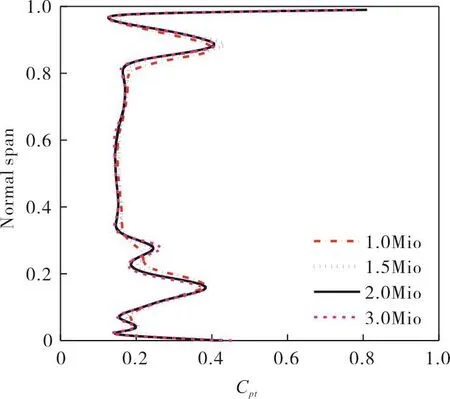
Fig.3 Distribution of Relative Total Pressure Coefficients
3 Endwall Parameterization
The profile shape of the endwall is defined by using shape function. Simple shape functions, such as sinusoidal curve,imply a preconceived notion of what the resulting geometry should look like,but the allowable design space is limited to these shapes.More complicated shape functions,such as those involving Fourier components,allow more intricate geometries to be defined,but the relationship between the input parameters and the contoured geometry become less clear.Thus,in this paper,non-uniform rational B-spline(NURB)surface is adopted to represent endwall contour because of the large design space and clear relationship between the input parameters and the endwall geometries.
NURBS surface is a bivariate piecewise rational function withporders inudirection andqorders invdirection:

Pi,jis represent of the control point,and the number of points are(m+1)and(n+1)inuandvdirection respectively.{Wi,j}is a weight factor,{Ni,p(u)}and{Nj,q(v)}are the basic functions of non-rational B spline based on the vector U and V.

The contour shape of the endwall can be modulated by adjustingWi,andPi.
The splines are controlled by a matrix of control points distributed along the endwall of interest within a given upstream and downstream limit,as shown in Fig 4.In order to guarantee the periodic boundary condition,the camber line of adjacent blades is defined as the boundary.The inlet and outlet are placed at 0.5 axial chord from the leading edge and trailing edge.Thus,the endwall surface is controlled by 11×7 points,and actually,NURB surface representing endwall contour is constructed by 25 node points,as shown in red points in Fig 4.Each control point is given a certain variation range only normal to the endwall with intentions as indicated in available open literature to avoid an unreasonable design.The non-axisymmetric endwall contourSis the superposition of cylinder endwallS0and the radial variation∆Z(u,v).Asense of the contour shape can be obtained simply through inspection of the control point values,and one can make quick changes to the contour by defining different values of ∆Z.
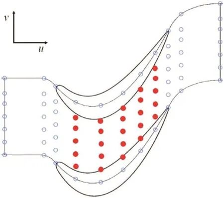
Fig.4 Distribution of Control Points
4 Design of Non-axisymmetric Endwall
Profiling of the endwall is done in such a way to have convex curvature in the pressure side and concave curvature on the suction side. From the open literatures, and the static pressure distribution on the flap endwall, shown in figure 5, three design guidelines can be obtained:(1)the radial variations in the passages are limited in 10%of the blade height,both in the pressure side and the suction side;(2)close to the leading edge,the maximum amplitude in the pressure side is 6%of the blade height;(3)near the trailing edge,the suction side allows±3%of blade height variations.
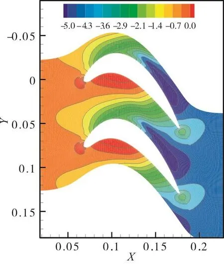
Fig.5 Static Pressure Contour on the Flap Endwall
For the designing process,there are too many solutions to be chosen and the design of experimental methodology(DOE)is used to search for the optimal endwall design.In this paper,the Optimal Latin Hypercube Design is adopted for its good space filling and balance characteristics.Design space of 40 knowledge-based samples is organized by the rule of hypercube sampling through varying each node radial coordinate.Then the numerical analysis is carried out to obtain the relationship between design parameter and the objective.In generally,the loss coefficient of total pressure and kinetic energy of the secondary flow are regarded as objective functions.The secondary velocity is defined based on the circumferentially-averaged velocity in the middle span surface,which is not affected by the secondary flow.
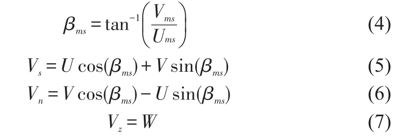
Where,U,V,Wrespectively is thex,y,zaxis component of velocity in the cartesian coordinates system and the secondary kinetic energy(SKE)is defined byVnandVz.So,

The result of the 40 candidates is presented in Figure 6.Compared to cylinder endwall,the secondary kinetic energy is reduced by 4.55%and the relative total pressure coefficients is reduced by 1.51%among the 40 designs.And the best one is NAEW15.
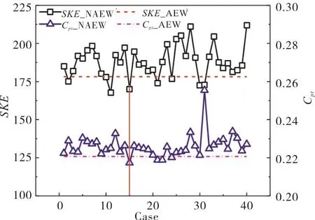
Fig.6 Results of 40 Candidates
In order to analyze the influence of factors on response better,a sensitivity analysis is carried out among all results of DOE while the objection is the minimum values of average secondary kinetic energy at the outlet surface,by using the software Isight.25 control points are taken into consideration and the sensitivity of all the factors in percentage is illuminated in Fig 7.The factors,whose sensitivity is larger than 4%,is chosen for next round of design.

Fig.7 Sensitivity of All Factors on SKE
Table 1.shows the factors and the levels in the final design.And the result is presented in Figure 8.Compared to the cylindrical endwall in the secondary kinetic energy and relative total pressure coefficients,it can be found that all the results are better except NAEW42 and NAEW54.The area averaged secondary kinetic energy is reduced by 5.48%and relative total pressure coefficients is reduced by 1.63%.Thus,the best design is obtained after iterations, as shown in Figure 9.
The contour generally consisted of a depression near the suction side and a peak near the pressure side.And the highest point on the endwall is approximately 0.05 of blade span above the cylinder endwall height while the lowest point is approximately 0.09 of blade span below the cylinder endwall.There is a peak approximately 2mm near pressure side trailing edge.
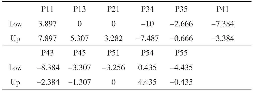
Tab.1 Final Design Factors and Level Range

Fig.8 Results of the Final Iteration
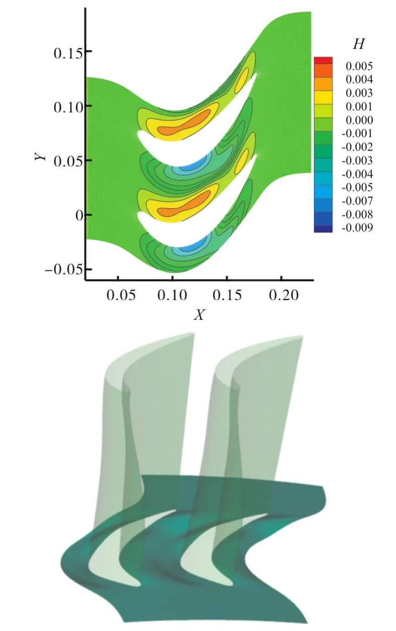
Fig.9 Geometric Parameter and Shape for Non-axisymmetric Endwall
5 Results and Discussion
Comparison of the mass flow rate of the rotor blade with and without non-axisymmetric endwall is carried out.The results show that the mass flow rate of the non-axisymmetric endwall is 1.754 5kg/s, and the mass flow rate of the flat endwall is 1.748 9 kg/s.It implies that the difference of the mass flow rate is about 0.32%,and it can be seemed as no change.Figure10 shows the radial distribution of circumferential averaged relative total pressure coefficients at blade outlet.There is a peak loss zone approximately at Normal span=0.2 near blade outlet with the influence of passage vortex and the peak value represents intensity of passage vortex.Apparently,the peak value is reduced by 11.9%from 0.47 to 0.42 because of application of optimized contoured endwall.At the same time,the total pressure coefficient(Cpt)is lower than cylinder endwall at the position of 0.05~0.5 blade span.While the loss has a little increase near endwall,which demonstrates nonaxisymmetric endwall can accelerate the fluid mixture and disturbance near endwall.
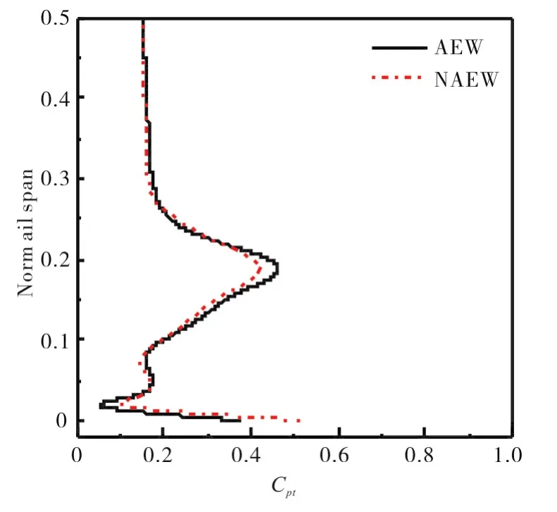
Fig.10 Radial distribution of pitch wise averaged total pressure coefficients
Blade static pressure coefficients at 5%span is shown in Figure11.At the range fromx/cax=0.3 to 0.7,blade static pressure coefficients decrease apparently,while static pressure on suction side almost no changes. Cross pressure in passage is reduced and this will inhibit the development of secondary flow.As we can see in Fig 11,static pressure of the pressure side at 20%span is decreased slightly and there is almost no change on suction side. Cross pressure is also diminished.
Figure 12.shows the contours of endwall static pressure.The black contour lines denote the iso-pressure levels. For cylinder endwall, high static pressure zone appears in the pressure side and low static pressure zone appears in the suction side.The large pressure difference leads the secondary vortex system generated from the leading edge,immediately to move toward the suction side,which causes a bigger secondary flow loss in the whole passage.After using the non-axisymmetric endwall,a high value of difference of static pressure zone appear in the suction side,which reduces the pressure difference between the pressure surface and the suction surface.The loss of the secondary flow decrease as well.
Figure 13 shows the main vortex structure of the secondary flow. When an endwall boundary layer approaches a row of turbine airfoils,it will be separated by the cross-stream-dis-crete adverse pressure gradient imparted by each airfoil and reorganized into a horseshoe vortex. The leg of the horseshoe vortex adjacent to the pressure side of the airfoil,often referred to as the pressure-side leg, entrains a majority of the low-momentum,high-vorticity endwall boundary layer fluid and subsequently grows to form the passage vortex(PV)inx/Cax=0.4,a dominant loss core in the endwall region. From the comparison in different sites, the non-axisymmetric endwall can decrease the cross pressure difference and weak the strength of the vortex.
As showed in Figure 14 both the strength of horseshoe vortex and passage vortex and the secondary flow loss are decreased.
Figure 15 shows the contours of secondary kinetic energy at outlet.There are high secondary kinetic energy zones near hub and shroud by the effect of passage vortex.Compared with cylinder endwall,there is almost no change near shroud while secondary kinetic energy peak is reduced near hub,which is demonstrated that the strength of passage vortex core region is weakened.At the same time,SKE is also reduced on the right of periodic passage.While SKE is increased slightly near hub.This also demonstrates nonaxisymmetric endwall increase the loss and disturbance near endwall too.
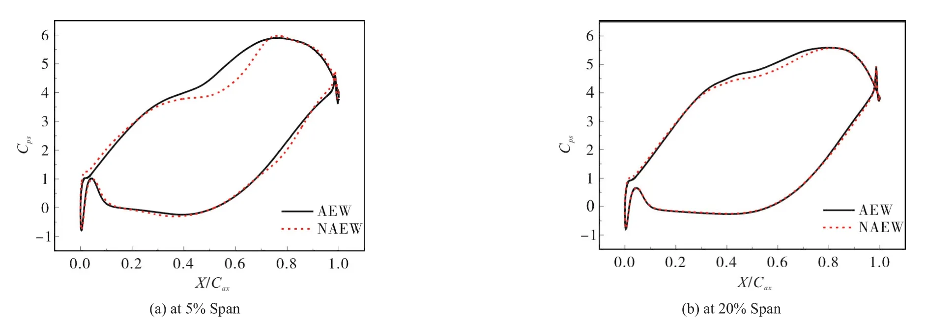
Fig.11 Blade Static Pressure Distribution

Fig.12 Static Pressure Contour at the Endwall Surface

Fig.13 Vortex Structure of the Secondary Flow

Fig.14 The Strength of the Vortex
Figure 16 shows the contour of endwall stanton number.The black contour lines denote the iso-pressure levels.For cylinder endwall,high heat transfer zone extends from leading edge pressure side to passage with the effect of horseshoe vortex.This demonstrates contoured endwall weakens the intensity of horseshoe vortex.As mall high heat transfer zone appears near pressure side in the forward portion of the passage.There is a little decrease in the forward portion of passage and apparently increase in the aft portion of passage.At the same time,the heat transfer in trailing edge zone is increased.To make its difference more clearly,the Stanton map of contoured endwall is deducted from the asymmetric and is presented in Figure 16(c).Except blue regions indicating enhanced heat transfer,central channel displays reduction of heat transfer on the path of passage vortex.
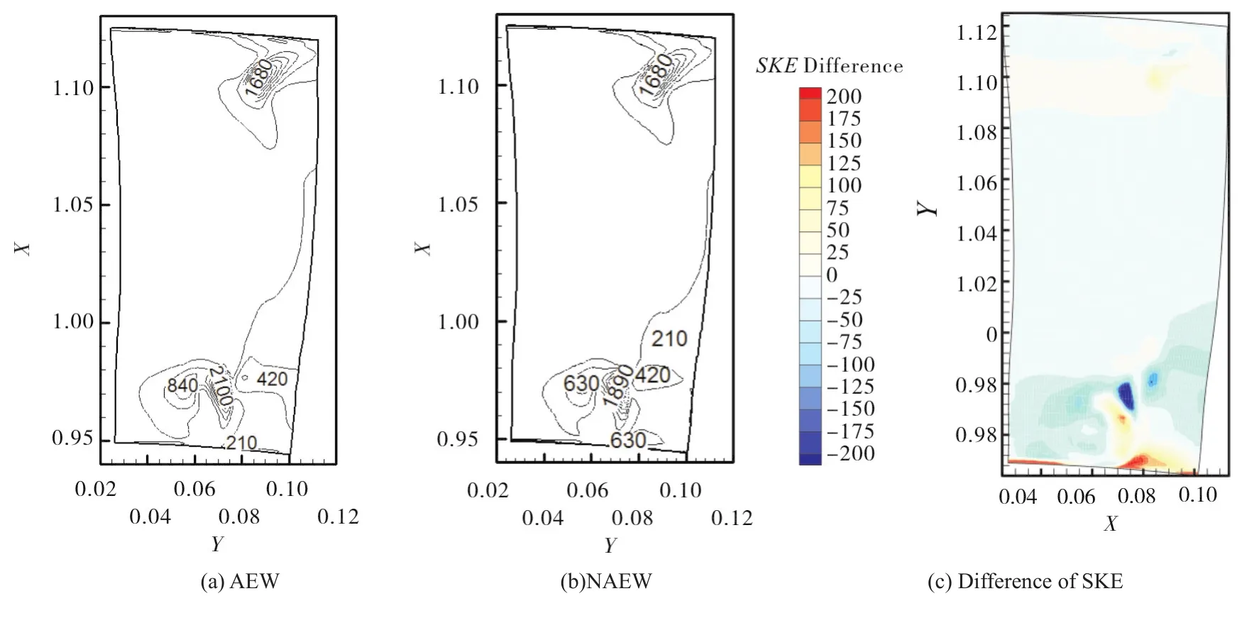
Fig.15 SKE Contour at Exit Surface

Fig.16 Stanton Number Contour on Endwall
6 Conclusions
The non-axisymmetric endwall is parameterized by the method of NURBS and the optimized non-axisymmetric endwall is obtained.The optimized contoured endwall is regard as research objects to study the influence of non-axisymmetric endwall on endwall flow and heat transfer. The results show the secondary kinetic energy is reduced by 5.48%and the relative total pressure coefficients is reduced by 1.63%at the exit surface for the contoured endwall.
1)Non-axisymmetric endwall can decrease the cross pressure by adjust static pressure contour and weaken the horseshoe vortex and passage vortex.
2)Non-axisymmetric endwall can reduce the secondary kinetic energy and total pressure loss though the flow performance near endwall is not improved.
3)Effective non-axisymmetric endwall can improve the endwall heat transfer performance locally.As mall zone of high heat transfer appears near pressure side in the forward portion of the passage.Heat transfer is slightly decreased in the forward portion of passage while increased in the aft portion of passage.At the same time,the Stanton number near the trailing edge is increased.
7 Acknowledgments
The first author is grateful for financial support from the Chinese National Nature Science Funds(No.51276116)and Shanghai Electric Gas Turbine Company.The authors are also thankful for useful discussions with Mr. Jian.Zhang.
