Stable grasping gesture analysis of a cable-driven underactuated robotic hand
2018-10-17XinQiaoShanglingHuangYongLiuRongqiang
Lü Xin Qiao Shangling Huang Yong Liu Rongqiang
(School of Mechatronics Engineering, Harbin Institute of Technology, Harbin 150001, China)
Abstract:The stable grasping gesture of a novel cable-driven robotic hand is analyzed. The robotic hand is underactuated, using tendon-pulley transmission and a parallel four-linkage mechanism to realize grasp. The structure design and a basic grasping strategy of one finger was introduced. According to the established round object enveloping grasp model, the relationship between the contacting and driving forces in a finger and stable grasping conditions were expounded. A method of interpolation and iteration was proposed to obtain the stable grasping gesture of the cable-driven hand grasping a round target. Quasi-statics analysis in ADAMS validated the variation of grasping forces, which illustrated the feasibility and validity of the proposed analytical method. Three basic types of grasping gestures of the underactuated hand were obtained on the basis of the relationship between the contact forces and position of a grasped object.
Keywords:grasp gesture; tendon-pulley transmission; underactuated; grasp force
With the increase in human space missions and deep space explorations, an increased number of spacecrafts are developed and launched into deep space. Generally, the average working life of those spacecrafts is five to eight years.The number of geostationary satellites that lose their efficacy will maintain their swift growth[1]. The scrapped spacecrafts become space trash, which seriously affects the safety of other working spacecrafts and astronauts. The service life of a scrapped spacecraft can be considerably extended if the spacecraft can be maintained on-orbit before being scrapped, such as by replacement of damaged components and additional energy. A highly reliable and active capture mechanism is required for either on-orbit spacecraft maintenance and servicing or recycling space trash. Compared with conventional robotic hands, underactuated manipulators are superior in saving energy, light-weight, and have enhanced flexibility of the system.
The principle of underactuation has been applied to the design of robotic hands since the 1970s[2], and many famous underactuated robotic hands have been developed. The existing underactuated robotic hands can be sorted into three different types in terms of transmission, namely linkages, gears, and tendons. SARAH is a typical example of a double-stage linkage transmission[3]. The robotic hand has 3 fingers, a total of 10 degrees of freedom (DOFs), and 2 drive motors. Closing and opening the finger take place through the transmission of a double-stage mechanism. Under the springs and mechanical limits set on every joint of the fingers, the fingers can grasp polyhedrons, cylinders, and other irregular objects with a high degree of adaptability[4]. Besides, many kinds of linkage underactuated hands are developed based on SARAH and have been used in agriculture[5]and other industries[6]. Owing to the high transmission precision of the gear, the underactuated hand driven by gear linkage has been widely developed[7]. A PASA finger has two joints, which mainly comprises an actuator, an accelerative gear system, a spring, a parallel four-link mechanism, and a mechanical limit[8]. The PASA hand, developed with three PASA fingers and eight DOFs, is typical of underactuated gear linkage robotic hands. In addition, the HAG-SR[9]and the FSJ[10]are mature applications of gear-driven transmission. With the development of bionics, dexterous hands based on the characteristics of a human hand have also been developed with tendon transmission, which uses flexible cables to deliver the driving force to the joints[11-12]. Davidson et al.[13]proposed an tendon-driven apple-picking hand which adopted compliant flexure joints to improve system performance. Nacy et al.[14]proposed the artificial hand mechanism, which was composed of three fingers; each finger had one degree of freedom and was actuated by the pulleys-tendon mechanism with flexible elements. The fingers will bend inward when a driving force is applied to the rope and recover when the driving force disappears. Tan et al.[15]designed a humanoid robotic hand TH-3R, which had five fingers and each finger was able to self-adaptively grasp a variety of objects. Based on the tendon-driven mechanism, Liu et al.[16]designed the HIT prosthetic hand, which is composed of five independent fingers. Except the thumb finger, each finger was actuated by one DC motor by using tendon transmission. Carbone et al.[17]proposed the FEDERICA hand, which used tendons and pulleys to drive all phalanxes while requiring a single actuator for the whole hand. The columbia hand is a highly underactuated hand containing three fingers, in which each finger has 3-DOF and is driven by only two actuators[18]. The DARPA ARM-H hand is comprised of four identical fingers that are connected to the main driver board located inside the palm unit. Brakes are used to make the fingers move in order[19].
In this paper, a type of underactuated hand, composed of two symmetrical fingers, is introduced. It is an underactuated finger using tendon-pulley transmission and parallel four-linkage mechanism to realize grasping function. Due to the deployable, modular and lightweight characteristics, the underactuated mechanism will be used in space capture in the future. Compared with a full-actuated hand, self-adaptive grasp is a highlighted feature in an underactuated hand. In order to study the stable grasp gesture, a model of grasping round objects similar to an enveloping grasp is established. Grasp forces and the corresponding stable grasping gesture are analyzed using iterative calculation.
1 System Design
When grasping an object, the human hand can envelop the object with its fingers and palm or grasp using the tips of two fingers. Fingertip pinching is suitable for capturing small objects and is dexterous in operation. Meanwhile, envelope grasping is suitable for large volume targets and has a high stability. The space capture hand targets large spacecraft while the grasp requires a high level of stability. Hence, the envelope grasp is selected as the capture strategy.
1.1 Working principle
The underactuated finger is composed of three phalanges, as shown in Fig.1. Each phalange is simplified into a parallelogram truss structure and the ropes connect the diagonals. By pulling one rope, the phalange unit has an instantaneous translation motion. Three knuckles are the root phalange (RP), the middle phalange (MP) and the distal phalange (DP).
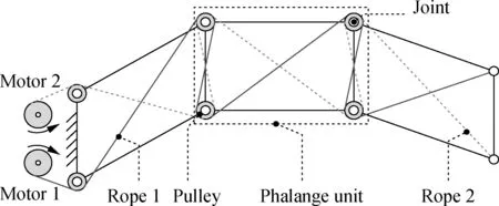
Fig.1 Schematic of an underactuated finger
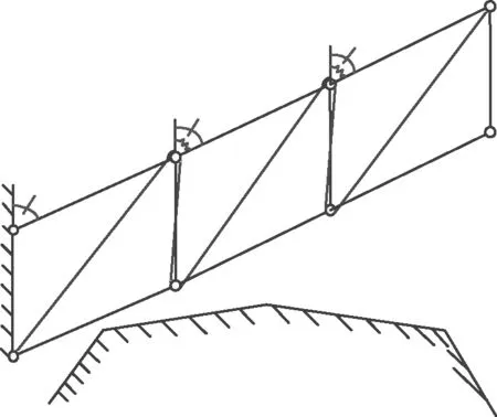
Each rope crosses through the serial knuckles in a Z-shaped route. Several deflecting pulleys are installed on joints.The passive elements such as springs and joint frictions are useful for keeping the finger from incoherent motion. Fig.2 shows a basic grasping strategy. First, the entire finger moves from the initial state to the RP in contact with an object. Then, the RP stops moving while the MP continues to move towards the object until it contacts the object. The MP stops moving when it touches the object. However, the DP continues to move until it touches the object. In contrast, the releasing process is realized by a reverse driving motor.
(a)(b)

(c)(c)Fig.2 One grasping strategy of the finger. (a) Initial state; (b) RP making contact with object; (c) MP making contact with object; (d) DP making contact with object
1.2 Structure design
Fig.3 illustrates the structure of a single finger. The finger is arranged on the bottom plate which is consistent with the schematics. Ropes 1 and 2 bypass the pulleys at the joints with one end fixed on the DP whereas the other end is connected to the motors. The stable grasp gesture is examined in the present study. Therefore, the passive elements are not included in the research. Fig.4 demon-strates the structure of the mechanical hand, in which two fingers are envelope-grasping a circular object.

Fig.3 Diagram structure of one finger
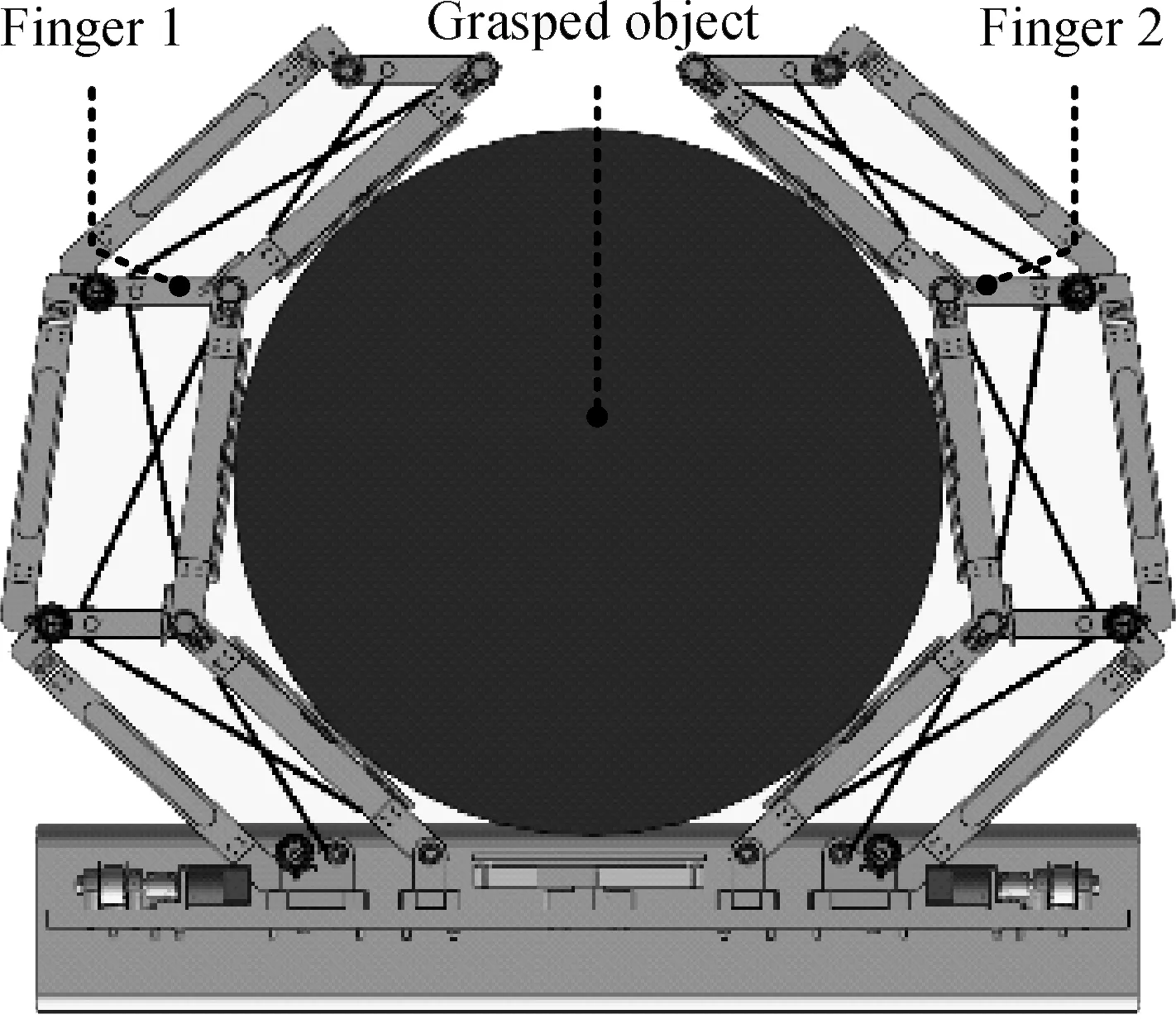
Fig.4 Robotic hand enveloping object
2 Static Analysis of Grasp
2.1 General grasping force of a finger
The static analysis results are consistent due to the identical structures of the fingers on both sides. This section analyzes and presents the left finger. The grasp is accomplished when the driving and contact forces maintain balance. Fig.5 presents a force analysis of the finger.
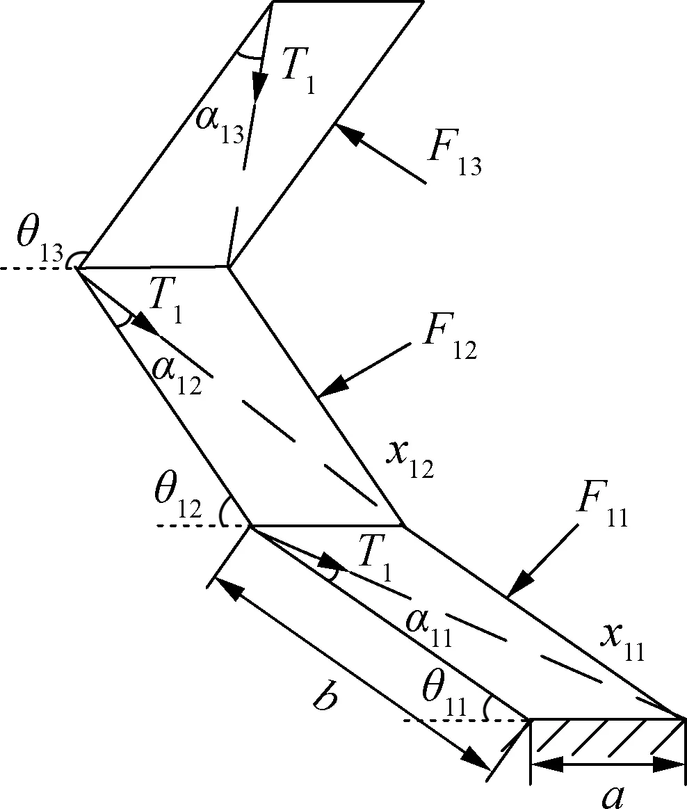
Fig.5 Illustration of forces on the left finger
A few hypotheses are presented to simplify the calculations. First, assuming that no friction exists on the fingers. Secondly, mass inertia effects are ignored due to quasi-static analysis. Thirdly, assuming that the object is fixed in space in terms of analyzing the force on a single finger. The grasping force is established using vector mechanics and the principle of the virtual work in Ref.[20]. The relationship among driving force, equivalent torques on joints and grasping forces is as follows:

(1)
2.2 Static analysis of grasped object
The grasped object is in a static balance condition under the action of the left and right fingers, as shown in Fig.6. When the grasp is stable, based on the force-closure grasping theory, we have
(2)
In addition, the finger is in a state of static balance even if all phalanges are not grasping the object due to its
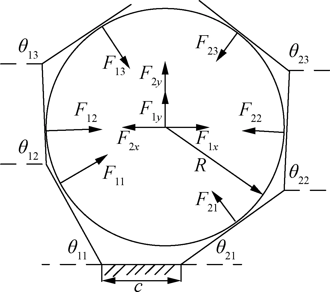
Fig.6 Analysis of the grasping forces exerted on object
self-adaptive capability. Hence, the grasping force should satisfy the conditions in Eqs.(1) and (2). Eq.(2) is changed into two components, namely, horizontal and vertical, as follows:
(3)
With regard to the grasped object, the stable condition is that in which the resultant forces in the horizontal and vertical directions are zero,
(4)
3 Analysis and Simulation of Grasping Process
The grasping process contains two stages, the envelope stage and the stable stage. In the envelope stage, the three phalanges successively close on the object until they touch the object. When the three phalanges touch the object, the underactuated hand will move into its own balanced and stable posture. Meanwhile, the hand has to adapt to the contour of the object. Finally, the fingers and the object achieve balance and become stable.
3.1 Envelope grasp and grasping force calculation
In the envelope stage, the outline of the contact phalange is always tangent to the enveloping cover of the grasped object. The joint positions and locations of contact point coordinates are obtained based on the D-H method. Fig.7 shows the generalized joint coordinate system. The midpoint of the palm is the coordinate origin of the fixed coordinate. The generalized joint coordinate system set up in the left hand is taken as an example.
The relationship between two adjacent coordinate systems is obtained through the coordinate changing method.
(5)
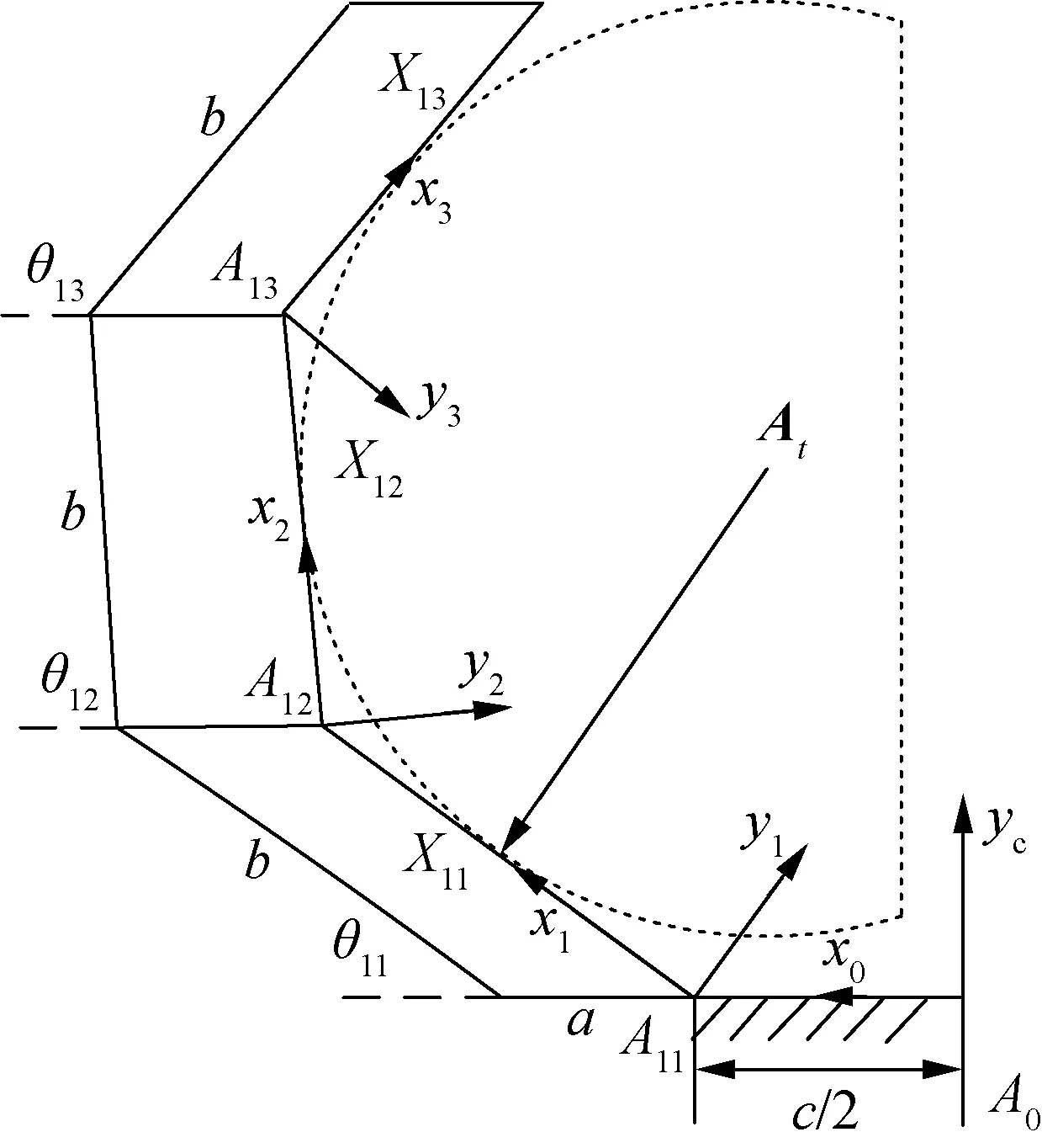
Fig.7 Joint coordinate system of the left finger
(6)
Hence, the transformation matrix for each phalange coordinate relative to the base coordinate {A0} is obtained.
(7)

(8)
The location of jointA1mis

(9)
The vector from the center of the round grasped objectAt=[-xt,yt]Tto the contact point is
(10)
The vector from jointA1nto the contact pointX1nis expressed as
(11)
According to the geometric tangent relationship between knuckles and the grasped object, we have
AtX1n·A1nX1n=0, |AtX1n|=R
(12)
Using Eq.(12), the contact point positionx1nand joint angleθ1nare obtained. Similarly, the contact point positionx2nand joint angleθ2nin the right finger are obtained using the same method and the process will not be repeated. All contact point positions and joint angles are brought into Eq.(1) to obtain the grasping forces.
Owing to the symmetry of two fingers, the enveloping characteristics of the right finger are similar to those in the left finger. Hence, the grasping forces and contact position of the two fingers are obtained by analyzing the condition of a single finger enveloping an object in the positions ofxtranging from -150 to 150 mm,yt=400 mm. Tab.1 presents the set of parameters while Fig.8 shows the changes in joint angles and contact forces on the three phalanges.

Tab.1 Parameters of cable-bar units
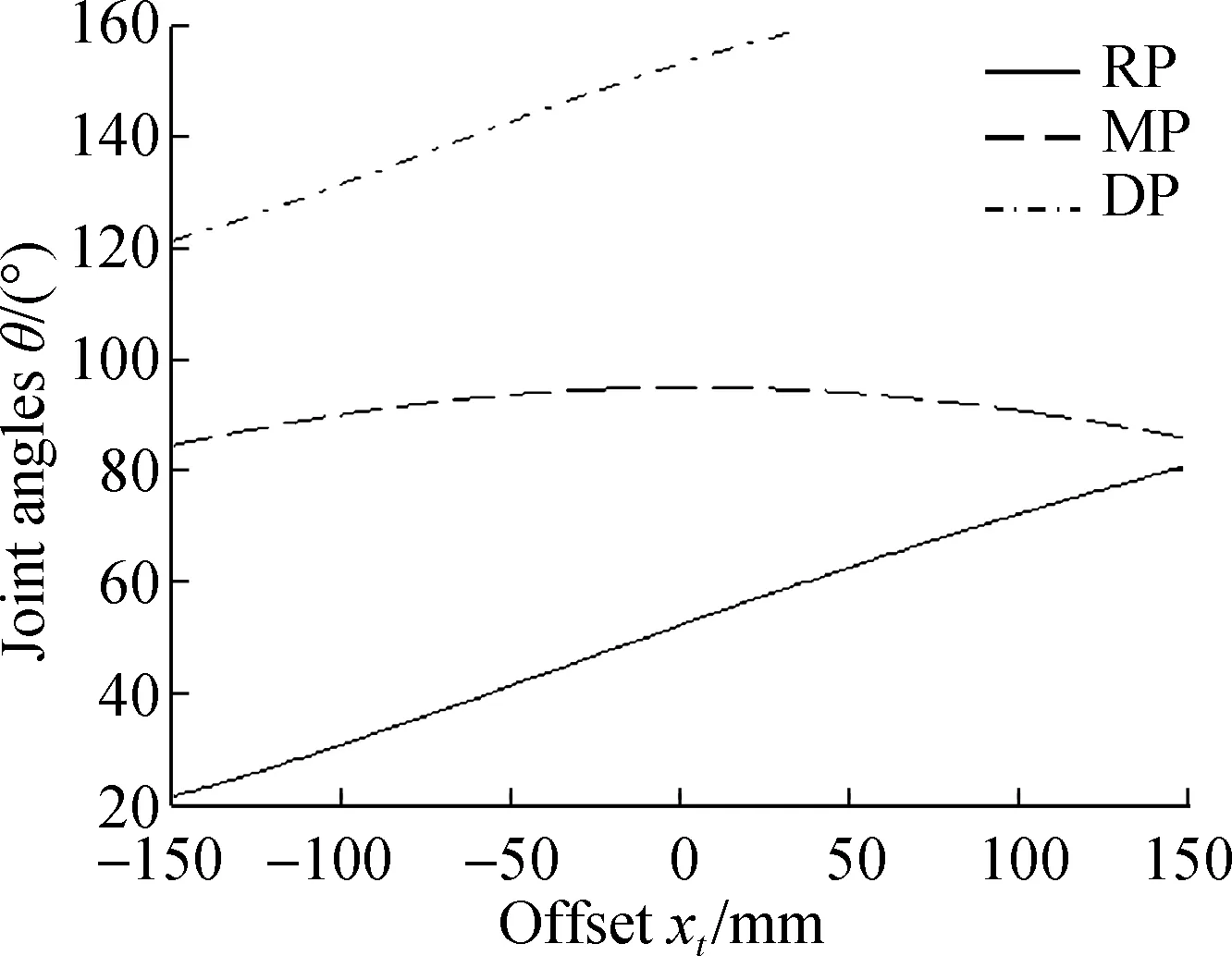

(b)Fig.8 Curves of forces and angles of envelopment gesture. (a) Joint angles at different positions;(b) Contact forces at different positions
3.2 Analysis of steady grasp posture and grasping force
Fig.8 shows that there are negative contact forces in the finger envelope process. This phenomenon does not occur in real grasping missions since only an elastic contact force occurs between the object and the phalanges. The contact force can only be greater than or equal to zero. Then, negative contact forces do not constitute a steady grasp posture.
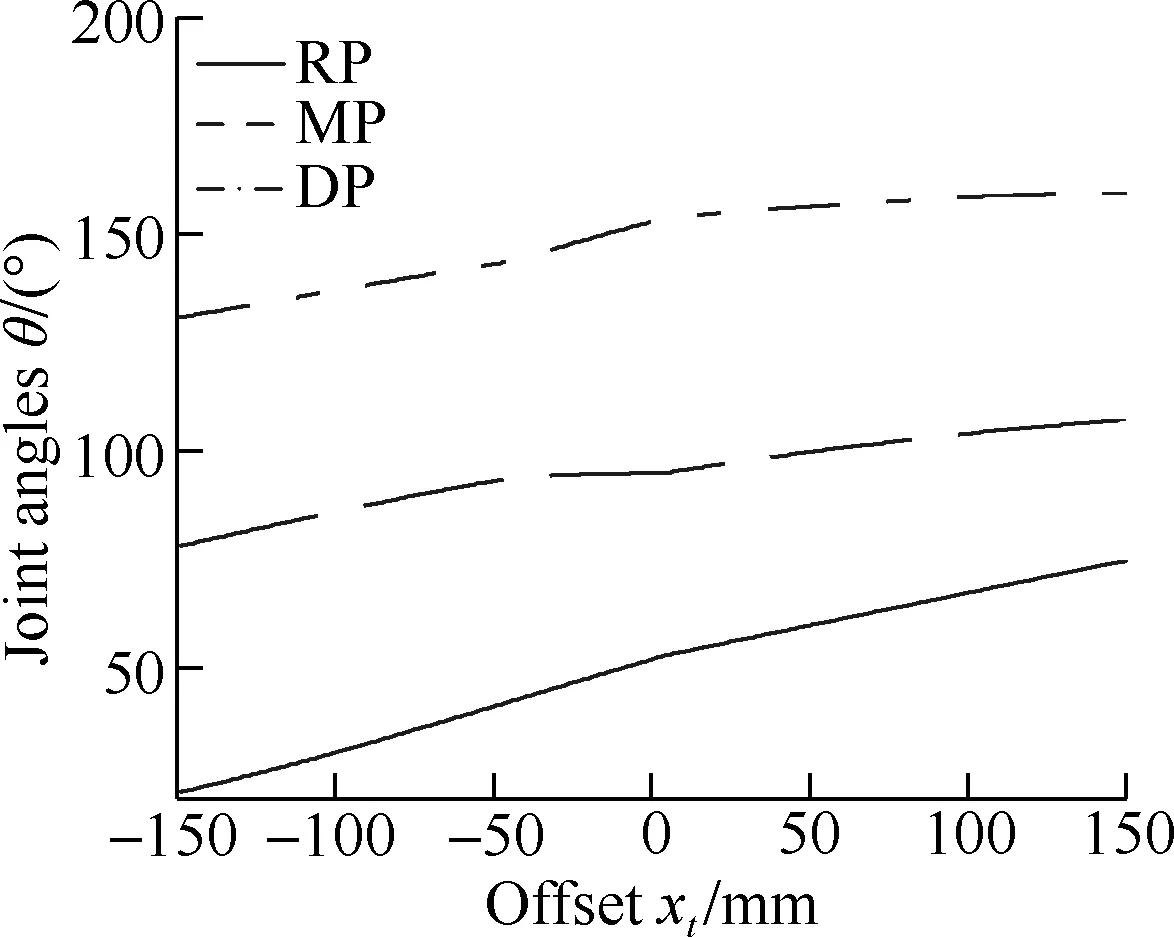
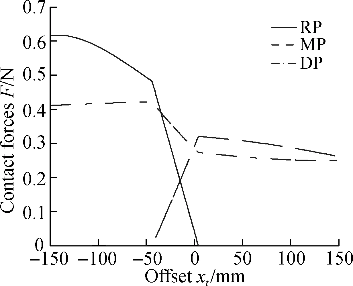
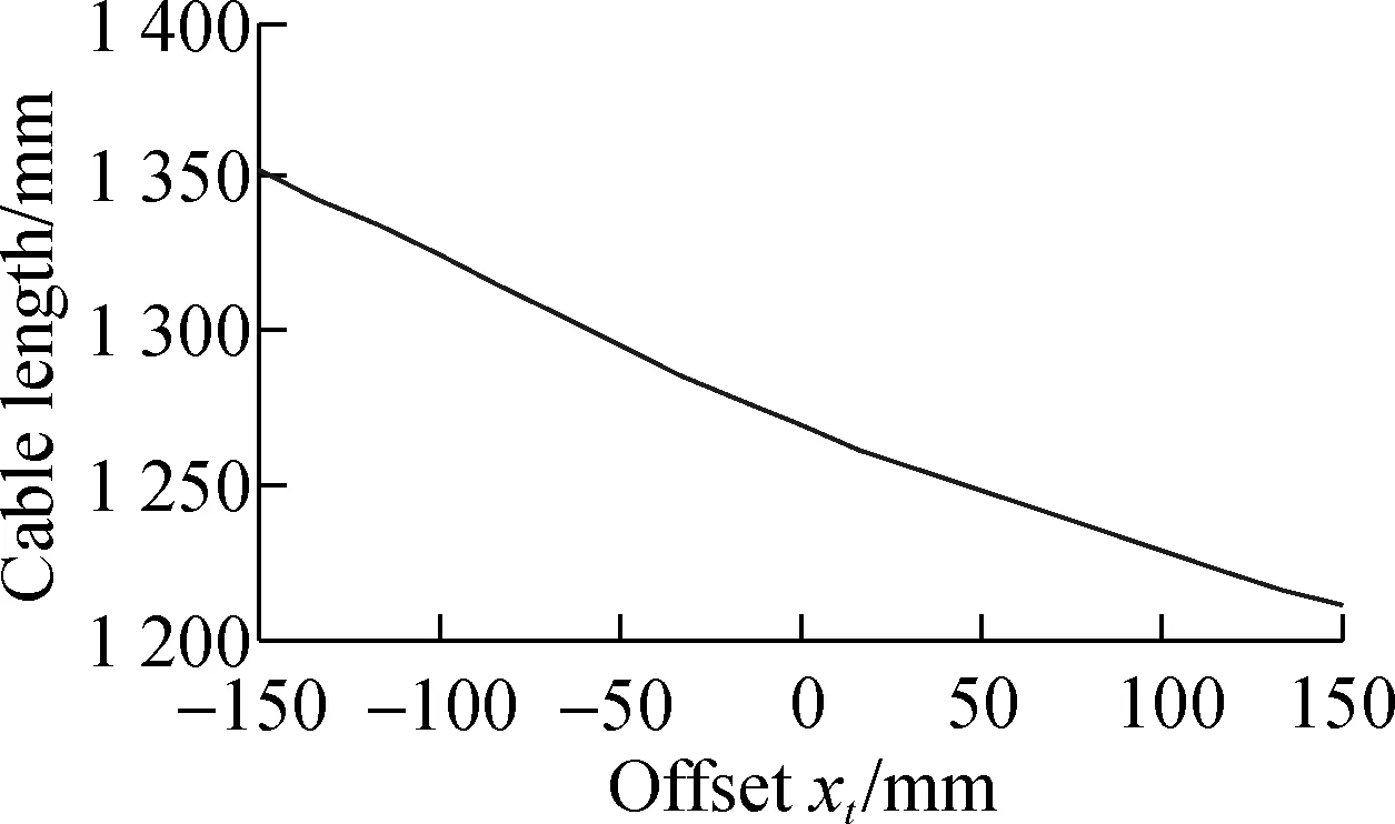
We used a method of interpolation and iteration in Matlab to obtain the stable grasp posture. The contact force is calculated when a phalange turns to a small angle. If the contact force is negative, then the phalange will continue to turn within the same small angle, and the contact force will be computed again until the structure stabilizes. Furthermore, the contact point will disappear if the phalange is not in contact with the object. It needs to assume that the contact point still exists and the position does not change during the process. Fig.9 demonstrates that the joint angles and contact forces are in a steady state after grasping the object in different positions.
(a)
(b)
(c)

(d)Fig.9 Curves of forces and angles of stable gesture. (a) Joint angles at different positions;(b) Contact forces at different positions;(c) Cable length in the finger; (d) Cable length in the phalanx
As previously mentioned,Fig.9(b) shows the contact force distributions of the left finger. The contact forces of the left finger in the range of 0 to 150 mm represent the contact forces of the right finger in the range of -150 to 0 mm due to the symmetry. If the contact force is zero, then the phalange separates from the object.
Take the area ofxtranging from 0 to 150 mm as an example. This area can be divided into three parts using the number of the contacted phalanges. In the area ofxtranging from 0 to 4 mm, three positive contact forces exist on the phalanges of the left finger. All three phalanges are in contact with the object. In the area ofxtranging from 4 to 150 mm, the contact force on the root phalange of the left finger is 0. Hence, the root phalange of the left finger separates from the object. According to the distribution of contact forces in the area ofxtranging from -150 to 0 mm and the symmetry of the two fingers, three positive contact forces exist on phalanges of the right finger in the area ofxtranging from 0 to 44 mm. In addition, the contact force on the middle phalange of the right finger is 0 in the area ofxtranging from 44 to 150 mm.
Hence, three basic steady grasp postures of the underactuated hand are obtained as shown in Fig.10. Inxt=[0,4), six contact points are in contact with the object on the hand. Meanwhile, inxt=[4,44), five contact points are in contact with the object on the hand. Inxt=[44,150], four contact points are in contact with the object on the hand.

(a)(b)

(c)Fig.10 Stable gesture changing with the position. (a) Six points;(b) Five points;(c) Four points
3.3 Balance force analysis of grasped object
The resultant forces in the horizontal and vertical directions on the object from the two fingers can be calculated using Eq.(3) and the results in Fig.9(b). Eq.(1) shows that the contact forces have a linear relationship with the driving force on one finger. Hence, Eq.(4) can be realized by adjusting the driving forces on the two ropes.
Owing to the coupling relationship between the horizontal and vertical directions of the contact forces, the calculation is not conducive if both directions simultaneously change. Hence, let the object maintain balance in the horizontal direction first, and then the driving forceT2on the right finger can be obtained. Parameterηis introduced to explain the ratio of tensions on the left and right ropes; hence,η=T1/T2. Fig.11 shows the relationship between two driving forces to maintain object balance in the horizontal direction.

Fig.11 Ratio between forces on two ropes
Based on the condition of maintaining balance in the horizontal direction first, the resultant forces in the vertical direction can be calculated as shown in Fig.12. Inxt=[0,38), the resultant forces in the vertical direction are less than zero, which means that the object has a tendency to move inside the hand. By contrast, the object has a tendency to move outside the hand inxt=(38,150]. (xt,yt)=(38, 400) is the balance point, where the object and hand are completely stable with six phalanges in contact with the object.
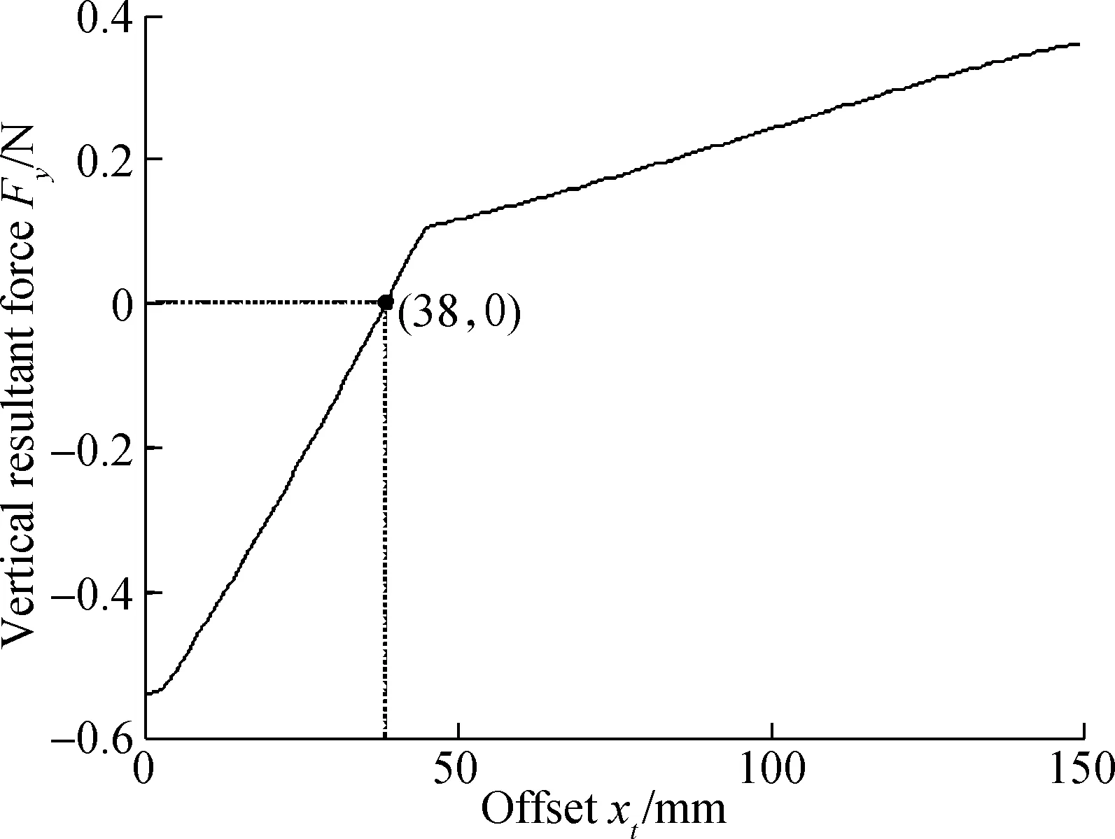
Fig.12 Resultant force in vertical direction
Moreover, the initial vertical space of the three phalanges which envelops a circle with a radius of 380 mm isyt=[380,440]. Hence, taking the preceding phalanges mentioned as an example, the center of the enveloping space is in the intervalxt=[0,150],yt=[380,440]. Setting the sampling offsetytevery 5 mm, the balance points can be obtained in different vertical positionsyt, as shown in Fig.13. Area Ⅰ is the stable area of the grasping object with three phalanges. In area Ⅱ, the vertical grasping forceFyis less than zero. The object has a tendency to move inside the hand. In area Ⅲ, the vertical grasping forceFyis more than zero. Hence, the object has a tendency to move outside the hand. Finally, the center of the target falls on the stable grasping curve to achieve stability.

Fig.13 Curves of stable grasping position in two-dimensional space
4 Stable Grasp Simulation in ADAMS
ADAMS modeling and simulation are used to verify the calculation accuracy of the stability and grip force program of the preceding analysis mentioned. All the parameters in the ADAMS model are set in keeping with the previously mentioned values.
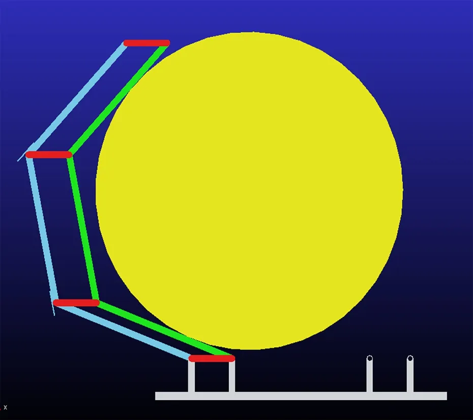
The movement of the grasped object is a horizontal linext=[-150, 150],yt=400. Fig.14 presents the entire grasping process of a finger. From the moving process in the simulation, three changes occur in the form of grasping. Fig.14(a) shows that the RP and DP come into contact with the object. All three phalanges are in contact with object as shown in Fig.14(b). Furthermore, the MP and DP are in contact with the object as shown in Fig.14(c). In grasping forms, the grasping process in ADAMS is consistent with the theoretical analysis in Section 3.2. Hence, three basic grasping forms occur for a hand grasping a moving object fromxt=0 toxt=150. The three grasping forms are consistent with the forms shown in Fig.10.
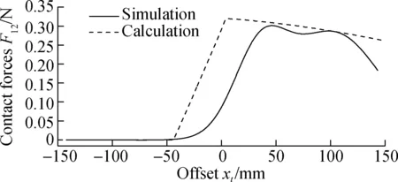
Compared with the theoretical results calculated in Matlab, simulation results and curve tendencies are consistent with the theoretical results. Figs.15 shows the simulation results.
The movement coupling will appear due to the self-adaptive capacity of the underactuated finger. Hence, a chattering phenomenon will occur when a certain phalange comes into contact with an object. The simulation results have been smoothed to demonstrate a clear curve. However, smooth processing leads to a certain deviation. In contrast to the simulation and theoretical results, the simulation curve translates to the right side compared with the theoretical curve although the tendency is basically the same. This phenomenon can be attributed to the width of the bar. In the theoretical analysis, the bar is considered ideal and its width is ignored. However, the width of the bar is 25 mm in the simulation. The width is also a factor that affects the distribution of the grasping force. Therefore, the simulation curve translates to the right.
(a)(b)
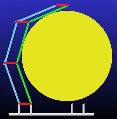
(c)Fig.14 Grasping process of a finger in simulation. (a) RP and DP contact object; (b) All phalanges contact object; (c) MP and DP contact object

(a)
(b)
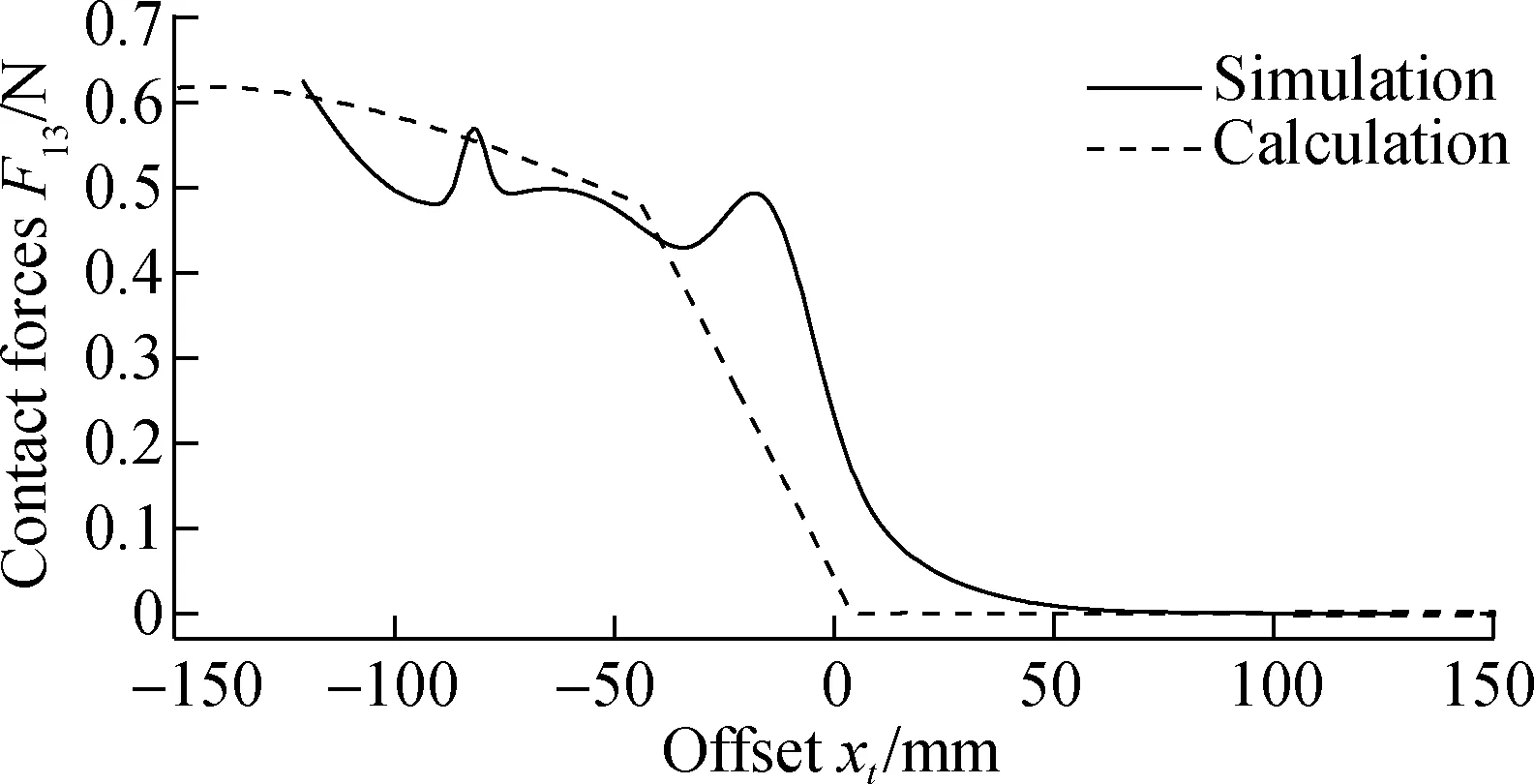
(c)Fig.15 Simulation results of force on joints. (a) On the end joint; (b) On the middle joint; (c) On the root joint
5 Conclusion
The stable grasping area of an underactuated robotic hand driven by cables is analyzed in this paper. First, the envelope grasping model is established. The relationship between the contacting and driving forces in a finger and stable grasping conditions are expounded. Then, taking envelope grasping of a round object with a radius of 380 mm as an example, the distributions of contact forces in the RP, MP, and DP are analyzed. A total of three basic steady grasp postures of one finger is obtained. Depending on the horizontal position of the grasped object, the grasp postures of a hand comprise six, five, and four points that come into contact with the object. Thirdly, according to the balancing analysis of the grasped objects, the relationship between two driving forces is obtained. Furthermore, stable grasping areas are obtained. Finally, all the grasping models and theoretical analyses are verified in the ADAMS simulation. Therefore, this study finds that the hand driven by cables has a good self-adaptive grasp. By adjusting the two driving forces, grasping results become multifarious.
杂志排行
Journal of Southeast University(English Edition)的其它文章
- Mathematical models for properties of mortars with admixtures and recycled fine aggregates from demolished concretes
- Damage evolution analysis of cast steel GS-20Mn5V based on modified GTN model
- Analogy-based software effort estimation using multi-objective feature selection
- A recognition model of survival situations for survivable systems
- A weighted selection combining schemefor cooperative spectrum prediction in cognitive radio networks
- Syntheses and calculation of (E)-4-chloro-4’-ethoxystilbene and (E)-4,4’-dichlorostilbene
