Damage evolution analysis of cast steel GS-20Mn5V based on modified GTN model
2018-10-17YanHuadongJinHui
Yan Huadong Jin Hui
(Jiangsu Key Laboratory of Engineering Mechanics, Southeast University, Nanjing 211189, China)(School of Civil Engineering, Southeast University, Nanjing 211189, China)
Abstract:A modified Gurson-Tvergaard-Needleman(GTN) model that accounts for the mixed (isotropic and kinematic) hardening of cast steel GS-20Mn5V was developed and implemented in the finite element program ABAQUS/Standard via a user-defined material subroutine UMAT. This model couples the stress state and damage evolution (pore volume fraction increase) by a classic method that assumes that the total void volume fraction is divided into a nucleation and a growth part. A parametric study was conducted to assess the effect of modified GTN model parameters on mechanical properties such as the nucleation, growth and coalescence of voids and to obtain the optimal parameter combination by the orthogonal test method. The predicted load-displacement curves of notched specimens with the optimal parameters are favorably compared to the experimental curves. Therefore, the modified GTN model can be used to predict the damage evaluation and fracture behavior of GS-20Mn5V.
Keywords:cast steel; Gurson-Tvergaard-Needleman(GTN) model; damage evolution; orthogonal test method; optimal parameter combination
Cast steel is an important metal material that is widely used in civil engineering applications due to its strength and ductility[1]. Unfortunately, a variety of casting defects such as porosity and cracks are usually present in the as-cast components and can lead to the degradation of mechanical properties[2]. It is difficult to eliminate the porosity by modifying the casting technology due to cost impediments. Studies have demonstrated that both micro and macroporosity will affect the mechanical properties and fatigue life of castings[3]. When a casting is completed, the workers perform a nondestructive evaluation method (NDE), such as ultrasonic testing, to find the macroporosity and repair it. However, the resolution of NDE is insufficient to determine the size and location of the microporosity. To eliminate the influence of microporosity, designers employ excessively high safety factors to ensure reliability, leading to components that are heavier than necessary[4]. Therefore, understanding the effects of porosity on the mechanical properties of the cast steel is the key to assessing final life.
In recent decades, many scholars have explored the failure mode that results from the damage evolution mechanism of microporosity[5-8]. From a physical point of view, the damage of metallic materials can be divided into three stages: void nucleation, growth and coalescence[9]. Gurson[5]proposed an approximate yield function for a finite cell model with microvoids based on the work of Rice[10]. Then, Tvergaard[6-7]considered the interaction between voids and introduced three correction parameters to make the numerical results more consistent with the experimental results. Tvergaard and Needleman[8-9]introduced a damage functionf*to consider the effect of void coalescence. Therefore, the GTN damage model, which is one of the most widely used ductile damage models, was chosen to describe the fracture of metallic materials[10-12].
1 Modified GTN Constitutive Model
1.1 GTN constitutive model
The yield condition of the GTN model takes the following form[5-9]:
(1)
whereσyis the initial yield stress of the matrix material;σeqis the effective Von Mises stress;σmis the hydrostatic stress; three arbitrary parametersq1,q2andq3are introduced by Tvergaard[6-7]to make the prediction of the Gurson equation agree with numerical results;fis the actual void volume fraction. The effective porosity volume fractionf*is introduced by Tvergaard et al.[8-9]to account for the final material failure for void coalescence, which is a function of the actual void volume fractionfand is expressed as
(2)

(3)
According to Ref.[8], the growth rate of the actual void volume fractionfis defined as the sum of the growth of existing voids and the nucleation of new voids:
df=dfgrowth+dfnucleation
(4)

(5)
In the nucleation term, the equivalent plastic strain rate dεplis the exclusive dependent variable:
dfnucleation=Adεpl
(6)
The void nucleation intensityAis a function[13]of the volume fraction of all particles with potential for microvoid nucleationfN, the mean nucleation strainεNand the corresponding standard deviationSN.
(7)
In a metallic material, the plastic flow depends on the actual void volume fractionfand the equivalent plastic strainεpl. According to the equivalent work principle, the evolution equation of equivalent plastic strain is given by[14]
(8)
1.2 The mixed hardening model
The yield surface is usually a constant of the ideal elastoplastic materials. However, the plastic deformation of the practical materials shows a more pronounced hardening effect, and the yield surface will change with the development of plastic deformation. There are three hardening models: the isotropic hardening model, the kinematic hardening model and the mixed hardening model.
The isotropic hardening model assumes that the yield surface expands uniformly under loading, while the yield surface center moves parallel to the hardening curve in the kinematic hardening model. In fact, many practical materials show a combined effect of isotropic and kinematic hardening behavior. To address this case, a mixed hardening model is introduced to address the change in the yield stress and the back stress[15-16].
The general formulation of a mixed hardening model is as follows:
φ(σij-αij)-k(κ)=0
(9)
whereσijis the Cauchy stress tensor; the back stress tensorαijis used to describe the movement of the yield surface center in the stress space; andk(κ) is used to describe the expansion of the yield surface with the increasing plastic strain.
Yield stressσis the a function of equivalent plastic strainεpl, andσdefines the evolution of the yield surface. Yield stress is expressed as an exponential equation[15]:
σ=σy+a[1-exp(-bεpl)]
(10)
whereaandbare the hardening coefficient and exponent, respectively, which can be fitted by the true stress-plastic strain curve.
Frederick and Armstrong[16]proposed a kinematic hardening model which can calculate the change in back stress,
(11)
whereCandγare material constants.
When the material is subjected to auniaxial tensile load, Eq.(11) can be expressed as
(12)
In contrast to Eqs.(10) and (12),Candγcan be obtained using the following equation:
(13)
γ=b
(14)
1.3 A modified GTN model accounting for the mixed hardening
To apply the research results to practical engineering analysis, the modified GTN constitutive relationship considers the influence of back stress and yield surface expansion on the basis of the classical GTN damage theory.
Σijis the difference between Cauchy stressσijand back stressαij:
Σij=σij-αij
(15)
The effective Von Mises stress and the hydrostatic stress can be expressed as
(16)
(17)

The yield function of the modified GTN model is given by
(18)
According to the classical numerical integration of the elastoplastic constitutive relationships[14,17], the modified GTN model can be implemented in the finite element program ABAQUS/Standard via a user-defined material subroutine UMAT.
2 Finite Element Analysis
2.1 Material mechanical testing
The material used in this study is cast steel GS-20Mn5V. It is a cast carbon steel that has both good ductility and high strength. It has the following chemical composition: C 0.17 to 0.23; Si 0.6;Mn 1.00 to 1.50; P 0.025; S 0.020; Cr 0.30; Mo 0.15; Ni 0.40. The objective of the experimental program in Ref.[18] studied the mechanical properties of cast steel GS-20Mn5V under uniaxial tensile stresses.
The dimensions of the tensile specimens (smooth and notched) are shown in Fig.1. The basic mechanical properties of GS-20Mn5V are listed in Tab.1. The load-displacement curves of the specimens with a 1 mm or 4 mm notch radius are discrete, while the load-displacement curves of the specimens with a 2 mm notch radius are in good agreement. Therefore, the experimental data of the ZR2-1 specimen are chosen to compare with the numerical simulation in Section 2. In Fig.2, the point with an abrupt change in the slope in the descent section of the load-displacement curve indicates specimen fracture[18-19]. The purpose of this paper is to predict the location of the fracture point using a modified GTN model to demonstrate its ability to predict crack growth in cast steel GS-20Mn5V.

(a)

(b)
Tab.1Mechanical properties of cast steel GS-20Mn5V

E/GPavσ0y/MPaσu/MPaa/MPab2090.3290612382.4110.79
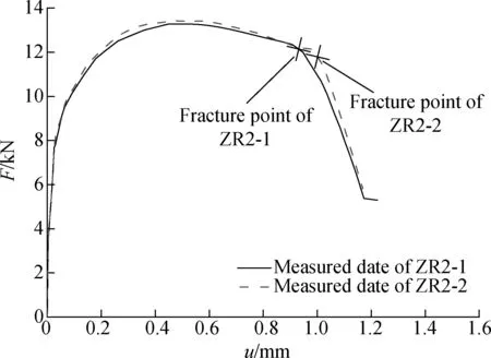
Fig.2 Load-displacement curves for notched specimens withr= 2 mm
2.2 Mesh sensitivity analysis of the finite element model
A one-quarter-scale finite element model of the notched specimen (notch radiusr= 2 mm) was established in ABAQUS, and an axial displacement load was applied (see Fig.3). To analyze the dependence of the simulation results on the computational mesh density, six different nodal mesh spacings of 2, 1.5, 1, 0.5, 0.3 and 0.1 mm are used to segment the notched part of the finite element model. The same material parameters are used for the finite element models with different mesh densities, and the specific values can be found in Tab.1 and Tab.2[18].
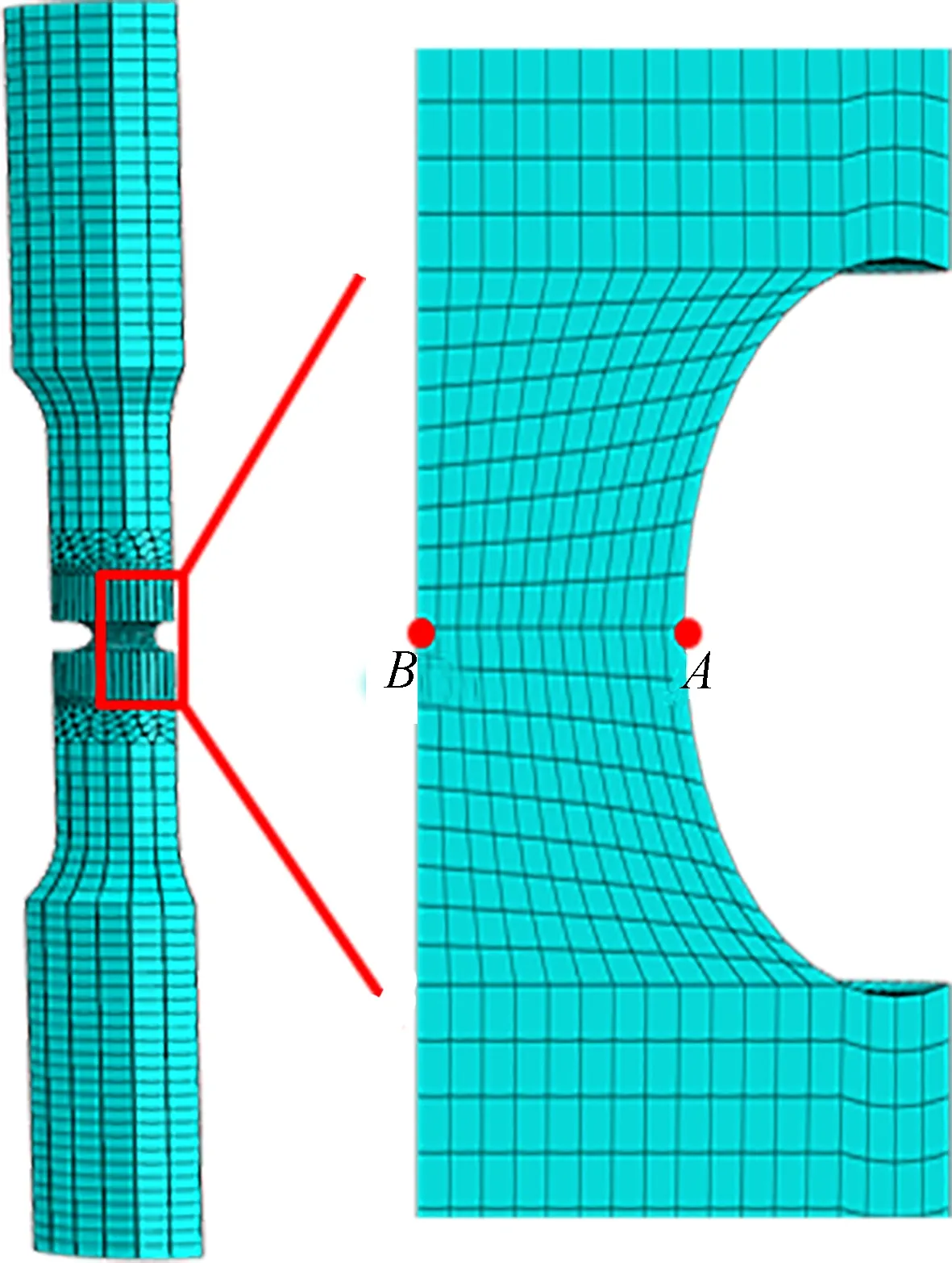
Fig.3 The finite element model for the notched specimen

q1q2q3f0fcfNfFεNSN1.90.33.610.0010.20.020.350.30.1
In Fig.4, the effective porosity volume fractionf*at PointB(located at the center of the notch, as shown in Fig.3) is extracted to show the damage evolution process. When the mesh size is larger than 1 mm, the damage evolution curves at PointBchange gradually. The 2 and 1.5 mm damage evolution curves are very similar, and the simulated damage evolution curves for the 0.3 and 0.1 mm mesh spacings appear to converge. Based on this grid convergence study, the 0.3 mm mesh spacing was used to simulate the notched specimens. The 0.1 mm mesh spacing had an overly long computation time when simulating all the specimens.

Fig.4 The damage evolution curves obtained from grid dependence studies for a notched specimen at PointB
2.3 Determination of the modified GTN damage model parameters
The nine GTN parameters of cast steel GS-20Mn5V were determined by comparing the numerical simulation load-displacement curves with the measured curves.q1,q2andq3are 1.5, 1.0, and 2.25, respectively, according to Tvergaard and Hutchinson[20]. Chu and Needleman[13]noted that the mean nucleation strainεNand the corresponding standard deviationSNwere 0.3 and 0.1, respectively, which are applicable to the majority of materials and have been widely recognized by researchers. Since the damage process and fracture mechanism of materials are highly complex, the void volume fractionsf0,fN,fc, andfFwere calibrated individually[12, 21].
2.3.1 Effect of f0on the mechanical properties
Zhang[18]summarized the GTN parameter reference for a variety of materials. The initial volume fractionf0is typically between 0.000 1 and 0.007. In this paper, three values 0.000 1, 0.002 and 0.005 are chosen to determine the influence off0on the tensile properties. As shown in Fig.5, the value off0influences the maximum load of the load-displacement curves of notched specimens. Higherf0values allow the maximum load to increase while maintaining the same slope of the curves after the final fracture point, thus leaving the fracture position largely unchanged.
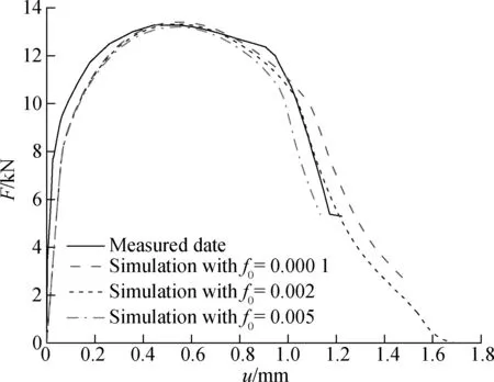
Fig.5 Effect of varyingf0on the predicted load-displacement curves compared to the measured curves
2.3.2 Effect of fNon the mechanical properties
As shown in Fig.6, thefNvalue influences the elongation of notched specimens at the fracture point. A higherfNcan lead to a lower ductility of the specimen for a constant slope of the curves after fracture.
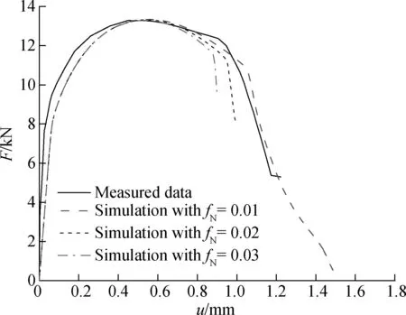
Fig.6 Effect of varyingfNon the predicted load-displacement curves compared to the measured curves
2.3.3 Effect of fcon the mechanical properties
As shown in Fig.7, increasing the coalescence void volume fraction from 0.02 to 0.04 increases the fracture position and the fracture ductility of the load-displacement curves of notched specimens, whereas the slopes of the curves after the fracture point are not affected by thefcvalues.

Fig.7 Effect offcon the predicted load-displacement curves compared to the measured curves
2.3.4 Effect of fFon the mechanical properties
The load-displacement curves with different values offFare shown in Fig.8.fFhas only a slight effect on the failure position of the notched specimens, which is related to the slope after the failure of the material. A steeper slope can be obtained with a lowerfFvalue.

Fig.8 Effect offFon the predicted load-displacement curves compared to the measured curves
2.4 Orthogonal test method
The orthogonal test method is a mathematical statistical method used to arrange and analyze a multifactor experiment with an orthogonal table[22]. The purpose of this method is to obtain the most representative combination of experimental factors with the highest efficiency.
The ranges in variation of the GTN model parameters for cast steel GS-20Mn5V, which are the factors of the array, are chosen according to Section 2.3. The porosity fractions are as follows:f0is 0.000 1 to 0.005;fcis 0.02 to 0.04;fFis 0.2 to 0.4; andfNis 0.01 to 0.03. These four parameters are divided into three levels, as shown in Tab.3, and an orthogonal test is carried out, using the orthogonal arrayL9(34), as shown in Tab.4.
Tab.3Ranges of variation in the GTN parameters for GS-20Mn5V

Levelsf0fcfFfN10.0020.020.40.0120.0050.030.30.0230.000 10.040.20.03
According to the ductile fracture mechanism,fcis greater thanf0andfNand less thanfF. Therefore, models 4, 7, and 8 should be abandoned. The load-displacement curves of the remaining 6 models were compared with the test results of the ZR2-1 notched specimen, and the results are shown in Fig.9. Based on this figure, their preferred values can be obtained by orthogonal analysis, and the optimal parameter combination in the modified GTN model for cast steel GS-20Mn5V is shown in Tab.5.
Tab.4L9(34) orthogonal array testing for the GTN model
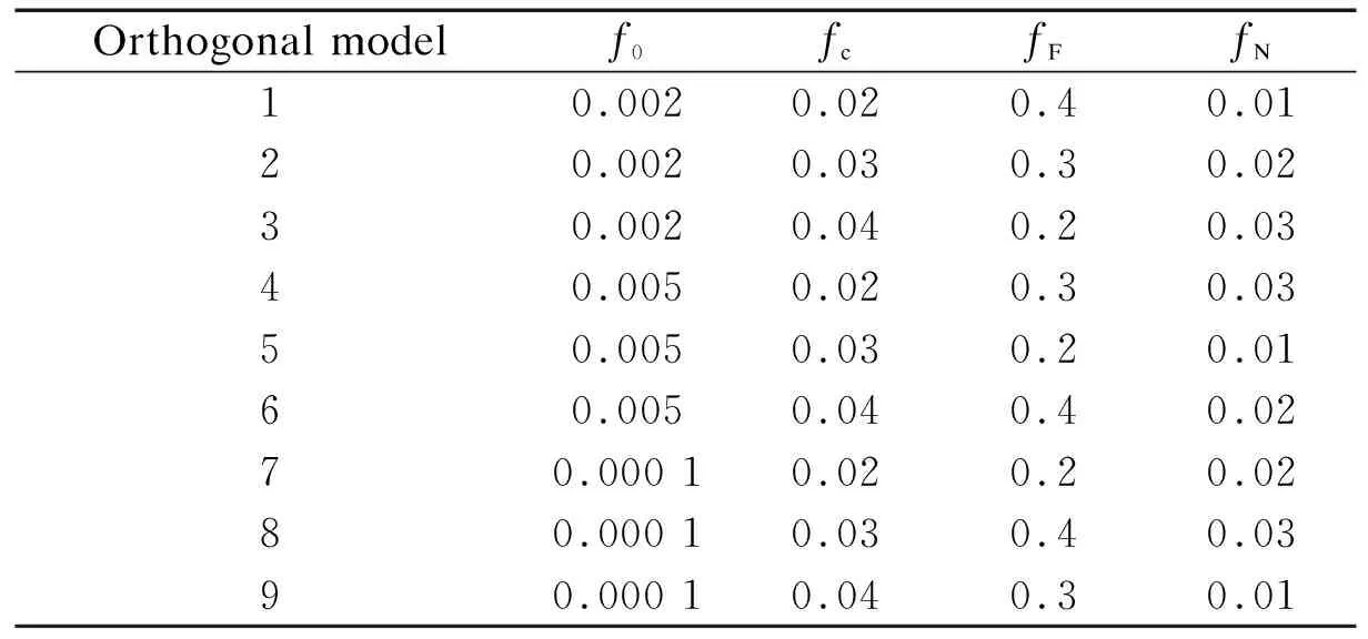
Orthogonal modelf0fcfFfN10.0020.020.40.0120.0020.030.30.0230.0020.040.20.0340.0050.020.30.0350.0050.030.20.0160.0050.040.40.0270.000 10.020.20.0280.000 10.030.40.0390.000 10.040.30.01

Fig.9 Predicted load-displacement curves of the orthogonal test models

q1q2q3f0fcfNfFεNSN1.51.02.250.0020.020.010.40.30.1
3 Damage Evolution Prediction for GS-20Mn5V
The measured and simulated (with the GTN model in Ref.[18] and with the modified GTN model) load-displacement curves of the ZR2-1 notched specimen are shown in Fig.10. The measured and predicted fracture positions for ZR2-1 are marked with a fork. By observing the locations of these three points, the predicted fracture position with the modified GTN model is closer to the actual fracture position, and, after the propagation, the slopes of the load-displacement curves also correspond well. Therefore, the modified GTN damage model with the optimal parameters accurately predicts reduction in ductility and fracture behavior. Three points along the predicted tensile curve are shown in Fig.10 to demonstrate the relationship of the failure process and damage evolution. The testing displacements are approximately 0.6, 1.0, and 1.2 mm at Points 1, 2, and 3, respectively. Point 1 is at the position of the ultimate tensile strength; Point 2 is the measured breaking point, which indicates the fracture of the specimen; and Point 3 is located at the point of complete failure of the notched specimen.
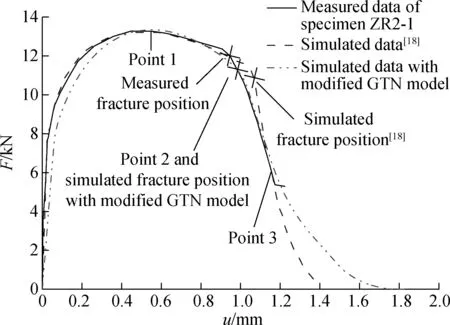
Fig.10 Simulated and measured load-displacement curves for ZR2-1 notched specimen
The damagef*evolution process of the notched specimens at PointsAandB(see Fig.3) is shown in Fig.11. The extreme damage value is set to to be 1/q1=0.666 7, i.e., the unit failure when the damage reaches the maximum value. In Fig.11, the results of the damage fraction at Point 1 are lower than the critical void volume fraction for void coalescencefc. Before Point 1, the damage evolution is slow. However, beyond this point, the load bearing capacity of the notched specimens decreases with the accelerated damage evolution. From Points 1 to 3, the damage value increases due to the nucleation and growth
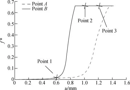
Fig.11 Damage elevation curves of ZR2-1 notched specimens at PointsAandB
of voids until failure occurs.
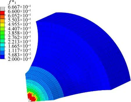
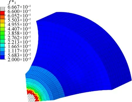
The microscopic fracture process of the specimen in Fig.12 shows the failure behavior of the notched specimens. Fig.12(a) illustrates a crack initiated at the center of the notched specimen (PointB). With increasing displacement, the crack extends to the surface of the specimen (see Fig.12(b)). Finally, the overall fracture nephogram is shown in Fig.12(c). The simulation of the crack initiation and propagation process with the modified GTN model corresponds well with the actual fracture process of notched tensile specimens[19].
4 Conclusion
A modified GTN model with mixed hardening was described to simulate the damage and fracture behaviors of notched tensile specimens. The effects off0,fN,fc, andfFon the mechanical behavior of the specimen were investigated using numerical analysis, and the optimal parameter combination in the GTN model of cast steel GS-20Mn5V was obtained by an orthogonal test method. Based on these simulated results, the damage evolution process of steel castings can be predicted simply and accurately.
杂志排行
Journal of Southeast University(English Edition)的其它文章
- Mathematical models for properties of mortars with admixtures and recycled fine aggregates from demolished concretes
- Analogy-based software effort estimation using multi-objective feature selection
- A recognition model of survival situations for survivable systems
- A weighted selection combining schemefor cooperative spectrum prediction in cognitive radio networks
- Syntheses and calculation of (E)-4-chloro-4’-ethoxystilbene and (E)-4,4’-dichlorostilbene
- Experimental study of the onset of nucleate boiling in vertical helically-coiled tubes
