Design and Implementation of Digital Fractional Order PID Controller Using Optimal Pole-Zero Approximation Method for Magnetic Levitation System
2018-09-28AmitChopadeStudentMemberIEEESwapnilKhubalkarStudentMemberIEEEJunghareAwareSeniorMemberIEEEandShantanuDas
Amit S.Chopade,Student Member,IEEE,Swapnil W.Khubalkar,Student Member,IEEE,A.S.Junghare,M.V.Aware,Senior Member,IEEE,and Shantanu Das
Abstract—The aim of this paper is to employ fractional order proportional integral derivative(FO-PID)controller and integer order PID controller to controlthe position of the levitated object in a magnetic levitation system(MLS),which is inherently nonlinear and unstable system.The proposal is to deploy discrete optimalpole-zero approximation method for realization of digital fractional order controller.An approach of phase shaping by slope cancellation of asymptotic phase plots for zeros and poles within given bandwidth is explored.The controller parameters are tuned using dynamic particle swarm optimization(dPSO)technique.Effectiveness ofthe proposed controlscheme is verified by simulation and experimental results.The performance of realized digital FO-PID controller has been compared with that of the integer order PID controllers.It is observed that effort required in fractional order control is smaller as compared with its integer counterpart for obtaining the same system performance.
I.INTRODUCTION
IN 1914,American inventor Emile Bachelet presented his idea of a magnetically levitated(maglev)vehicle with a display model.In magnetic levitation system(MLS),ferromagnetic object levitate by the electromagnetic force induced due to electric current flowing through coil around a solenoid[1]-[5].The MLS is inherently nonlinear and unstable[6]-[10].However,the advantage is that,as the suspended object has no mechanical support,there is no friction and noise.This allows us to position it accurately—a major advantage,explored in many applications such as magnetically levitated train,magnetic bearing,conveyor system,etc.[1].
In recent years,various methods have been proposed to improve control in MLS-based applications.In 2006,Chiang et al.proposed the concept of integral variable-structure grey control[2].Yang et al.introduced the concept of adaptive robust output-feedback control with K-filter approach in 2008[3].In 2011,Lin et al.developed an adaptive PID controller and a fuzzy compensation controller for MLS[1].In the same year,Morales et al.proposed generalized proportional integral output feedback controller[4].Recently in 2014,Lin et al.proposed a function-link cerebellar model articulation control system design based on the neural network concept[5].However,in spite of allthese developments,there is scope for improving efficiency of the controller.The energy required to achieve and maintain the object’s position(in the face of disturbances)form an importantpartof improving the control action.The aim of this paper is to control and maintain the desired object’s position,with lesser controller effort.The controller effort minimization is reported in literature[11]-[14].
The conventional integer order controllers such as,PD and PID controller have been applied in industry for over half-acentury to controllinear and nonlinear systems[15].Recently,such control schemes have been extended to their generalized form using fractional calculus[16],[17](differentiation and integration of an arbitrary order).The FO-PID controller has fractional differ-integrator operations.This makes the controller have memory(i.e.,its action will memorize its past states)and avoids instantaneous actions.Using the definition of convolution integral,the expression for the fractional integration(which also is embedded in the fractional differentiation)can be written as the convolution of the function and the power function,which is elaborately explained in[17].
In last few decades,the fractional order approach to represent the plant and its controllers are increasingly used to describe the dynamic process accurately[17].The fractional order transfer function is approximated by integer order transfer function using various methods[16]-[20].The proposed method can achieve the desired accuracy over a much larger bandwidth than has been achieved using earlier methods.In applications,where non-integer order controllers are used for integer order plant,there is more flexibility in adjusting the gain and phase characteristics as compared to integer order controllers.This flexibility makes fractional order control a more versatile tool in designing robust and precise control systems.
This paper presents the control of magnetic levitation system using FO-PID controller based on optimal pole-zero approximation method.An algorithm is developed to realize digitalFO-differentiators and FO-integrators.The proposed design procedure aims to ensure that the performance is within required tolerance bandwidth.Five parameters(kp,ki,kd,α,β)of FO-PID need to be tuned for designing the controller.This paper utilizes dynamic PSO optimization(dPSO)method to achieve the required values.Finally,a comparative study of the performance parameters of the controller is presented to evaluate the advantages of deployment of FO-PID against the conventionally used integer-order controllers.The control effort minimization by FO-PID controller is quantified and demonstrated.
This work is organized as follows:Section II presents the system description.Design procedure of proposed digital FOPID controller using discrete optimal pole-zero approximation method and dPSO technique is discussed in Section III.In Section IV simulation and experimental results on MLS are provided to validate effectiveness of the proposed controller.Paper concludes with a summary of the results obtained in Section V.
II.SYSTEM IDENTIFICATION OF MLS MODEL
A laboratory scale magnetic levitation system is used to evaluate the performance of proposed controller in a controlled environment.MLS levitates an object(metallic ball with mass m)in a desired position by controlling the electromagnetic field counteracting the gravitationalforce.The applied control inputis voltage,which is converted into currentvia embedded driver[21].Fig.1 shows the schematic diagram of MLS.The system model is nonlinear,that means at least one of the two states(i–current,x–ball position)is an argument of a nonlinear function.The nonlinear modelof MLS relating the ball position x and coil current i is given as(1):

where k is a constant depending on coil(electromagnet)parameters,m is the mass of sphere,g is gravitational force,k1is an inputconductance,u is controlvoltage,and x is a ball position.The values ofthese parameters are given in Table A.1 of Appendix A.A relation between control voltage x and coil current i is given in(2).The control signal ranges between[-5V,+5V].
A.Linearization of MLS Model
The nonlinear form of maglev model is linearized for analysis of the system[21].The linear form of the model is obtained from(1)as follows:

Fig.1 Schematic diagram of MLS.

where f(x,i)=ki2/(mx2).
Equilibrium point is calculated by setting=0,

Linearization is carried out about the equilibrium point of xo=-1.5 V(the position is expressed in volts),io=0.8 A[8].Using series expansion method,(5)is obtained.

Application of Laplace transform on(5)simplifies it to(6).

where Ki=2mg/ioand Kx=-2mg/xo.
Linearized modeltransferfunctio pn(6)has two poles,one of which is in the righthalf plane atwhich makes the MLS open-loop unstable.Transfer function,obtained by the linearization,is verified using system identification procedure.
B.Integer Order System Identification of MLS Model
System identification is a process for obtaining mathematical model using input and output system response.The identified model response should fi t with measured response for inputapplied to the system model[21].Usually there are two methods for system identification,least mean square(LMS)method and instrumental variable method.The identification of MLS is generally accomplished via traditionalleastsquares method,and is implemented in MATLAB[21],[22].
As MLS is unstable,it has to be identified with a running,stabilizing controller i.e.closed loop identification.Fig.2 shows the scheme of unstable system identification.LMS method minimizes error between the model and plant output.The optimal model parameters,for which the square of the error is minimal is the result of identification.In order to carry out identification experiment,a discrete controller has to be applied,in the absence of which,the ball falls down,rendering identification impossible.The reference signal r(t)i.e.,random binary sequence signal is given to excite the MLS and output y(t)is monitored.2500 samples ofthe input,output signals are collected from the system with sampling period of 0.01 s.

Fig.2.Block diagram of MLS control and close loop system identification.
Fig.3 presents the comparison between measured and identified model output.Input and output data is taken from MLS system for real-time identification.The best fit obtained is 90.78%forintegerorderidentification,which gives close loop discrete transfer function as

where Y(z-1)is complete system transfer function,C(z-1)is controller transfer function,and G(z-1)is MLS model transfer function in discrete domain.
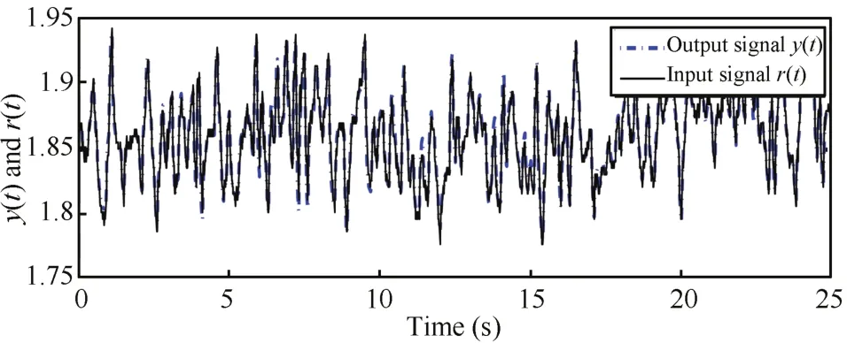
Fig.3.Measured and simulated model output.
III.DESIGN OF DIGITAL FRACTIONAL ORDER PID CONTROLLER
A.Fractional Calculus
Fractional calculus is a branch of mathematics that studies the possibility of taking real or complex number powers of differentialand integraloperator.Basic definitions of fractional calculus and approximation of fractional integrator and fractional differentiator are described in[16],[17].The real order operator is generalized as follows:

whereα∈R.
Some popular definitions used for general fractional derivatives/integrals in fractional calculus are:
1)Riemann-Liouville(RL)definition is given in(9).

for(n-1)≤α<n,where n is an integer,αis a realnumber,andΓis Euler gamma function.Laplace transform of the RL fractionalderivative/integral(9),under zero initialconditions,is given in(10)

2)Another definition is based on the concept of fractional differentiation i.e.,Grunewald-Letnikov(GL)definition.It is given in(11)

3)One more option for computing fractional derivatives is Caputo fractional derivative,its definition is as follows:

where(n-1)≤α<n,n is an integer,andαis a real number.
Initial conditions for Caputo’s derivatives are expressed in terms of initial values of integer order derivatives.It is noted that for zero initialconditions RL,GL,and Caputo fractional derivatives coincide.Hence,any of the mentioned methods may be used,using the case of zero initial conditions.That would then eliminate the differences arising due to different initial conditions(amongst the three methods).
B.Digital Realization of Fractional Order Differintegrals With Optimal Pole-Zero for Phase Shaping
The aim behind the choice of frequency domain rational approximation of FO-PID controller is to realize the controller in real time using existing analog/digital filters[16]-[20],[23]-[25].Precise hardware implementation of multidimensional natured of fractional order operator is difficult.However,recent research work revealed that band-limited implementation of FO-PID controllers using higher order integer transfer function approximation of the differintegrals give satisfactory performance[26].This paper,hence utilizes optimalpole-zero algorithm to realize fractionaldifferintegrals in the frequency domain.
1)Optimal Pole-Zero Approximation for Phase Shaping:Any rational transfer function is characterized by its poles and zeros.The Bode magnitude plot of non-integer order transfer function has a slope of±α20 dB/dec and the Bode phase plot lies in the range of ±α90°(α is a real number).This is achieved by the interlacing of realpoles and zeros alternately on the negative realaxis[19],[20],[27],[28].Thus,depending on the error bandϵaround required phase angleαreq=α90°and the frequency band of interest(ωL,ωH),the n th order approximation is obtained[28].The proposed algorithm is developed to obtain the number of optimal pole-zero pairs to maintain the phase value within the tolerance,of around 1°.In this algorithm,poles and zeros given by(13)are obtained as follows:
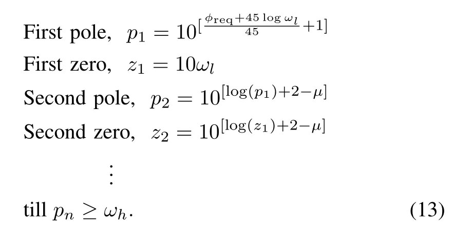
As a particular case,asymptotic phase plot for fractional order integrator circuit having α =-0.4,φreq=-36°,ωL=0.1 rad/s andωH=100 rad/s is given in Figs.4-6.The selection of three pairs of poles and zeros withα=-0.4 fraction is shown in Fig.4.The asymptotic phase plot is a straight line atφreq,but the actual phase plot is oscillating about asymptotic phase plot,apart from thatthe average value of phase angle-37.31°is also different from φreq.In Fig.4 the required correction ofphase is achieved overthree decades by three pole-zero pairs only,which is however less in pursuit of more accuracy.This problem is rectified by increasing the pole-zero density,i.e.,having more pole-zero pairs in the desired frequency band.Number of pole-zero pairs depend on the permissible error and the desired band of frequency.

Fig.4.Asymptotic phase plot with three pole-zero pairs forα =-0.4(-36°).
Generally,three pole-zero pairs per decade give the phase plot withinε= ±1°error,but it depends on the value ofα as well.For the same parameters,i.e.,α =-0.4,φreq=36°,ωL=0.1 rad/s and ωH=100 rad/s with seven pole-zero pairs,phase plot is shown in Fig.5.The actual phase plot is oscillating with rms error of 0.6471°(< 1°).Apart from that,average value of phase angle(-35.9999°≈ -36°)is same asφreq.Moreover,this is achieved over 3 decades of cycle by seven pole-zero pairs.In order to maintain the phase margin tolerance within the lower limits,more polezero pairs in the desired frequency band are required.This can be done by adjusting z1,p2,z3,...,closer towards left.To achieve this shift,design parameterµis introduced.Frequency band of constant phase shrinks on both the ends with increasingµfor constant number of pole-zero pairs.Fig.6 shows the basic idea of frequency band tightening.The problem regarding frequency band shrinking is tackled by designing the rational approximation on wider frequency band(ωl/10γ,10δωh)followed by curtailing the frequency overhang on either side,such that the phase remains within φreq± εin range of(ωl,ωh).Nominal values to expand frequency band areγ=3,δ=2.
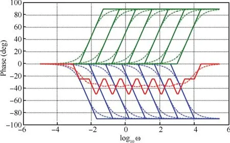
Fig.5. Asymptotic phase plot with seven pole-zero pairs.

Fig.6. The basic idea of frequency band tightening.
2)Design of Digital Fractional Order Integrator:The key point in digital implementation of fractional order controller is discretization of fractional order differintegral[24],[27]-[29].Contributions related to the discretization have been reported in literature[30]-[33].The pole-zero pairs obtained by algorithm in the above case are discretized using first order hold(foh),zero order hold(zoh),Tustin operator,impulse invariant,matched pole-zero,and Tustin with prewarp frequency methods.In Fig.7,Bode plot for s-0.4digital integrator is shown and it depicts that digital integrator with Tustin approximation method matches closely with continuous time integrator.Tustin approximation method with a sample time of 0.01 s is used for discretization.To relate s-domain and z-domain transfer functions,Tustin and bilinear methods use the following approximation as(14).

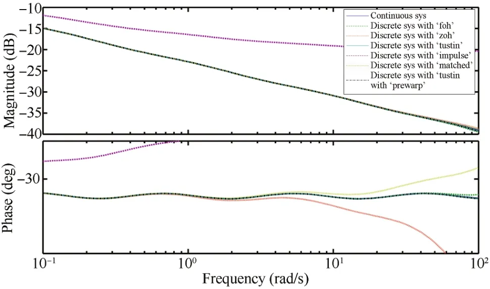
Fig.7. Bode plot of s-0.4 digital integrator.

Fig.8. Digital FO-PID controller.
The optimal pole-zero algorithm for digital fractional integrator of s-0.4within desired band of frequencyωL=0.1 rad/s andωH=100 rad/s gives pole-zero pairs which are listed in Table I with gain value 0.010127.
Digital fractional differentiator is designed along the lines of approach similar to thatof digitalfractionalintegrator.The architecture ofdigitalFO-PID with digitalfractionalintegrator and digital fractional differentiator is shown in Fig.8.

TABLE I THE POLE-ZERO PAIRS OF THE RATIONAL APPROXIMATION OF s-0.4 ON(10-1,102)rad/s
3)Dynamic Particle Swarm Optimization:Recently,many researchers have focused on fractionalordercontrollers tuning,and have obtained meaningfulresults[34]-[47].In this work,dPSO method is used to tune the gains and orders of the controller.PSO is a method for optimizing hard numerical functions,analogous to social behavior of flocks of birds,schools of fish,etc.Here,each particle in swarm represents a solution to the problem defined by its instantaneous position and velocity[48].The position vector of each particle is represented by unknown parameters to be ascertained.In present case,five control parameters(kp,ki,kd,α,β)of FOPID controller need to be ascertained.The desired number of particles is known as population.The population is varied to carry out a search in multidimensional space.Each particle in population will travel with the updated velocity and direction to converge as early as possible to the optimalsolution point.Dynamic PSO is an improvement in PSO by adding the product of differences in objective function value between a particle and its individual best or the global best.Here,the change in position of a particle is directly proportional to iteration,which furtherdepends on individualbest,globalbest,and a random velocity[49].dPSO searches the workspace similar to a simple PSO and velocity of a particle is obtained by

where,vid:velocity of a particle,pid:individual best,xid:current position of a particle,pgd:global best,rand:random function,sf1,sf2,sf3:to scale the calculated value in the range ofthe controlvariable,signis:function which generates random positive or negative value.
Population size is taken as 100,maximum iteration is set as 50,lower and higher translation frequencies are taken as ωL=0.1 rad/s and ωH=100 rad/s.Integral time absolute error(ITAE)is chosen as performance criterion.The values of controller parameters,obtained from dPSO,are implemented in PD,PID,and FO-PID controller in simulation as well as in real time mode on MLS.The optimized values of the controllers are presented in Table II.
IV.MLS CONTROL:SIMULATION AND HARDWARE
A.Closed-Loop Control System Simulation
Controlof MLS using optimized PD,PID,and FO-PID controlleris studied by MATLAB simulation.A sinusoidalexcitation signalis used to study the effects.The controller generates a compensating controlsignal(based on the positionalerror)to achieve desired ballposition.Controller parameters are tuned using dPSO method as discussed in Section III-B-3.Figs.9-11 present simulation results of the controlled output of MLS using PD,PID,and FO-PID controllerrespectively.Here,encircled part pointed by an arrow shows deviation between desired and actual ball position.

TABLE IIDPSO OPTIMIZED GAIN AND FRACTIONAL ORDER VALUES USED FOR DIFFERENT CONTROLLERS(α:ORDER OF INTEGRATOR,β:ORDER OF DIFFERENTIATOR)

Fig.9.Controlled output result of MLS using PD.
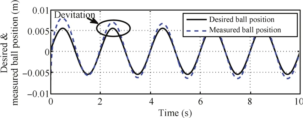
Fig.10.Controlled output result of MLS using PID.

Fig.11.Controlled output result of MLS using FO-PID.
The measured and desired ball positions with PD,PID,and FO-PID controllers are quantitatively presented in Table III.The simulation results indicate that deviation between measured and desired ballpositions by using dPSO tuned FOPID controller,is less as compared to PD or PID controllers.
Error values presented in Table III are calculated using(16)


From the data presented in Table III,itis observed that FOPID controllertracks the desired position more efficiently than PD or PID controllers.
B.Real Time Implementation of Closed-Loop System
The MLS used for experimentation is shown in Fig.12.Due to high nonlinearity and open-loop instability,MLS system is a very challenging plant.Assembly of MLS consists of a mechanical unit labeled A in Fig.12.Analogue control interface unitlabeled A is used to transfer controlsignals between computing system and MLS.Advanced PCI1711 I/O card has been inserted into a PCI computer slot and connected with SCSIadapterbox using SCSIcable.Mathworks software tools are used to implementcontrolalgorithm.Itincludes MATLAB control toolbox,real time windows workshop(RTW),real time windows target(RTWT),and visual C as programming environment.The flowchart required to obtain executable file is shown in Fig.13.RTW builds a C++source code from the simulink model.C code compiler compiles and links the code to produce executable program.RTWT communicates with executable program acting as the control program and interfaces with hardware through input/output board.The block diagram of MLS close loop control is shown in Fig.14.
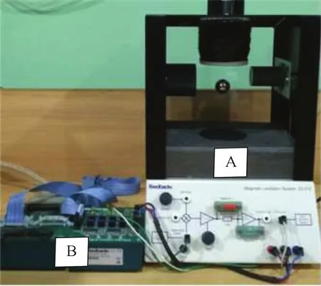
Fig.12.Experimental setup.
1)Experimental Results Using a PD Controller:The measured and desired ballpositions using realtime PD controller is shown in Fig.15(a)and controlsignal c(t)before digitalto analog(D/A)conversion is given in Fig.15(b).This control signal is used to levitate the object at desired position.The plantinputsignal m(t)after D/A conversion and outputsignal y(t),captured on the digital storage oscilloscope(DSO),is presented in Fig.16.
The controleffortrequired by controllerto maintain object’s position can be observed from the control signal c(t).The ball position is tracked by infrared sensor and is fed back to Simulink environment via analog to digital(A/D)converter.It is observed from Figs.15 and 16 that there is more deviationin ball position and control effort required by the controller,and is higher in case of PD controller.Hence,integralaction is added to the PD controllerto achieve an improved controlover desired ball position.The quantitative analysis of desired and actual ball position achieved by the controller is presented in Table IV and the control effort analysis of controller is shown in Table V.

TABLE III MEASURED AND DESIRED BALL POSITIONS FOR DIFFERENT CONTROLLERS IN SIMULATION

Fig.13.Control system development flow diagram.

Fig.14.Block diagram of MLS close loop control.
2)Experimental Results Using a PID Controller:Fig.17(a)shows measured and desired ball positions using PID controller and output of controller c(t)is shown in Fig.17(b).The captured controller output signal c(t)and output signal are presented in Fig.18.The deviation in the ball position is minimized to an extent by employing the PID controller.However,the control effort required by controller is still similar to that of PD controller while achieving the improvement.
3)Experimental Results Using a FO-PID Controller:The deviation in ballpositions using realtime FO-PID controller is shown in Fig.19(a).It depicts that error in desired and actual ball positions has reduced in comparison to both PD or PID control actions.The control signal c(t)of FO-PID controller is presented in Fig.19(b).It shows that effort required by the controller is least as compared to PD or PID controllers.Plant input signal m(t)and output signal y(t)are presented in Fig.20.

TABLE IV MEASURED AND DESIRED BALL POSITIONS FOR DIFFERENT CONTROLLERS IN REAL TIME IMPLEMENTATION
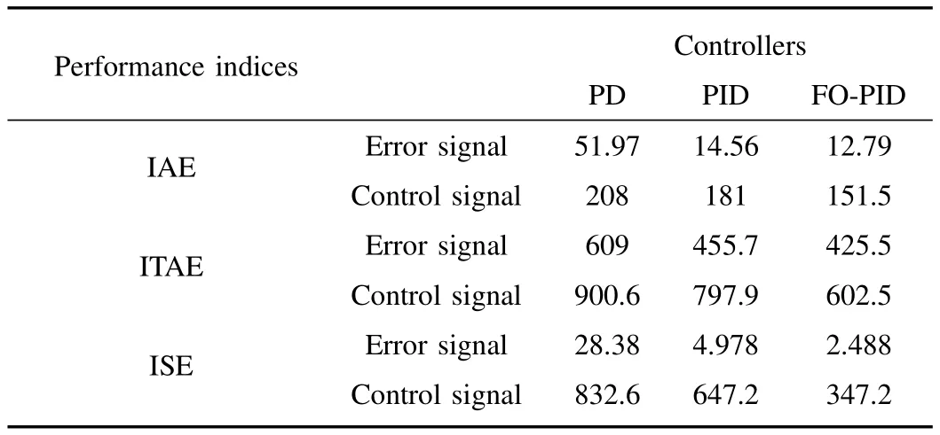
TABLE V CONTROL EFFORT ANALYSIS OF DIFFERENT CONTROLLERS IN REAL TIME IMPLEMENTATION

Fig.15.(a)Controlled output result of MLS using a PD controller.(b)Control signal of PD controller.
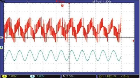
Fig.16.Experimental PD controller output and object’s trajectory captured on DSO.

Fig.17.(a)Controlled output result of MLS using a PID controller.(b)Control signal of PID controller.

Fig.18.Experimental PID controller output and object’s trajectory captured on DSO.
From the data presented in Table IV itis observed that FOPID controller has improved the position accuracy of MLS compared to PD or PID controllers in real time implementation.Also,the percentage error is least for FO-PID controller.
The control effort required by PD,PID,and FO-PID controllers is calculated using integral absolute error(IAE),ITAE,and integral square error(ISE).The analysis has been carried out for a period of 100s and is tabulated in Table V.Fig.21 represents the control effort analysis in pictorial form.The error signal is maximum in the case of PD controller and least in the case of FO-PID controller.The control signal also follows the same pattern and is least in case of FO-PID controller,leading to inference thatthe controleffortin terms of power required by the FO-PID controller to maintain the ball position is least amongst the three controllers.

Fig.19.(a)Controlled output result of MLS using a FO-PID controller.(b)Control signal of FO-PID controller.
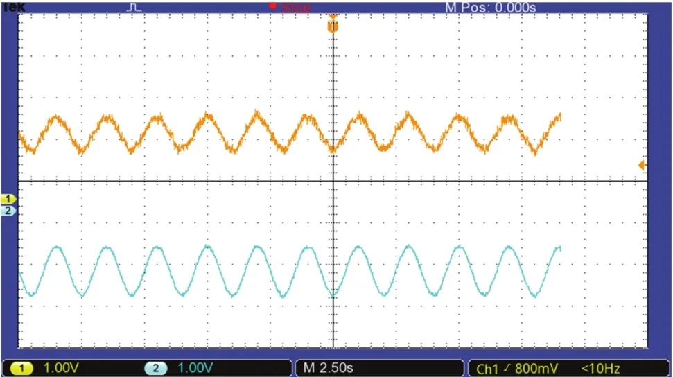
Fig.20.Experimental FO-PID controller output and object’s trajectory captured on DSO.

Fig.21.Control effort analysis.
From the analysis,it infers that PID controller is better than PD controller through performance characteristic.FOPID controller shows slight improvement over PID controller,but the effort required is appreciably less for the same improvement.Thus proving superiority of FO-PID over integer order controllers.
4)Disturbance Injection Analysis of Controllers:The effect of disturbance is studied by injecting step input to MLS and effect of increased load is studied by introducing another metallic ballin levitation system as shown in Fig.22.The step is applied after interval of 25 s on initiation of the input while another ball is introduced manually after 35 s.The measured and desired ball positions using a PD controller are presented in Fig.23(a)and the control signal of a controller is shown in Fig.23(b).PD controller output and object’s trajectory as captured on DSO is presented in Fig.24.
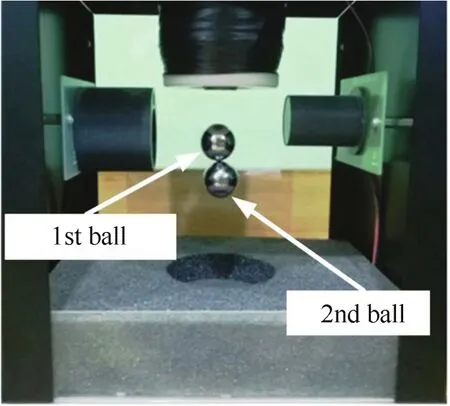
Fig.22.Levitation of two metallic balls.
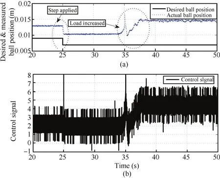
Fig.23.(a)Controlled output result of MLS using a PD controller.(b)Control signal of PD controller.
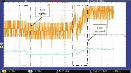
Fig.24.Experimental PD controller output and object’s trajectory captured on DSO.
The instant of step applied in input signal and the instant of the addition of extra load are demonstrated by circles marked on figures.Overshoot is observed at the instant of step and after introducing second ball in levitation system.The deviation in ball position is higher as load is increased and greater amountofeffort(powerconsumption,as indicated by high switching fluctuations in the voltage graph)is required by controller to achieve desired ball position.
Similar analysis for PID and FO-PID controllers is presented in Figs.25-28.These figures lead to inference that in case of PID controller,the deviation in ballposition is high and greater amount of effort is required by controller to achieve ball position as compared to FO-PID controller.Comparison shows that FO-PID controller requires lesser effort to levitate the object and effect of disturbance is less as compared to PD or PID controllers.
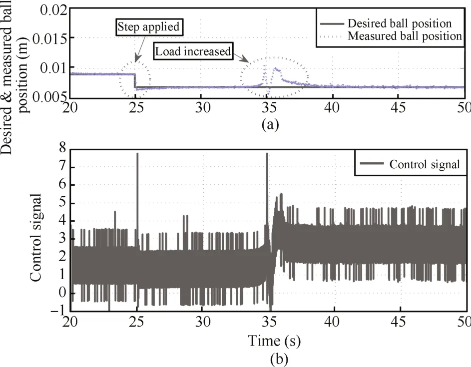
Fig.25.(a)Controlled output result of MLS using a PID controller.(b)Control signal of PID controller.

Fig.26.Experimental PID controller outputand object’s trajectory captured on DSO.
V.CONCLUSION
In this paper,digital FO-PID controller is applied on MLS to improve the positional accuracy and control effort.A new discrete optimal pole-zero approximation method is proposed for realization of controller.This method provides the optimal number of pole-zero pairs to maintain the phase value within the tolerance,of around 1°.dPSO method is used for tuning the parameters of controller.The performance analysis for integer and fractional order controllers have been carried out in both simulation and experimentation.The results show that a better controlover position accuracy with lesser efforts(over conventionalmethods)can be achieved.In practicalterms,this efficiency improvementtranslates to betterfuelefficiency.This paper provides a basis for evaluating the utility of fractional order controlto improve the performance ofpower conversion systems and precision robotic applications.

Fig.27.(a)Controlled output result of MLS using a FO-PID controller.(b)Control signal of FO-PID controller.

Fig.28.Experimental FO-PID controller output and object’s trajectory captured on DSO.
APPENDIX A
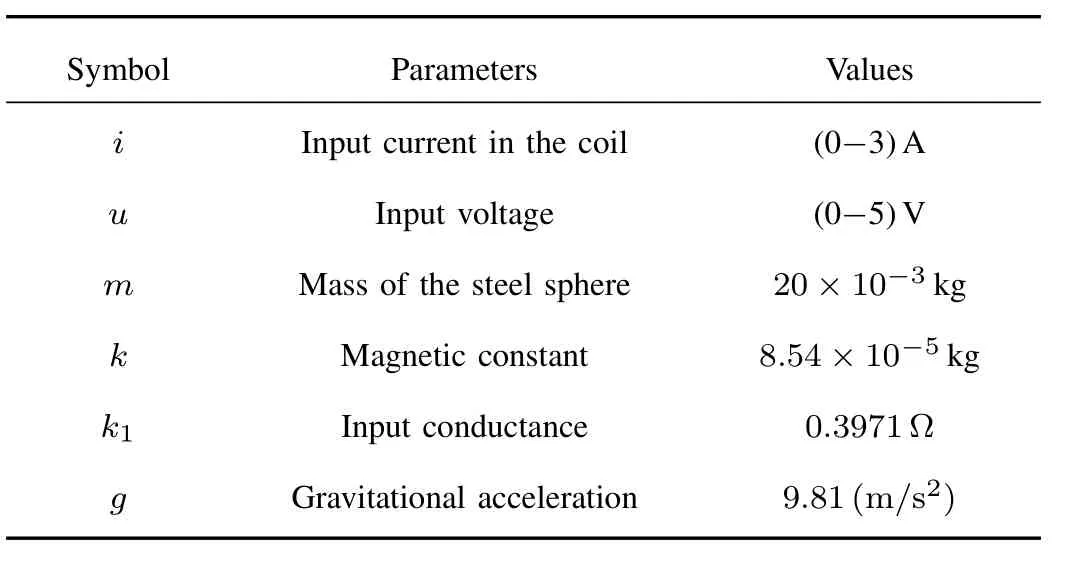
TABLE A.1 Parameters of MLS
杂志排行
IEEE/CAA Journal of Automatica Sinica的其它文章
- Iterative Learning Control With Incomplete Information:A Survey
- Fundamental Issues in Networked Control Systems
- Adaptive Neural Network-Based Control for a Class of Nonlinear Pure-Feedback Systems With Time-Varying Full State Constraints
- A Dynamic Road Incident Information Delivery Strategy to Reduce Urban Traffic Congestion
- Feed-Forward Active Noise Control System Using Microphone Array
- Energy Efficient Predictive Control for Vapor Compression Refrigeration Cycle Systems
