Energy Efficient Predictive Control for Vapor Compression Refrigeration Cycle Systems
2018-09-28XiaohongYinandShaoyuanLi
Xiaohong Yin and Shaoyuan Li
Abstract—Vapor compression refrigeration cycle(VCC)system is a high dimensional coupling thermodynamic system for which the controller design is a great challenge.In this paper,a model predictive control based energy efficient control strategy which aims at maximizing the system efficiency is proposed.Firstly,according to the mass and energy conservation law,an analysis on the nonlinear relationship between superheat and cooling load is carried out,which can produce the maximal effect on the system performance.Then a model predictive control(MPC)based controller is developed for tracking the calculated setting curve ofsuperheat degree and pressure difference based on model identified from data which can be obtained from an experimental rig.The proposed control strategy maximizes the coefficient of performance(COP)which depends on operating conditions,in the meantime,it meets the changing demands of cooling capacity.The effectiveness of the control performance is validated on the experimental rig.
I.INTRODUCTION
T HE energy consumption by large scale industrial process plants seriously influences and restricts the development of economics and environment.For example,subjected to the influence of the tropical hot and humid climate and overpopulation within a narrow territory,Singapore consumes a large amountof electricity and suffers from high environmentalcost.In particular,one of the major factors is the electricity usage for running air-conditioning which accounts for more than 52%of the total electrical energy generated[1].The vapor compression refrigeration cycle(VCC)is a core element in the heating,ventilation,and air-conditioning(HVAC)system which is composed of compressor,condenser,expansion valve,and evaporator.For the purpose of minimizing energy consumption while maintaining the demand of human comfort,the VCC system needs to be controlled more effectively.
The development of effective control scheme of VCC system has become a hot issue attracting the attention of researchers.Traditionally,for controller design,the PI or PID feedback control algorithm is widely used in air-conditioning fields due to its simplicity[2]-[5].Usually,the process is identified to be a first order plus time-delay system in which the temperature of room is taken as the controlled variable and the damper opening degree as the manipulated variable[3],and step tests were conducted to determine the process parameters.Ziegler-Nichols vibration method orother methods were used to compute the PID controlparameters for practicalcontrolsystems[4],and then the superheatof evaporator was controlled by the regulation of expansion valve opening.Recently,artificial intelligence is introduced in air-conditioning systems[6]-[8].In[7],artificial neural network(ANN)was used as a modeling tool for temperature and relative humidity of the automotive air conditioning system.Reference[9]proposed a gain-scheduled-control-based strategy with compressor speed and the opening of expansion valve to control superheat and pressure difference between condenser and evaporator at a fixed point.Since the model predictive control(MPC)is good at dealing with the constraints,it is widely used in different fields[10],[11].The application of MPC can also be found in the research of the VCC systems,e.g.,[12]developed an MPC,which used expansion valves and water flow valves to controlthe superheatof evaporator and cooling load,and the evaporator pressure regulation was performed by the compressor speed through a PI controller.Reference[13]presented a linear matrix inequality-based robust model predictive control strategy for temperature control of an airconditioning system.
Previous researches were mostly dedicated to stabilize the operating conditions(state parameters)of the VCC system,while taking the system efficiency into consideration has become a new focus of research[14],[15].Reference[16]identified a single-inputsingle-output(SISO)modelto control the evaporator superheat with expansion valve,and obtained energy saving of about 2%by experiment.Although some of these researches have been validated for the effectiveness of the energy saving,considering the nonlinear relationship between the changes ofcooling load and superheat,meanwhile they also deal with the strong coupling between the control variables,and thatis where further researches are stillneeded to be done.
In this paper,a novelenergy efficientcontrolstrategy based on the MPC method is proposed to regulate system efficiency while meeting changing demands forcooling load.To improve the measure of system efficiency called COP,a model to describe the measured relationship between superheat and cooling load is presented firstly to obtain in real-time the minimum setting value of superheat which can produce the maximal effect on the system performance.Then an MPC is employed to track the pressure difference and superheatwhen the cooling loads change.Experiments are carried outto verify the effectiveness of the proposed control strategy.
The remainder of the paper is organized as follows.Section IIdetails the VCC system.Section IIIproposes a controlstrategy which is used to optimize the coefficient of performance(COP).Experimentalresults are presented in Section IV which justify the effectiveness of the proposed controllers.Section V summarizes the main conclusions.
II.SYSTEM DESCRIPTION OF THE VAPOR COMPRESSION REFRIGERATION CYCLE
A typical single vapor compression cycle system shown in Fig.1 has four components:a compressor,a condenser,an expansion valve,and an evaporator.The circulating refrigerant as saturated vapors enters the compressor and is compressed into superheated vapors which have a higher pressure and higher temperature.The compressed,superheated refrigerant vapor is then routed through the condenser,in which the refrigerant is cooled and condensed into a liquid phase by flowing through a coilor tubes with cool fluid flowing across the coil or tubes.This process called condensation finishes the energy transformation from refrigerant to outside.After being condensed,the refrigerant as a sub-cooled liquid at a high pressure enters the expansion valve where the pressure is reduced abruptly.At the exit of the expansion valve the refrigerant is generally in two-phase flow state with a low pressure.The cold fluid then enters the evaporator,where the fluid evaporates and the heatofambientairis transferred to the fluid.Afterthe evaporation process,the refrigerantas saturated vapors is routed back into the compressor to complete the refrigeration cycle.
The parameters describing the system characteristics include the superheat of evaporator(Tesh),the pressures of evaporator and condenser(Pe,Pc),the superheat and supercooling degrees of condenser(Tcsh,Tcsc),and the temperatures of refrigerantand air atoutlets of evaporator and condenser(Tero,Teao,Tcro,Tcao).In addition,the compressor speed(Fcom),the air flow rates of evaporator and condenser(˙mea,˙mca),and the expansion valve opening(vo)are adjustable.
The pressure-enthalpy relation of VCC system which is useful to describe the system from the pointof view of energy consumption is shown in Fig.2.The process from point 1 to point 2 in Fig.2 is the compression which is an isentropic process,the process from point2 to point3 is the condensation with a constant condensation pressure,the expansion from point 3 to point 4 is an isenthalpic process,and the process from point 4 to point 1 is the evaporation with a constant evaporation pressure.Enthalpy is a thermodynamic potential,which is the preferred expression of system energy changes.The difference between the enthalpy of point 1 and point 4 represents the energy absorbed by the refrigerant across the evaporator.

Fig.2. Pressure and enthalpy diagram.
III.ENERGY EFFICIENT CONTROL OF VCC SYSTEM A.Control Strategy
As mentioned,this paper focuses on maximizing system efficiency with varying cooling demands.It is significant to ensure that superheated refrigerant exits the evaporator preventing physicaldamage in the VCC.However,minimized superheat of evaporator can improve the heat exchanging efficiency of two-phase region so that COP could be increased.Therefore,the superheat(Tesh)should be regulated to a reasonably lower setting value,while ensuring safe and stable operation.When the pressure of condenser(Pc)is reduced,the pressure of evaporator(Pe)is increased,which means the pressure difference between condenser and evaporator(Pd)is decreased,the energy saving of compressor could be achieved effectively.Therefore,the pressure difference between condenser and evaporator(Pd)is also an important variable to be controlled,which is better shown to be disturbance rejection and noise attenuation as a feedback variable than evaporator pressure alone[9].The superheat and pressure difference during the whole refrigerant cycle are affected by the compressorspeed and the opening ofexpansion valve.The process variables chosen in this research are defined in Table I.

Fig.3.The proposed energy efficientcontrol structure.
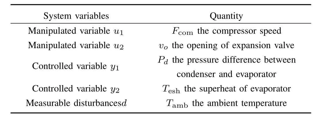
TABLE I THE VARIABLES OF PROPOSED CONTROLLER
Fig.3 presents the block diagram of the proposed control structure used in this research.The inner loop is composed of a stand-alone MPC and the VCC system,the outputs of which as feedback signals enter the inner loop controller.The outer loop consists of a PI controller and a model of nonlinearrelationship between the cooling load and superheat.According to the demands of cooling load,the setting value of superheat is determined,and the differences between the setting values and actualvalues enterthe MPC as the controller inputs,via which the outerloop is connected to the inner loop.After solving the proposed optimization problem in the MPC formulation,the optimized compressor speed and the opening of expansion valve as controller outputs enter the VCC system.Thus a closed-loop cascade control circuit has been realized.
B.Outer Loop Design
In orderto meetthe differentcooling and comfortdemands,the VCC system is operated over a wide temperature and pressure range while the superheat is kept at low values,which is an important and necessary factor to achieve energy efficiency and safe operation.Minimalstable superheat(MSS)is defined as a critical minimal degree of stable refrigerant superheatwhich can be used forthe proposed controllerdesign[17].The refrigerant exiting the evaporator in superheated vapors state is importantto avoid the entry of liquid refrigerant into the compressor.The set point of superheat could not be too low,otherwise it will lead to the system hunting.Further research on the MSS shows that MSS is an inherent characteristic of evaporator,which is related to the current cooling load of experimental systems.The analysis in[17]indicates that the MSS increases to some extent with the increase of cooling load.In this section,a modelfor describing the nonlinear relationship between the cooling load Qeand MSS is constructed.
According to the state of refrigerant,the evaporator of VCC system can be divided into two regions,i.e.,a twophase region with a mean void fraction,and a superheated vapor region.In order to simplify the nonlinear and complex nature of the proposed model,some assumptions are adopted fi rst.Assume the refrigerant density in the superheat region is essentially constant,which can practically be approximated by the saturated vapor,ρeg.While based on the concept of mean void fractionγe,the refrigerantdensity in the two-phase region can be expressed as

Assume the length of superheatregion can be calculated by a function of its respective outlet and inletenthalpy difference

where the coefficientβe1can be obtained by parameter identification.hegis the enthalpy of refrigerant in the saturated vapor condition which can be simplified as a function of the corresponding pressure,namely heg=hg(Pe).
The length of the two-phase region can be obtained by the difference between the totallength ofevaporator and the length of the superheat region

Since the enthalpy can be described as a function ofthe corresponding pressure and refrigerant temperature,the enthalpy of refrigerant at evaporator outlet herocan be approximated by a function of evaporator pressure Peand temperature at evaporatoroutlet Tero.The superheatdegree ofevaporator Teshequals the refrigerant temperature at evaporator outlet Terominus its saturated temperature Tersat.The MSS is the minimum value of superheat under the condition of corresponding evaporating pressure and cooling load.Then the enthalpy herocan be transformed into the function of MSS and Pe

As the evaporator pressure Peis controlled to be constant,the refrigerant temperature at evaporator outlet Terican be considered as essentially constant.The saturated enthalpies hegand hef,and the enthalpy ofrefrigerantatevaporatorinlet herican be assumed to be constant.
The time derivative of Le1(t)can be written as

Under the proper simplified condition mentioned above,the dynamic equations of two regions are established by using the conservation of mass principle,which can be expressed as follows:

Substituting(1),(3)and(5)into(6)and(7),and rearranging them yield

According to the conservation of the energy principle,the energy absorbed by the refrigerant of the two regions can be written as

Adding(9)and(10),and substituting(4),yield

Consequently,combining(8)and(11),the model between cooling load Qeand M S S can be practically expressed as follows:

According to this proposed model,experimental work can be carried out in the nonlinear VCC experimental test stand,and the setting values of M S S for the proposed inner loop controller can be obtained according to the different demands of cooling capacity.
C.Inner Loop Design
To improve the energy efficiency of VCC system under different demands of cooling capacity,an MPC-based controller is designed in this section,which is accomplished by the appropriate superheatsetting value via the inner loop based on the current cooling load.
1)VCC Modeling:In order to make a trade-off between the modeling accuracy and the energy-efficientcontrolin controller design,a dynamic response based on input-output data of a VCC system,closely related to the COP,is identified using a time-domain-system identification procedure.The model identification procedure adopted in this research is numerical algorithm for subspace state space system identification(N4SID)method[18]-[20]which is a commonly used blackbox algorithm for setting up a linear state space modeldirectly from input-output data for the complicated system.A linear n th-order state-space formulation looks as follows:

where xk∈Rnis the state vector,uk∈Rland yk∈Rmare the process input and output vectors at sampling instant k,respectively,dkis a vector of measurable disturbances,A,Bu,Bd,C and D are model coefficient matrices,which are identified by a subspace-based state space system identification method.
In this section,a state-space model based on the N4SID method is first identified using simulation data.For the VCC system,the outputs,inputs and measurable disturbances are defined as follows:

2)MPC Formulation:To improve the energy efficiency of VCC system under different demands of cooling capacity,a model predictive controller is designed in this section,which is accomplished by using the outer loop for determining appropriate setting value of superheat based on the current cooling load.The proposed controller design is based on the MPC algorithm,which is a control algorithm computing a sequence of control inputs based on an explicit prediction of outputs within some future horizon.The objective function J(k)of MPC in this research is defined as
where 1/C O P =Wcom/Qe,and k,k+i,Py,ny,qj,rj,M,nmvare the current sampling interval,the future sampling interval,prediction horizon,the number of plant outputs,the weighting matrix of outputs and inputincrements,control horizon,and the number of the inputs,respectively.(k+i|k)is the desired output at instant k+i;yj(k)is the actual output at instant k.
Equation(15)computes the weighted sum of squared deviations for the deviation of the outputs from the setting values,the incremental manipulated variables,and the energy consumption of system.TheΔuj(k+i|k)is the increment of manipulated variables,and defined as

whereΔuj(k+i-1)is the predicted adjustmentof input ujat future instant k+i-1.
One of the most important advantages of MPC is that it accounts for the constraints of inputand output variables that can be inherent to the real industrial systems,e.g.,a valve cannot open past 100%open or close past 0%open.Another advantage of MPC is thatadditionalconstraints can be defined by the user to keep the system operating in a safe range,e.g.,keeping evaporator superheat above a desired minimum in order to prevent any refrigerant liquid from reaching the compressor.Input and output values have a limited range for actually operating,thereforeΔu,u,and y are subjected to constraints as

IV.EXPERIMENT RESULTS
The experimental platform used in this research is developed at the process instrumentation laboratory of Nanyang Technological University of Singapore.The photograph of the experimental platform is shown in Fig.4.It includes a variable speed compressor,an electronic expansion valve,an air-cooled condenser and evaporator,a liquid receiver after the condenser,an accumulator after the evaporator,and the fans of condenser and evaporator with variable frequency.In addition,the pressure measurement devices are installed on the system,the measurement range and measuring error limits of which are 0-1600 kPa and±0.5%,respectively.The temperature sensors are also installed with the measurement range of-40°-200°and measuring error limits of ±0.3°.The R134a is used as the working fluid in this research.The measuring error limits of the refrigerant mass flow in this system are±1.6%.
Experimental analysis is carried out to verify the accuracy and effectiveness of the proposed energy efficient control strategy.The system parameters needing to be operated during limited ranges are shown in Table II.
A.Design for Outer Loop and Inner Loop
The varying weather conditions can increase or decrease the cooling capacity of the VCC system.In order to describe the relationship between MSS and cooling load,a first-order plus time delay modelfor outer loop is firstidentified according to(11),in which the enthalpies of differentstates are completely determined by the corresponding pressure and temperature,which can be approximated by linear functions[21]

where a=c,b=i retrieves the refrigerant enthalpy at condenser inlet hcri;whereas a=e,b=o and a=e,b=i retrieve the refrigerant enthalpy at evaporator outletand inlet,respectively;Pc,Pe,Tcriandare the pressures of condenser and evaporator,the refrigerant temperature at condenser inletand evaporator outlet,respectively.The coefficients,andcan be obtained by curve fitting for given refrigerant.Given the measuring range of pressure and temperature at the given refrigerant,the parameters are fitted in Table III.

Fig.4.Photograph of the experimentalsystem.
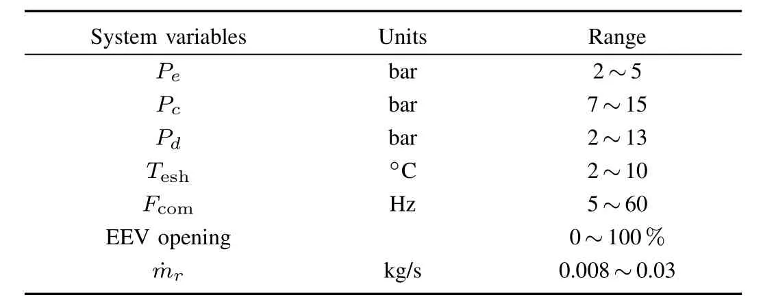
TABLE IIOPERATING RANGE OF THE VCC SYSTEM VARIABLES
The outer loop model is shown as(1).Then a PI controller is developed in this section and fine-tuned to determine the setting value of superheat for inner loop based on the MSS under current cooling load.The parameters of PI controller are shown in Table IV.

with Kp=1.0338,Tp=21.185,Td=8.6178.
For the inner loop,an N4SID model is first identified.The random inputs shown in Fig.5 are generated around a set of nominal operating conditions and subsequently implemented on the nonlinear VCC experimentalplatform.Fig.6 shows the identified N4SID model compared against the experimental data from the rig system,demonstrating the prediction capability of the identified inner loop model.
Based on the identified models,the MPC is designed,and the parameters and constraints are given in Table V.Experimental analyses and the performance comparison for the proposed energy efficient control(PI-MPC)and a normal controlstrategy(PI-PI)are carried out,both ofwhich are under the same outer loop control structure.

Fig.5 The random input signals.

Fig.6 Comparison of the outputs.
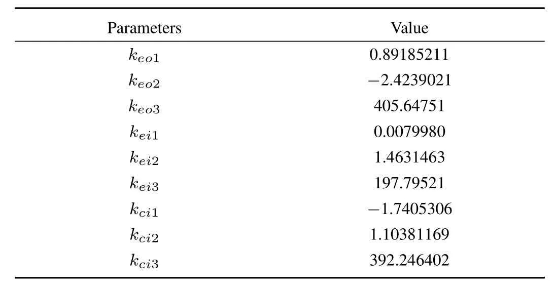
TABLE IIITHE PARAMETERS OF THE ENTHALPIES
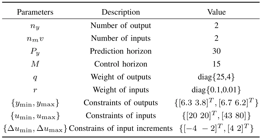
TABLE V THE PARAMETERS OF THE PROPOSED CONTROLLER
B.Evaluating Performance of the Proposed Control Strategy
In order to prove the energy efficiency of the proposed control strategy,the performances of the proposed PI-MPC structure and a normal PI-PI control structure are compared in this section.The normal PI-PI control structure consists of inner loop which has a VCC system model and a PI controller,and outer loop which is identical with the outer loop of the proposed controlstructure.Based on the identified inner loop model,a PI controller for performance evaluation of inner loop in normal control structure is designed first.By applying relative gain array(RGA)analysis,the I/O pairings,the fi ne-tuned gain,and integral time values are all included in Table VI.The experimentis carried outon the basis of the same outer loop structure in which the outer loop provides the same setting values for both MPC and PI controllers of inner loop.The external environmental conditions are assumed to be consistent during the experimentperiod.The parameters of MPC are shown in Table V.

TABLE VI THE PARAMETERS OF THE PI CONTROLLER

Fig.7. The comparison of pressure difference of different controllers.
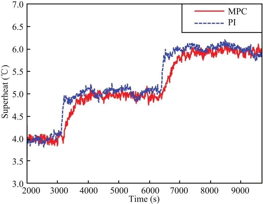
Fig.8. The superheat comparison of different controllers.
In this research,an increase in cooling demand occurred at time t=3180 s from 2 kw to 3 kw,and then it further increased from 3 kw to 4 kw at time t=6480 s.The PI controller of outer loop regulates rapidly the set point of superheat to new values.Then the controllers of inner loop drive both pressure difference and superheat towards the desired references shown in Figs.7 and 8,respectively.The PI controller shows better rising time while larger overshoot performance than MPC,which is because the proposed MPC has the capability to deal with the constraints and coupling issue.By analyzing the experiment results in this case,although the MPC controller needs longer response time than PIcontroller,low overshootperformance ofthe proposed MPC controller is demonstrated which ensures the safe operation of the VCC system.
Figs.9 and 10 display the input variable response curves for the two controllers.The cooling demands are satisfied by wider opening of expansion valve and lower compressor speed of MPC controller than PI controller.For the purpose of stable and safe operation,an operating range of the system variables is considered in Table II.The compressor speed of the PI controller at time t=6500 s exceeds 43 Hz,which demonstrates that MPC controller has more distinctadvantage than PI controller does in respect of dealing with constraints(Fig.9).
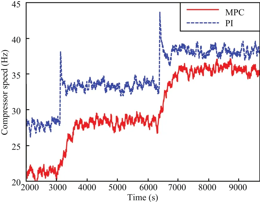
Fig.9. The random input signals.

Fig.10.The random input signals.
The COP curves of two controllers are shown in Fig.11 which verifies the effectiveness of the controllers.By comparing the MPC controller with PI controller,the COP for MPC controller is increased by 8%.This is because lower compressor speed for MPC controller is required than that for PI controller according to the optimization of energy consumption in(15),which reduces the energy consumption as much as possible.In this case the proposed controlstrategy offers better tracking performance with constraints and energy efficiency of VCC system than the PI-PI control strategy.
V.CONCLUSION
This paper develops a multi-input multi-output energy efficiency control architecture to improve energy efficiency while meeting changing demands forcooling capacity.The architecture consists of inner loop and outer loop in which an analysis on the nonlinear relationship between MSS and cooling load is firstly carried out to obtain the setting value of superheat for the inner loop which can produce the maximal effect on the system performance.In the inner loop,the proposed MPC controller is applied to track the setting value of pressure difference and the superheat of the evaporator determined by the outer loop so that minimum energy consumption of VCC system is ensured.Experimental results confirm the energy efficiency and good trajectory tracking characteristics of the proposed control strategy.
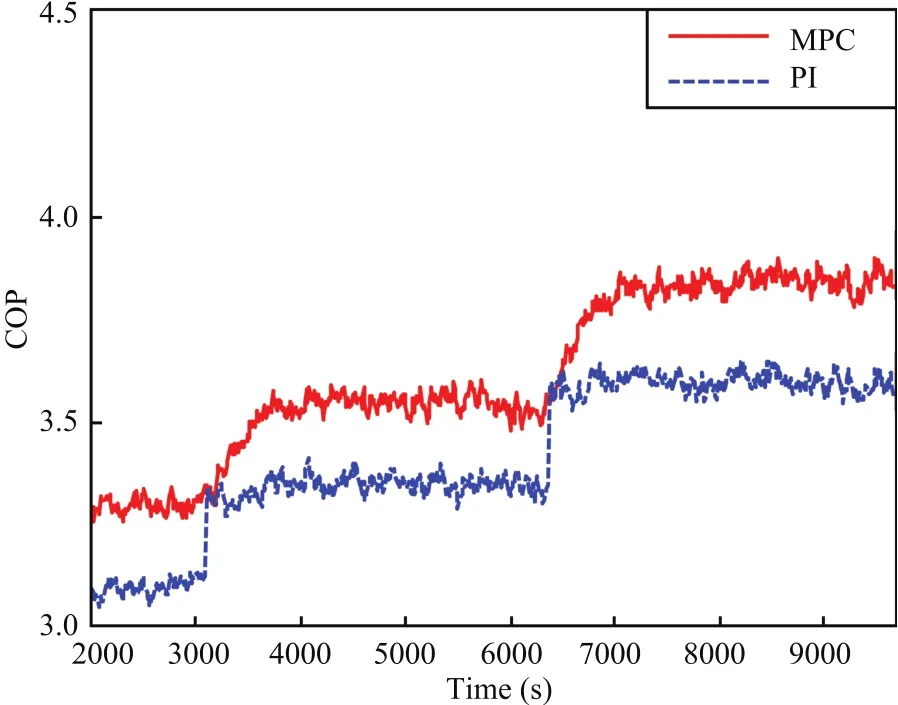
Fig.11.The random input signals.
杂志排行
IEEE/CAA Journal of Automatica Sinica的其它文章
- Iterative Learning Control With Incomplete Information:A Survey
- Fundamental Issues in Networked Control Systems
- Adaptive Neural Network-Based Control for a Class of Nonlinear Pure-Feedback Systems With Time-Varying Full State Constraints
- A Dynamic Road Incident Information Delivery Strategy to Reduce Urban Traffic Congestion
- Feed-Forward Active Noise Control System Using Microphone Array
- A Robust Reserve Scheduling Method Considering Asymmetrical Wind Power Distribution
