A Dynamic Road Incident Information Delivery Strategy to Reduce Urban Traffic Congestion
2018-09-28LiangQiMemberIEEEMengchuZhouFellowIEEEandWenjingLuanStudentMemberIEEE
Liang Qi,Member,IEEE,Mengchu Zhou,Fellow,IEEE,and Wenjing Luan,Student Member,IEEE
Abstract—Advanced information and communication technologies can be used to facilitate traffic incident management.If an incident is detected and blocks a road link,in order to reduce the incident-induced traffic congestion,a dynamic strategy to deliver incident information to selected drivers and help them make detours in urban areas is proposed by this work.Time-dependent shortest path algorithms are used to generate a subnetwork where vehicles should receive such information.A simulation approach based on an extended celltransmission modelis used to describe traffic flow in urban networks where path information and traffic flow at downstream road links are well modeled.Simulation results revealthe influences ofsome major parameters of an incident-induced congestion dissipation process such as the ratio of route-changing vehicles to the total vehicles,operation time interval of the proposed strategy,traffic density in the traffic network,and the scope of the area where traffic incident information is delivered.The results can be used to improve the state ofthe artin preventing urban road traffic congestion caused by incidents.
I.INTRODUCTION
T RAFFIC incidents are any non-recurring events including traffic crashes,disabled vehicles,roadway maintenance and reconstruction projects,and specialnon-emergency events,e.g.,ballgames,concerts,or any other events thatsignificantly affect roadway operations[1].They can cause a signifi cant capacity reduction of roadways.Traffic incident management(TIM)makes a systematic effort to detect,respond to,and remove traffic incidents.It aims to offer the rapid recovery of traffic safety and capacity,and leads to many measurable benefits,such as decreases in fuel consumption,incident duration,secondary accidents,and traffic jams[1],[2].
There are many traditional traffic control methods for TIM in highways,such as lane control[3],variable speed limitcontrol[4],and ramp metering control[5].So far,incident-based urban traffic congestion is mostly controlled and prevented through traffic flow diversion with the help ofthe traffic police.Such a strategy is unfortunately labor-intensive,inflexible,and costly.Intelligent transportation systems[6]-[8],such as advanced traveler information systems(ATIS),can be employed to improve the network efficiency via direct or indirect recommendation of alternative routes[9].Real-time traffic information can be sent to drivers through two main kinds of devices:in-car[10]and road-side devices[11].The type,such as radio GPS-navigators and Google Maps,helps drivers make sensible routing decisions at bifurcation nodes of the network.However,there are some disadvantages with these kinds of devices.On one hand,drivers who are familiar with the traffic conditions in a network may not use such agencies and thus optimize their individual routes based on past experiences.On the other hand,incident information is only useful to a finite number of selected drivers near the incident,and useless to others.The second kind of devices can be used to deliver information on major traffic events(e.g.,incidents and congestion)and reduce incident-based congestion or enhancing traffic safety.However,they are usually spatially and/or temporally limited and constrained in the amount of information delivered.Thus,to the best of our knowledge,we find no intelligent strategies that can decide which drivers should be informed of a particular traffic incident.Recently,the proliferation of mobile communication technologies and devices such as smartphones and on-board units of connected vehicles makes it possible to construct an accessible and cost-effective platform for public-sector Traffic Operation Centers to deliver location-based and personalized traveler information in a timely fashion[12].In this work,we design a new strategy to deliver incident information to a finite number of selected drivers in urban areas.The Dijkstra’s algorithm is used to generate a subnetwork where vehicles can receive the traffic incident information.This helps reduce incident-induced congestion at a manageable communication cost.Simulations are conducted to give a quantitative result regarding traffic congestion reduction with the proposed strategy.
Many simulation models are proposed to model traffic jam formation due to incidents.Wrightand Roberg propose an incident-based jam growth model in[13]and discuss the impactofthe length ofthe channelized partofroads and stopline width assignment on jam formation.Roberg et al.develop several alternative strategies in[14]to prevent gridlock of a network and dissipate traffic jams once they have been formed.Long et al.[15]extend a cell transmission model(CTM)and apply it to simulate incident-based jam propagation in two-way rectangular grid networks.They also propose control strategies for dispersing incident-based traffic jam and evaluate their efficiency[16].CTM-based models can depicttraffic flow at downstream road links well.However,the aforementioned simulation models do notcontain any path-related information when studying travelers’detour behaviors and the incidentinduced congestion formulation.In this work we further extend the CTM,build a modelto simulate incident-based traffic jams in urban areas and illustrate the effectiveness of our proposed strategy.
The rest of this paper is organized as follows.Section II reviews the related work.Section IIIpresents some definitions about the traffic network.Section IV gives traffic incident information delivery strategies.In this section,given some assumptions regarding traffic flow routing choices,a traffic flow sub-network is generated based on Dijkstra’s algorithm,and traffic flow in the network is modeled by an extended CTM.Section V gives a case study and evaluates the effectiveness of the proposed detour strategies via simulation.Section VI concludes this paper.
II.RELATED WORK
A.Traffic Incident Management(TIM)
There are many traditionaltraffic controlmethods for TIM.For example,lane control systems[3]deploy lane control signals in the contextof lane closure.They are used to manage traffic at a lane level to facilitate a smooth lane change by informing drivers aboutan impending bottleneck.Variable speed limitcontrol[4]in highways is verified to be able to increase work-zone throughputs and decrease total vehicle delays.Traffic signals aton-ramps of freeway[5]can help manage the traffic inflow rate and reduce lane-blocking incident-induced traffic congestion.These methods are suitable for TIM in highways.So far incident-based urban traffic congestion is mostly controlled and prevented through traffic flow diversion with the help of traffi c police,which is unfortunately laborintensive,inflexible,and costly.Traffic lightcontrol[6]atroad intersections is regarded as a major strategy to guarantee the safe crossing ofconflicting streams ofvehicles and pedestrians and lead to efficientnetwork operations.They are suitable for non-saturated and stable traffic conditions.However,changing conditions in a non-predictable way such as an incident may lead to the invalidation of the aforementioned traffic light control strategies,and causes unexpected congestion.Some intelligentsystems have recently been designed for preventing incident-induced traffic congestion[17],[18].In such systems,ban signals are used to notify road users of a ban situation that might not be readily apparent[19]-[21].
B.Dynamic Traffic Assignment(DTA)
DTA is used to assign time-varying traffic flow to different highways given the vehicular demand and certain behavioral rules[22].It consists of two components:a travel choice principle and a traffic-flow component.The former models how travelers decide whether to travel or not[22],and if so,how they select their routes,departure time,modes,and destinations.The latter depicts how traffic propagates inside a transport network.DTA is an important research area because of its a wide range of applications in real-time traffic control and management[23].In fact,DTA models are key components in developing sophisticated intelligent transportation systems(ITS)technologies such as advanced traveler information systems(ATIS)[24]and advanced traffic management systems(ATMS)[25].In ATIS,DTA models can determine the best route and departure time and provide some anticipatory traffic information for travelers based on a forecasted traffic pattern.
DTA models can be developed by either an analytical[26]or simulation-based approach[27].DTA problems can be formulated analytically in terms of mathematical problems[23],[28],such as mathematical programming[29],optimal control[30],and variational inequality problems[31].Most prior studies focus on determining in advance the solution properties of the models,such as solution existence and uniqueness.The simulation approach focuses on enabling practicaldeploymentof the DTA models for realistic highway networks,their applicability to real-life highway networks,and their ability to adequately capture traffic dynamics and microscopic driver behavior such as lane changing.However,a simulation-based approach cannot guarantee the solution properties of the model in general[23].
DTA problems are formulated as both path-based[31],[32]and link-based models[28].An important feature of the former is that the path set has to be explicitly defined and can range from medium to large-sized networks.Hence,for large-scale network applications,path enumeration has not been used to obtain the path set.Link-based models can avoid path enumeration in the solution procedure,and hence can be applied to large-scale networks.However,they do notcontain path-related information and cannot capture certain realistic traffic dynamics such as dynamic traffic intersections across multiple links.
The commonly adopted travel choice principle in DTA is the dynamic extension of Wardrop’s Principle called the Dynamic User Optimal(DUO)principle[23],[31].This principle assumes that travelers select their routes and/or departure times to minimize their travel costs such as travel time.Mostexisting planning and managementprocedures are developed with this notion.Virtually all network planning models adhering to Wardrop’s principle require the following strong assumptions:1)travelers know the travel time on all routes,and 2)travelers are able to select the paths costing the shortest travel time.While these assumptions may be reasonable in a static network,they are questionable for real-world networks because they are dynamic and can be highly stochastic.The current research is not presented as an operationalmodelforactualapplications.Forexample,we can deliver the incident information to the corresponding traveler if we know the path of each vehicle.However,we do not know such path information,and in this case we should design incident delivery strategy to travelers to deal with the cases in which an incident takes place.
C.Advanced Traveler Information Systems(ATIS)
ATIS are any systems that acquire,analyze,and present information to assistsurface transportation travelers in moving from theirstarting location(origin)to theirdesired destination.Relevant information may include locations of incidents,if any,weather and road conditions,optimal routes,recommended speeds,and lane restrictions[24].ATIS are considered a powerfultoolto enhance travelers’experience[33].ATIS are also claimed to be useful under recurrent network congestion as they reduce the uncertainty oftravelers with respectto travel time[33].Moreover,they are useful for travelers who are unfamiliar with the network(e.g.,tourists),as well as for all travelers when the network is temporarily affected by some significant disruptions and/or by unexpected or non-recurrent traffic conditions[34].Recently,the proliferation of mobile communication technologies and devices such as smartphones and on-board units of connected vehicles makes it possible to construct an accessible and cost-effective platform for publicsector Traffic Operation Centers to deliver location-based and personalized traveler information in a timely fashion[12].Our work lies in the scope of the ATIS when itselectively delivers incident information to a finite number of selected drivers but not all vehicles.The effectiveness is verified through a simulation approach.
D.Cell Transmission Model(CTM)
Daganzo[35]proposes a CTM to simplify the solution scheme of the Lighthill-Whitham-Richards(LWR)model[36],[37]such that it can be used to depict the road link traffic which is consistent with the kinematic property of traffic flow.The CTM has been used to accurately describe realistic highway traffic.Daganzo’s original development of the CTM is mainly intended to provide transportation planners with another way of predicting traffic behavior for a given roadway section.Researchers have employed the CTM in many real-world transportation applications such as dynamic traffic assignment[38],[23],signal control[39]-[41],ramp metering[42],[43],and traffic prediction.The advantage of this approach is that traffi c dynamics such as queue spillback and traffic interaction across links can be captured.The CTM has been used in the estimation of traffic flow density[44]-[46]and other traffic state variables such as flows and space-mean speeds[47].Long et al.[15]extend the CTM and apply it to simulate incident-based jam propagation in two-way rectangular grid networks.The interface of vehicles conducting different turns at urban road links can be well described[15].They also propose control strategies for dispersing incident-based traffic jams and evaluating their efficiency[16].The above cell-based simulation models do not contain any path-related information when studying incidentinduced congestion formulation.In this work we furtherextend CTM[15]to simulate travelers’detour and incident-based traffic jams in urban areas and illustrate the effectiveness of our proposed incident information delivery strategy.
III.BASIC NOTATIONS
First,some basic notations are presented:R is a realnumber set,R+is the set of positive real numbers,N={0,1,2,...}is a natural number set,N+=N/{0}is the positive integer set,Nm={0,1,2,...,m}and N+m={1,2,...,m}where m∈N+.We consider a multi-destination network as a directed and connected graph G(N,A),where N={1,2,...,m}denotes the set of nodes and A denotes the set of links.Link a=(la,ha)∈A is a link with a tail node laand a head node ha.A(j)and B(j)are the set of links leaving node j and heading to node j,respectively.We give some definitions regarding a multi-destination traffic network G(N,A).Usually a path is composed of a sequence of links.We assume that there is atmostone link from a node to another.Thus,a path can be expressed by a sequence of nodes.We give the formal definition of a path as follows.
Definition 1:A pathσ1,m=(1,2,...,m)is defined as a sequence of nodes labeled from 1 to m,where(j,j+1)∈A,∀j∈,1 is its origin and m is its destination.The setof all paths in G is denoted asΓ.The set of all paths from node 1 to node m is denoted asΓ1,m.If(j,j+1)is a link in path σ1,m,we denote that(j,j+1)∈ σ1,m,else(j,j+1)∈/σ1,m;if j is a node in pathσ1,m,we denote that j∈ σ1,m,else j∈/σ1,m;andσjdenotes a path with node j as its origin.We define a connection between two paths asσ1,m= σ1,j+σj,m,where j∈ σ1,m.
Allconcepts in Definition 1 can be found in the graph theory in[48].
Definition 2:l:A→R+is a link length function,where l(j,j+1)is the length ofthe link(j,j+1);anddenotes the length between two nodes j and j+1 where=l(j,j+1)if(j,j+1)∈A,and=+∞if(j,j+1)/∈A.
Definition 3:L:Γ→R+is a path length function,where

whereσ=(1,2,...,m)∈Γ.
Definition 4:τ:(A,t)→ R+is a link travel-time function,whereτ(a,t)denotes the traveltime for a vehicle to pass link a when it stays at the tail of a at time t.denotes the time needed from nodes i to j.
Definition 5:T:Γ→R+is a path travel-time function,where

denotes the traveltime thata vehicle needs to pass pathσ∈Γ.
Definition 6:f:Γ→N+is a node-count function,where f(σ)=|σ|-1 denotes node count in path σ ∈ Γ.

T1,m=T()denotes the travel time to pass the timedependent shortest path with the fewest nodes from node 1 to node m;andis the setof alltime-dependent shortest path with the fewest nodes from 1 to m.Γ∗denotes the set of all time-dependent shortest path with the fewest nodes.
IV.INCIDENT INFORMATION DELIVERY STRATEGY
This section presents a dynamic strategy to deliver incident information to a finite number of selected drivers in urban areas in order to help them make detours.According to[13],[14],and[16],the boundary of incident-induced traffic jams has an approximate diamond shape in grid networks with the firstblocked junction as the center.We need to provide traffic incident information to drivers heading towards the blocked link.First,we make some assumptions regarding the traffic flow evolution.Based on them,we can simplify the network and focus on only those links where traffic flow is affected by the incident.
A.Drivers’Path Selection Assumptions
In urban areas,for a traveler going from an origin to a destination,there are usually severalpaths.Regarding the path which is most selected by drivers,we make the following assumptions.
Assumption 1:Time-dependent Shortest Path Selection:We assume that given two paths from an origin to destination,without any information regarding the traffic condition such as incident,drivers select the one requiring the least time.If two paths cost the same travel time,drivers will choose the one with the shortestpath.Formally given two pathsσ1,σ2∈Γ1,mwith T(σ1) < T(σ2),or T(σ1)=T(σ2)and L(σ1) <L(σ2),then drivers select path σ1from origin 1 to destination m.
Assumption 2:Fewest-node Path Selection:We assume that given two same-travel-time and same-length paths from the origin to destination,drivers usually select a path with fewer road intersections to prevent extra traffic delay induced by traffic signals.Formally given two pathsσ1,σ2∈ Γ1,mwith T(σ1)=T(σ2),L(σ1)=L(σ2)and f(σ1) < f(σ2),drivers select pathσ1from origin 1 to destination m.
Assumption 3:Equal Probability Selection:)If there are N same-travel-time,same-length and same-number-of-node paths from the origin to destination,the probability of each path to be selected is equal,i.e.,a driver has the probability of 1/N to select each path.
B.Sub-network Construction
Given a network G(N,A)and a link s=(ls,hs)where an incident happens and blocks the link,we adopt the Dijkstra’s algorithm to generate a sub-network G(N′,A′)which contains allpaths with each satisfying the following conditions:it is a time-dependentshortestpath from the origin to its destination hs;it has fewer nodes than other paths from the origin to hs;and it contains link s.The traffic fl ow in the sub-network could be affected by the incidenton s under Assumptions 1-3,because some vehicles are being driven to the blocked link.The detailed steps to obtain G(N′,A′)are shown as follows.

Algorithm 1 Generate a Sub-network G(N′,A′)Input:A network G(N,A)and a link s=(ls,hs)where an incident occurs.Output:A sub-network G(N′,A′).Step 1.Initialization Set S:={hs,ls};//S contains the nodes whose timedependent shortest paths to hs have been obtained Set R:=N-S,N′:={hs,ls},A′:={(ls,hs)}and σls:=s;Set Tj,hs:=+∝and fls,hs:=0;SetΓ∗1,m:= Γ∗ :={s}and Γ∗j,hs:=∅;Step 2.Calculation and update Select a node j∈R such that the paths from j to ls and then hs are the time-dependent shortest paths of those from a node in R to ls and then hs,i.e.,∃σk=(k,...,ls,hs)∈ Γ∗and(j,k)∈ A such that∀σk′=(k′,...,ls,hs)∈ Γ∗,j′∈ T and(j′,k′) ∈ A:T(σk)+ τj,k ≤ T(σk′)+ τj′,k′,L(σk)+lj,k ≤ L(σk′)+lj′,k′;For each pathσj f(σj):=f(σk)+1 ifσj=(j,k)+ σk.Ifσj is a time-dependent shortest path with the fewest nodes from j to hs,then Γ∗j ,hs:=Γ∗j,hs∪{σj};j,hs into N′,i.e.,N′:=N′+{r|r∈ σj};Put all links in each path σj ∈ Γ∗j,hs into A′,i.e.,A′:=A′+{(r,k)|(r,k)∈ σj};End If Step 3.Iteration Repeat Step 2 until S=N;Return Take node j out of R,i.e.,R:=R-{j};Put node j into S,i.e.,S:=S+{j};End If End For If there exists no node j′such that(j′,j) ∈ A,then Put all nodes in each pathσj∈ Γ∗
Assume that the number of nodes in N is n.For each node in N,all paths with the shortest distance from it to hsshould be computed.Therefore,the complexity of the algorithm of generating such a sub-network is O(n2).
C.Traffic Network Model Based on CTM
Daganzo[35]proposes a CTM to simplify the solution scheme ofthe Lighthill-Whitham-Richards(LWR)model[36],[37]such that it can be used to depict the road link traffic which is consistent with the kinematic property of traffic flow.This work extends CTM to model urban network traffic flow.The path-related information will be contained in the model when studying the incident-induced congestion formulation.We use a time-step method based on the extended CTM to simulate the formation and dissipation of incident-based traffic jams and evaluate the efficiency of the proposed control strategies.
As shown in Fig.1,each link a in the networks is divided into two distinct zones:downstream queue storage areas L,S and R where vehicles are organized into separate turning movements(left in L,straight in S,and right in R),and an upstream reservoir where the turning movements are mixed.Notice that there may be less than three storage areas,e.g.,the queue storage areas are composed of S and R where there is no left turn for the traffic outflow of link a.We assume that the upstream reservoir is composed ofλcells indexed from 1 toλ,and the channelized queue area occupies a cell indexed λ +1.We adoptφL,φS,and φRto denote the proportions of vehicles travelling in the left turning,straight,and right turning directions,respectively.Stopline width assignment variablesαL,αS,αR,respectively,denote the proportions of the segregated queue areas devoted to the left turning queue storage area,to the straightqueue storage area and to the right turning queue storage area.According to the definition,we haveφL+φS+φR=1 andαL+αS+αR=1.We adopt a“balanced”layout of stop line assignment[13]such that the stop line widths devoted to the straight and turning directions are in exactly the same ratio as the demands,i.e.,φL= αL,φS= αS,and φR= αR.
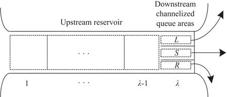
Fig.1. Link a in networks.
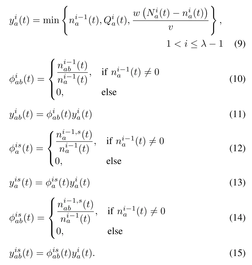
Note thattraffic rules willnotbe changed and the vehicles in the downstream queue areas will not change lanes.Using the network model,we design a network traffic simulation model based on the time-step method.Traffic flow formulation can be classified into the following categories:inflow of upstream reservoir of the origin and the other nodes(i=1),inflow of upstream cells(1<i≤λ-1),and inflow and outflow of channelized downstream queue area(i=λ).In the following equations,v(miles per hour)is the free flow speed and w(miles per hour)is the speed of all backward moving waves.yi(t)is the number of vehicles that enter cell i during time interval t,ni(t)is the number of vehicles in cell i before t,Ni(t)denotes the maximum number of vehicles that can be contained in cell i during t,and Qi(t)denotes the inflow capacity in cell i during t.More details regarding CTM can be referred to[35].The inflow formulation under normal traffic conditions,i.e.,without incidents,is presented as follows:
1)Infl ow of Upstream Reservoir From an Origin:Let da(t)denote traffic demand rate from an origin node lato link a in time interval t,dsa(t)traffic demand rate from node lathrough link a to link s attime t,φsa(t)and the proportion of vehicles entering link a at time t with the destination to s.The inflow of upstream reservoir of the origin can be calculated as

The number of vehicles that enter the first cell of link a in time interval t and choose b as the next link is calculated as

The proportion of vehicles that enter the first cell of link a and head to link s in time interval t is computed as

The number of vehicles that enter the first cell of link a in time interval t with the destination to s is calculated as

The number of vehicles that enter the first cell of link a in time interval t,choose b as the next link and head to s is calculated as

3)Inflow of Channelized Downstream Queue Area:The upper bound of inflow of the downstream queue area for vehicles travelling from link a to link b is computed as follows:

Because of interference between turning vehicles and straight vehicles[30],the total inflow of the channelized queues area can be formulated as follows:

The infl ow of each direction can be calculated as follows:

The proportion ofvehicles thatentercellλoflink a,choose link b as the nextlink,and head to link s in time interval t is computed as

where k=|A(ha)∩A′|.
The number of vehicles that enter cellλof link a,choose link b as the next link,and head to link s in time interval t is computed as

4)Outflow of Channelized Downstream Queue Area:yλ+1is defi ned as the outflow of the terminal cellλ.The outflow of the channelized downstream queue area can be calculated as follows:
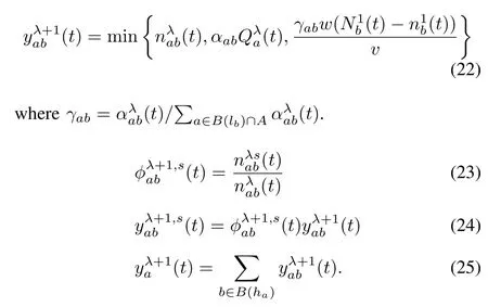
5)Inflow of Upstream Reservoir From a No-Origin Node:

where ua(t)denotes the inflow rate from node lathrough link a at time t.

where k=|A(ha)∩A′|and k1= φab(t)/P b∈A(ha)/A′φab(t).
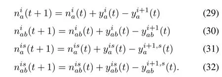
As a resultfrom the above formulae,the updated numberof vehicles contained in each cell is formulated as follows.For 1≤ i≤λ,we have
Traffic incidents are modeled by modifying the value of the corresponding flow capacity of the affected cells.(t)=0 if t belongs to the period with an obstruction on cell i.We assume that(t)and(t)are independent of time and cells’indices.Hence,they are constants denoted as(t)=Q and(t)=N,where N,Q∈R+.
Traffic jam size is used to describe the effectof congestion.A cellisjammed ifits density in the cellsofupstream reservoir or in any direction of the downstream channelized areas is greater than 0.9N[16],where N is the maximal number of vehicles that a cell in the upstream reservoir or an area in the downstream channelized areas can contain.The size of the traffic jam is described in terms of the total number of jammed cells.
D.Drivers’Detour Model
When drivers heading towards the incident-blocked link obtains information regarding the incident,they may detour at the following intersections along the path.In this section,we consider three detour strategies where the detour rates could be related to certain traffic conditions.Let s be a road link blocked by an incident.In the following discussion,αdenotes the proportion of vehicles heading to link s that will change their direction and release from a node along its path;βarepresents the proportion of flows that change their direction to the incident-blocked link and release link a’s head node.There are assumptions that we will adopt to defi ne the detour rate:
Assumption 4: Equal Detour Rate: If a vehicle in link aheading to the incident-blocked link s receives the incidentinformation and decides to detour, it has equal probability todetour at each of the following nodes on its path to link s.Formally, letσhabe the path of vehicles from the head nodeof link a to s, and let the proportion of vehicles that detour at a’s head node be βa=1/f(σha).
Assumption 5: Distance-related Detour Rate: If a vehicleheading to the incident-blocked link s receives the incidentinformation and decides to detour, its probability to detouris related with the distance to s, i.e., the detour probabilityis bigger when the distance is shorter. Formally, letσhabethe path of vehicles from the head node of link a to s; theproportion of vehicles detour at node a then equals

Assumption 6: 100% Detour: The proportion of vehiclesthat detour at a’s head node is equal to 100% when thereis another equal-length time-dependent path containing noincidental link from the a’s head node to s’s head node.
In the CTM model,givenα andβa,we first modify the number of vehicles in each cell as follows:


At downstream queue channel areas, the number of vehiclesis changed as follows:

We also need to change inflow of the upstream reservoirfrom an origin for the next time interval.(t)enters the1st cell, then α proportion of flows leading to link s willchange their direction immediately. Thus, we have

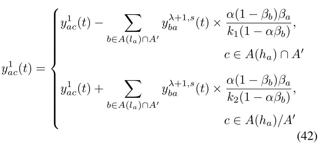
We also need to change inflow of the upstream reservoirof links that are not the origin for the next time interval.Suppose that(t)vehicles enter the 1 st cell from b.Then α portion of flows change their direction immediately.Suppose the outflow from link b∈ A(la)∩A′to s without any traffic incident information from equals y′.Then,after receiving the incident information, the amount of y′α vehicles will change their directions while′αβbvehicles change their directions and leave from linkb,and y′α(1- βb)change directions at upcoming nodes in the path. In the next link a,the number of vehicles that change their directions is y′α(1-βb)βa.Weuse(t)to to denote the outflows of theterminal cell λ of link a that choose link b as the next link andhead to link s in time interval t. Thus, we have the followingequations:

Given that

we have that
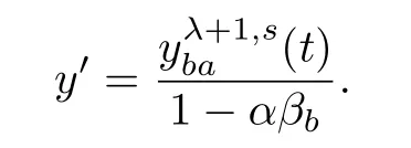
Replacingy′in(39),wehave

As a result, we change the inflow of the upstream reservoirof link a during each next time interval as follows:

Also, we change the following inflow value:
V.CASESTUDY
A.An Example to Construct a Sub-Network
We give a one-way grid network as an example as shownin Fig. 2 (a) where it is composed of one-way road links withadjacent rows or columns having opposite directions. Note thatthis kind of road networks is very common in major cities,for example, New York City. We install a single incident inthe network: a single incident occurs on link (33, 34) in thenetwork as shown in the figure. Note that in the grid network,the shortest paths are the time-dependent shortest paths.
According to Algorithm 1, for each node in G, we computeall the shortest paths leading to node 34 with (33, 34) as thelast link. After that, we obtain the following paths to generatethe sub-network.
Path1:(3,23,28,33,34);
Path2:(18,31,32,33,34);

Fig.2. A traffic network with an incident in(a)and the generated subnetwork in(b).
Path 3:(7,30,29,28,33,34);
Path 4:(14,42,37,32,33,34);
Path 5:(1,21,22,23,28,33,34);
Path 6:(20,21,22,23,28,33,34);
Path 7:(5,25,30,29,28,33,34);
Path 8:(1,21,26,31,32,33,34);
Path 9:(20,21,26,31,32,33,34);
Path 10:(16,41,42,37,32,33,34).
Thus,we have N′={34,33,28,23,3,32,31,18,29,30,7,37,42,14,22,21,1,20,25,5,26,41,16},A′={(33,34),(28,33),(23,28),(3,23),(32,33),(31,32),(18,31),(29,28),(30,29),(7,30),(37,32),(42,37),(14,42),(22,23),(21,22),(1,21),(20,21),(25,30),(5,25),(26,31),(21,26),(41,42),(16,41)}.After the above steps,the generated sub-network is shown in Fig.2(b).According to Assumptions 1-3,when a traffic incidenthappens,we only need to provide the incident information to drivers in the subnetwork.Drivers from other links of the network in Fig.2(a)will not head to the blocked link,and thus the incident information is useless for them.
B.Simulation and Results
Now we evaluate the effectiveness of the proposed strategy by employing MATLAB software through simulation.We first setspecific values forthe parameters in oursimulation.We set a single incidenton the 5th celloflink(33,34)in the network as shown in Fig.2(a).The corresponding values of the subnetwork are shown in Table I.In the traffic network in Fig.3,according to the special structure,the flow proportions for directions are set as:φT= αS=0.5 where φT∈ {φL,φR}.The analysis period of interest is divided into 2000 intervals(i.e.,2.78 h).The network is assumed to be empty initially.Traffic starts to enter the network from origins 1-20 at the first time interval.Several time intervals are required to allow the system to stabilize.The incidentoccurs at the t1=301st interval.Note thathere we do notconsider the effectof traffic light signal strategies regulating the traffic flow.This can be easily realized by modifying the value of the corresponding flow capacity of the affected cells.In the simulation,in order to keep the balance of the traffic flow,we set all inflows as well as all outflows of links to be equal.We have the value of inflow and outflow of the nodes.
With the simulation of our designed model,we study the traffic jam in the traffic network in Fig.2(b).Afterthe incident messages are delivered,drivers will then detour.We identify the influences of some important parameters,i.e.,the inflow rate,the detour rate of drivers,and the start time for providing traffic incidentinformation.We provide a sensitivity testof the following parameters as shown in Table II.
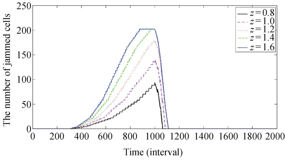
Fig.3. Congestion formulation and dissipation under no traffic control strategy when traffic incident is from the 300th to 1000th interval,and the proportion of traffic demand heading to the blocked link is p=0.1.
First,let z denote a constant traffic demand at origins,i.e.,∀t,a,z=da(t),and p denote the proportion of traffic flow heading to the blocked link s at origins.We study the effect of z on jam formation and dissipation if there is no traffic control strategy.The incident occurs at the 301st interval and is cleared at the 1000th interval.We set p=0.1.Some simulation results of congestion formation and dissipation are shown in Fig.3.We learn that when the traffic demand increases,the traffic jam forms more quickly.We have a result that if z≤1.3,the traffic jam can dissipate in 100 intervals(8.33 minutes).In the following simulation,we set the traffic demand z=0.8.
Then,we study the proportion of traffic demand at origins that head to the blocked link,with the results being shown in Fig.4.Under the situation where z=0.8,with a increase of p,the number of jammed cells grows sharply.There is little congestion when p is below 0.01.

Fig.4. Congestion formulation and dissipation under no traffic control strategy and the proportion oftraffic demand atorigins thathead to the blocked link is p=0.01,0.05,0.1,0.2,and 0.3,respectively,and z=0.8.
We further study the end time of the traffic incident and the results are shown in Fig.5.Under the traffic conditions wherez=0.8 and p=0.1,if the incident is cleared and traffic capacity of the blocked link is recovered in 200 intervals(16.67 minutes),the number of jammed cells can be kept below 10.

TABLE I PARAMETERS FOR THE CTM[16]

TABLE II PARAMETERS TO TEST

Fig.5.Congestion formulation and dissipation under no traffic control strategy and the incident is cleared at the 400th,500th,600th,700th,and 1000th intervals,respectively,where z=0.8 and p=0.1.
We study when to provide incident information to drivers in the traffic network in Fig.6.Under Assumption 4 and the traffic conditions z=0.8 and p=0.1,if the proportion of flows that change their direction to link s is 0.9,there is little congestion when we start to deliver the incident information in less than 100 intervals(8.33 minutes).Under Assumption 5,we have similar results as shown in Fig.7.
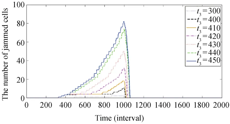
Fig.6. Congestion formulation and dissipation when traffic control strategy begins from the 300th,400th,410th,420th,430th,440th,and 450th intervals,respectively,under Assumption 4 and where z=0.8 and p=0.1.
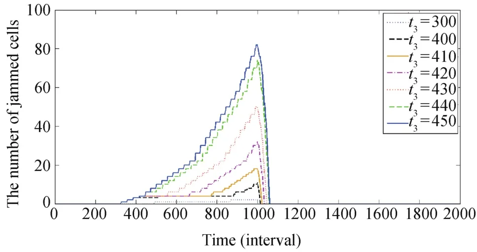
Fig.7. Congestion formulation and dissipation when traffic control strategy begins from the 300th,400th,410th,420th,430th,440th,and 450th intervals,respectively,under Assumption 5 and where z=0.8 and p=0.1.
We study the detour proportionαand have the results as shown in Fig.8.We can find there is little congestion formed whenα>0.8,which means that if more than 80%vehicles can obtain the incident information and then detour when z≤0.8 and p≤0.1,no traffi c jam occurs.Under Assumption 5,we have similar results as shown in Fig.9.Lastly we study the detour models given by Assumptions 4 and 5,respectively.Under the traffic conditions that z=0.8 and p=0.1,we set z=2.5,p=0.4,t3=450.The results in Fig.10 show that there is more congestion under the traffic detour strategy of Assumption 5 compared to that of Assumption 4.It means that drivers approaching the blocked link need to leave the path earlier to help reduce the traffic congestion induced by the incidents.

Fig.8.Congestion formulation and dissipation when the strategy begins from the 300th to 1000th interval,and the detour proportionα=0.5,0.6,0.7,0.8,and 0.9,respectively,under Assumption 4 and where z=0.8 and p=0.1.
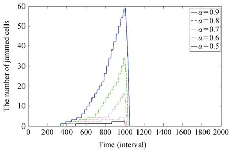
Fig.9.Congestion formulation and dissipation when the strategy begins from the 300th to 1000th interval,and the detour proportionα=0.5,0.6,0.7,0.8,and 0.9,respectively,under Assumption 5 and where z=0.8 and p=0.1.
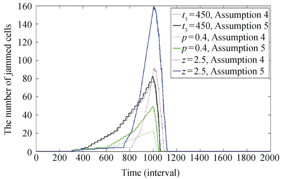
Fig.10.Congestion formulation and dissipation undertraffic conditions z=2.5,p=0.4,and when the traffic control strategy begins at t3=450,and under the two detour strategies of Assumptions 4 and 5,respectively.
We study a link set A′′and a constantη where the number of nodes from a link in A′′⊆ A′to link s is no more than η while the number of nodes from a link in A′-A′′to s is bigger thanη.We only deliver the incident information to drivers at road links in A′′instead of A′.Obviously,η represents the scope of area where incident information is delivered.Some simulation results are shown in Figs.11 and 12:whenα=0.95,we only deliver information to drivers in link(28,33)and(32,33)such thatatmostone cellis congested as shown in Fig.11.With the decrease ofα,when delivering the incident information to a larger scope of road links,we can have a better result with fewer jammed cells.
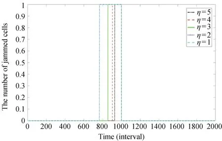
Fig.11.Congestion formulation and dissipation when f =1-5 under Assumption 5,and whereα=0.95,z=0.8 and p=0.1.

Fig.12.Congestion formulation and dissipation when f =1-5 under Assumption 5,and whereα=0.60,z=0.8 and p=0.1.
VI.CONCLUSIONS
This paper presents a new strategy,which provides incident information to drivers and helps them make detours in urban areas.Traffic incident information is only transmitted to the affected vehicles thathead towards the blocked link created by the incident.These vehicles are in a sub-network that can be generated by the Dijkstra’s algorithm.Simulations are done to testthe effectiveness ofthe proposed strategy.The CTM-based model is used to estimate the congestion and promote the implementation of our strategy.Future work should consider realworld traffic conditions when differentlinks have different traffic density.We also need to design algorithms to accurately estimate the time for vehicles to pass road links,and thus,obtain the time-dependent shortest path.
杂志排行
IEEE/CAA Journal of Automatica Sinica的其它文章
- Iterative Learning Control With Incomplete Information:A Survey
- Fundamental Issues in Networked Control Systems
- Adaptive Neural Network-Based Control for a Class of Nonlinear Pure-Feedback Systems With Time-Varying Full State Constraints
- Feed-Forward Active Noise Control System Using Microphone Array
- Energy Efficient Predictive Control for Vapor Compression Refrigeration Cycle Systems
- A Robust Reserve Scheduling Method Considering Asymmetrical Wind Power Distribution
