Collinear micro-shear-bands model for grain-size and precipitate-size effects on the yield strength
2018-09-19YikeQiuPengZhngLifeng
Yike Qiu, Peng Zhng, Lifeng M,*
ab S&V Lab, Department of Engineering Mechanics, Xi’an Jiaotong University, Xi'an 710049, China
Xi'an Thermal Power Research Institute Co., Ltd., Xi'an 710032, China
Keywords:Collinear micro-shear-bands model The Hall-Petch relationshipprecipitate Size effect
ABSTRACT Numerous experimental evidences show that the grain size may significantly alter the yield strength of metals. Similarly, in-strengthened nickel-based superalloys, the precipitate size also influences their yield strength. Then, how to describe such two kinds of size effects on the yield strength is a very practical challenge. In this study, according to experimental observations, a collinear micro-shear-bands model is proposed to explore these size effects on metal materials’yield strength. An analytical solution for the simple model is derived. It reveals that the yield strength is a function of average grain-size or precipitate-size, which is able to reasonably explain size effects on yield strength. The typical example validation shows that the new relationship is not only able to precisely describe the grain-size effect in some cases, but also able to theoretically address the unexplained Hall-Petch relationship between the precipitate size and the yield strength of nickel-based superalloys.
In 1950s, based on the experimental measurements of the yield strength of iron and steels at ambient temperature and at low temperature, Hall [1] and Petch [2] first found that the initial yield point, σy, scale with the average grain size, d:
where σ0and kHPwere specified as the material constants. This so-called Hall-Petch relationship was soon observed in other materials [3]. For instance, the grain-size effect was recognized in single Mo and W crystals during indentation tests [4], in twisted Cu wires [5] and thin flexuous foils [6] during tensile tests as well as in Ni, Au, Cu, and Al micro-pillars [7-9] during compression tests etc. One of theoretical underpinnings of the Hall-Petch relationship is the model of dislocation pile-up proposed by Eshelby [10], which suggests that yielding is to take place when the stress concentration at the head of a dislocation pile-up reaches the threshold value. Li and Chou [11]systematically reviewed the role of dislocations in the Hall-Petch relation in terms of pileups of different types of parallel straight dislocations and circular dislocation loops. They also predicted the similar form as Eq. (1) based on the model of grain boundary ledges that serve as dislocation sources at yielding.
In addition to the grain-size effect, the precipitate-size effect was also observed in precipitation-hardened alloys. One kind of these alloys are the-strengthened nickel-based superalloys. In the past, numerous research has been conducted on these superalloys. These studies have uncovered that the yield strength of precipitation-hardened nickel-based superalloys was intimately related to the volume fraction, size, and distribution of the γ′precipitates [12-14]. For example, the work of Oh and Han [15]on the variation of the critical resolved shear stress (CRSS) with the γ′precipitate size revealed that the CRSS was proportional to inverse square root of theprecipitate size in the overaged state. Zhang et al. [16, 17] investigated the influence of theprecipitate size on the yield strength of a directionally solidified nickel-based superalloy and obtained the results that plastic deformation was accomplished mainly by pairs ofdislocations cutting through theprecipitates instead of wrapping around precipitates (see Fig. 1), and its yield strength also seemed to be proportional to inverse square root of theprecipitate size at 650 °C. These results suggest that with respect to the influence of theprecipitate size on the yield strength of nickel-based superalloys, a Hall-Petch relationship might also exist.
However, it has been found that the Hall-Petch relationship is not suitiable for some materials in the literature [18-24]. Instead, a power-law formula has been proposed:

wherenis the fitting parameter for the grain-size exponent that widely scatters from 0.2 to 1. Following this formula, it has been found with experimental data fitting that n varies with regards to different metal materials: Christman [18] found that n should be 1/3 for the face centered cubic (FCC) metals and varied between 1/2 and 0.9 for body center cubic (BCC) metals. Korte and Clegg[19] claimed that there would be less grain-size effect in those stronger material, and the range of n should be around 0.5 or less for FCC metals, 0.6 to 1 for BCC metals, and approximately 0.2 or even lower for ceramics. Meanwhile, the theoretical estimates for the grain-size exponent were intensively explored.Bragg [20] initially derived that n=1. Baldwin [21] intended to use the model of single crystals to support that n=1/3, and Conrad[22] proposed thatn=1/4 based on the mean slip distance model. More recently, higher order crystal models have been studied, and a stronger grain-size effect on the yield strength was predicted. For instance, Evers et al. [23] obtained the grain-size exponent of 1.19 through the crystal plasticity model. Counts et al. [24] derived the grain-size exponent of 1.31 from nonlocal crystal plasticity model. After a simple survey, it can be found that: (i) The Hall-Petch relationship has a wide application [25]but it has limitation for some materials; (ii) The grain-size exponent in the revised power-law formula Eq. (2) is too disperse, which also makes the physical meaning of the formula dubious. Moreover, there still lacks a convincing formula to explain both the grain-size andprecipitate-size effect on yield strength.
The aim of this study is to explore two kinds of size effects on the yield strength of metal materials with a collinear microshear-bands model, which includes grain-size effect in pure metals and precipitate-size effect in nickel-based superalloys.We intend to find a rational relationship, which should not only be able to describe size effects on yield strength but also have a clear physical meaning.
The formulation of a horizontal embedded shear band of length 2l in an infinite plane is available in the book by Hills et al. [26]. The induced shear stress of the point x on the shear band due to a single dislocation with Burger’s vector located at the pointon the same shear band in local coordinates can be described in the following equation:

where μ is the shear modulus, υ is Poission’s ratio. Then, the shear stress at the pointxdue to a continuous distribution of dislocations along the whole shear band is then given by

where ρ (ξ), the dislocation density, is

Now considering the case of multiple horizontal embedded collinear straight shear bands of arbitrary length in an infinite plane, the induced stresses at the pointxon shear band due to the dislocation located along the trace of shear bands in local co-ordinates can be described in the following equation:
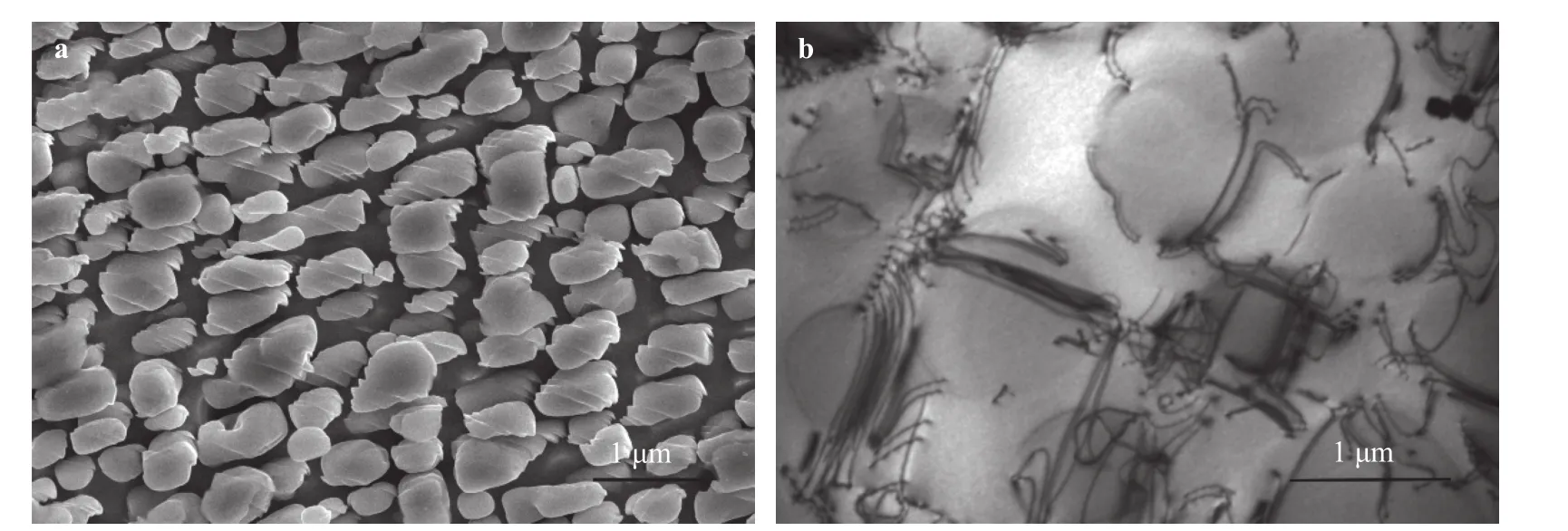
Fig. 1. Images showing the deformation microstructures in M4706 after tensile deformation at 650°C: a γ′ particles within shear bands; b pairs of a/2〈110〉 dislocations [16].

where aJand bJdenote the endpoints of the J-th shear band.
The grain-size effect of pure metals and the precipitate-size effect of nickel-based superalloys look different, but they may have the same physical mechanism: dislocation pile-up mechanism. Thus these two different experimental observations will be addressed with an identical model as the following.
Consider a two-dimensional elastic solid consisting of an infinite row of collinear micro-shear-bands embedded in uniformly sized, square cells, representing grains orparticles, under a remote applied shear stressand an internal friction,as shown in Fig. 2. Continuum dislocation pile-up description of the micro-shear-bands of length 2din the cells is considered.The thickness of cell boundary is 2a.
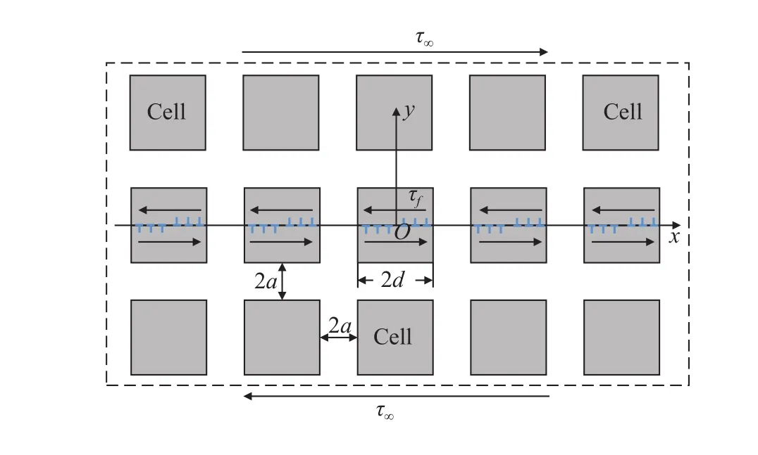
Fig. 2. An infinite row of collinear micro-shear-bands in the infinite matrix under the remote shear stress and the resistance internal friction: when a is very small compared to d, this model can be used to represent the close-packed grains; while if the scale of a is similar with d, this model can be used to explore the size effect of particle of Ni-based superalloys.
Following the distributed dislocation technique for multiple collinear straight shear bands of arbitrary length, we may obtain the shear stress at the pointxinduced by the distribution of dislocations along the all micro-shear-bands as

In terms of above expression, the influence of external shear stress τ∞and internal friction τf, the equilibrium equation for the dislocation distribution along the micro-shear-bands will be:

Assuming that the external shear stress τ∞and the internal friction τfare uniform, then the dislocation density ρ(ξ) will be a periodical function, thus Eq. (8) can be rewritten in the form as:

Equation (9) is the equilibrium equation of distributed dislocation for the infinite row of collinear micro-shear-bands. It should be explained that, the external applied shear loadin Eq. (9) actually equals the yield shear strength of the material.
The nature of singularity of the solution for the dislocation density at the both ends of the micro-shear-bands remains unaltered under arbitrary loading, and is governed by the singular integral equation given in Eq. (9). By following Leibfried’s method [27], Eq. (9) may be rewritten in the form as:

By using the series expansion formulait follows that

Since the dislocation density function is an odd function,namely, ρ (x)=-ρ(-x), thus Eq. (11) can be simplified as:

Further, by using the trigonometric formula

Eq. (12) can be rewritten as:

For convenience, by lettingbecomes:

The solution of Eq. (15) can be given as [27, 28]:

whereCis a constant to be specified. As the dislocation density function is an odd function, namely, and from Eq.(16), it gives

Hence the exact solution of dislocation density functionρ(x)can be finally derived as

The relationship of the stress intensity factor KIIat microshear-band tips dislocation density relates to function ρ (r) was given by Hills et al. [26]:

whereris measured in the negativexdirection at the right hand of any micro-shear-band. Equation (19) is quite similar to the form of the stress intensity factor of an infinite row of collinear cracks under the load of remote shear stress by Irwin [29] and Koiter [30], respectively, using Westergaard stress function and the method based on the Muskhelishvili formula. The main difference here is the presence of the internal friction τfin Eq.(19).

According to the theory of plasticity, Eq. (20) can be converted into the expression of conventional yield strength as Eq. (1)as

In this section, some degenerate and typical cases will be given to show the application of the new result Eq. (21).
(a) Yield strength of metals with stiff grain boundary: no interaction between grains
In iron and steel materials at ambient temperature, the stiff intergranular iron carbides are embedded within grain boundary, which may largely reduce the interaction between grains.Thus, the interaction between the micro-shear-bands will decrease. It can be approximately simulated with an isolated micro-shear-band case. Then the yield strength for this case can be attained by lettinga→ ∞ in Eq. (21) as

From Eq. (22), it can be found that the new formula automatically degenerates to −1/2 the classical Hall-Petch relationship.This degenerate case may imply that for the materials with stiff grain boundary, the yield strength can be roughly described with the classical Hall-Petch relationship.
(b) Yield strength of metals with large size grains
Similarly, compared to the thickness of the grain boundaries 2a, if the grain-size 2d is large enough in Fig. 2, i.e. d/a→ ∞, the conventional yield strength of bulk materials σ0can be degenerated from Eq. (21) as:

This case implies when the grain size is pretty large, the material yield strength is mainly from the internal frictional resistance to dislocation motion. These two degenerate cases can partially prove the validity and reliability of this model and solution Eq. (21).
In the following, the application of the present result Eq. (21)for the grain-size effect of aluminum and copper will be discussed.
Traditionally, the Hall-Petch relationship [1] is a statistical law for metal materials. Each parameter should have a clear physical meaning. For example,in Eq. (1) represents an internal friction [3]. However, when it is used to describe the grainsize effect for some concrete materials, unexplainably, the fitting parameter for the internal frictional forcein the Hall-Petch relationship could be negative. This clearly conflicts with its physical meaning. A typical example of metal is pure aluminum [31,32]. Using experimental data in [31, 32], the fitting parameterfor the Hall-Petch relationship is given in Table 1. In order to deal with this dilemma, the formula Eq. (21) is employed. In Eq.(21) the grain boundary thickness should be considered. Typically, the thickness of the grain boundary is widely accepted as 1 nm, thus here we set a=0.5 nm. The original experimental data and the fitting curves are plotted as shown in Fig. 3(a)-3(c), and the fitting parameters and the correlation coefficientR2are sum-marized in Table 1. Compared with the fitting curve of the Hall-Petch relationship, though the fitting precision of Hall-Petch relationship is quite high, the fitting parameterobtained for Eq.(21) is positive, which is an acceptable result. It can be observed from Fig. 3 that Eq. (21) is capable of precisely describing the grain-size effect. At the same time, it provides an acceptable physical explanation for grain-size effect of metal materials.

Table 1 Fitting Parameters for pure aluminum.
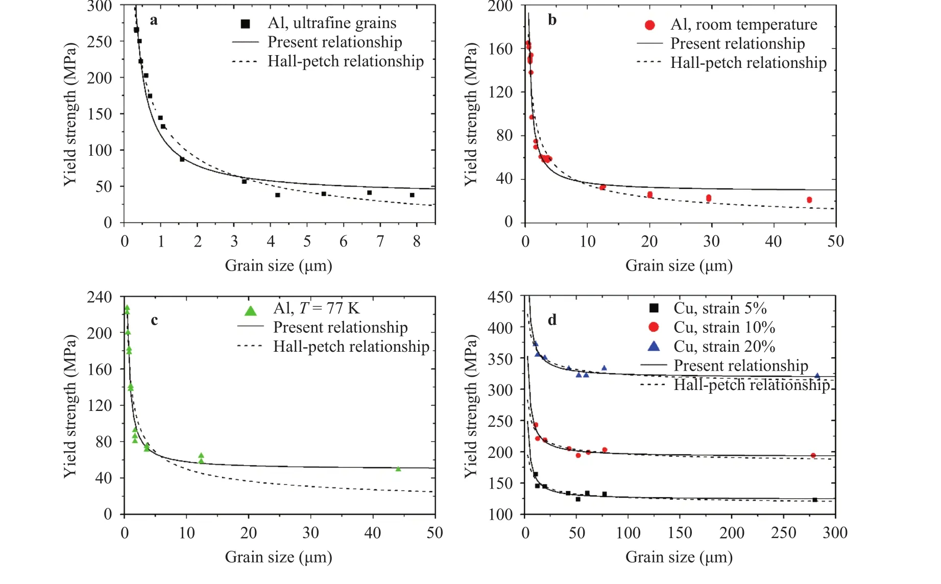
Fig. 3. Fitting curves for pure aluminum and copper: a tensile experiment data for ultrafine grained aluminum produced by ARB and annealing [31]; b tensile experiment data for aluminum at room temperature [32]; c tensile experiment data for aluminum at 77 K [32]; d tensile experiment data for copper at low temperature [33].
To further testify the validity of Eq. (21), some typical experimental data for pure copper at low temperature [33] are employed, which will be respectively fitted with the formulae of Hall-Patch relationship Eq.(1) and present relationship Eq. (21).Here we also seta=0.5 nm. The original experimental data and the fitting curves are shown in Fig. 3(d), and in Table 2 the fitting parameters and the correlation coefficientR2are summarized.Compared with the fitting curve of the Hall-Petch relationship,the present relationship in Eq. (21) is closer to the experimental observation.
These two typical examples can partially prove that the proposed model in this study is able to precisely describe the grainsize effect of metal materials. More importantly, it is able to provide a solid physical explanation for each parameter.
In the model of a row with infinite collinear γ′particles embedded in the γ matrix as shown in Fig. 2, the volume fraction of γ′particle can be expressed asd3/(a+d)3. For the nickel-based superalloys, the volume fractionfof γ′particle, which only depends on annealing temperature, remains unchanged with varied size of the γ′precipitate [34]. Then we have


Table 2 Fitting Parameters for pure copper.
To testify the validity of Eq. (24), typical experimental data for-strengthened nickel-based superalloys with high volume fraction at room temperature [35] are employed, which will be fitted with the formulae of present relationship Eq. (24). The original experimental data and the fitting curve are shown in Fig. 4, and in the Table 2 the fitting parameters and the correlation coefficientR2are summarized. It can be seen from the curve that the Hall-Petch relationship also exists in nickel-based superalloys.
In this study, to explore the influence of grain-size and precipitate-size on metal materials’ yield strength, a simple model of collinear micro-shear-bands has been proposed. Then, a new analytical expression for these two kinds of size effects on yield strength has been derived. This model is able to provide a reas-onable explanation for both grain-size and precipitate-size effects on the yield strength. Its validity has been testified with several typical examples, which shows that the new expression can precisely reflect these two kinds of size effects. In addition, the unexplained Hall-Petch relationship betweenprecipitate size and the yield strength of nickel-based superalloys has been addressed.

Table 3 Fitting parameters for Ni-based superalloys with high volume fraction.
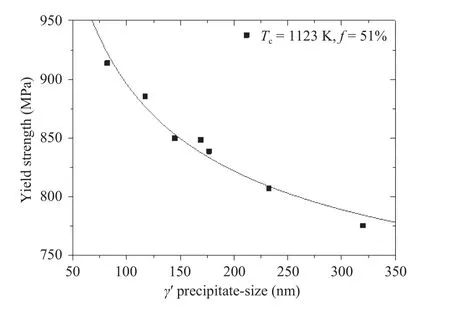
Fig. 4. Fitting curves for experimental data of the yield strength of nickel-based superalloys with high volume fraction [35].
Acknowledgments
This work is partially supported by the National Natural Science Foundation of China (41630634) and the China Postdoctoral Science Foundation (2017M623213).
杂志排行
Theoretical & Applied Mechanics Letters的其它文章
- Estimation of the effective properties of two-dimensional cellular materials:a review
- A data-based CR-FPK method for nonlinear structural dynamic systems
- On the interaction between bubbles and the free surface with high density ratio 3D lattice Boltzmann method
- Principal and internal resonance of rectangular conductive thin plate in transverse magnetic field
- Piezoelectric energy harvesting from flexible delta wings
- Dynamic rupture of metal sheet subjected to laser irradiation and tangential subsonic airflow
