Scheme design of the CHANG’E-5T1 extended mission
2018-07-24LeiLIUChunyangHU
Lei LIU,Chunyang HU
aBeijing Aerospace Control Center,Beijing 100094,China
bSchool of Economics,Nankai University,Tianjin 300071,China
KEYWORDS CHANG’E-5T1 mission;Extended mission;Flight scheme;Libration point;Lunar exploration;Trajectory design
Abstract Flight schemes for the CHANG’E-5T1 extended mission are investigated in this paper.In the flight scheme and trajectory design,the remaining propellant of the CHANG’E-5T1 mission is utilized.The CHANG’E-5T1 mission is firstly introduced with feasible flight goals derived based on the terminal trajectory and satellite status.The flight schemes are designed to include a lunar return and the libration points in the Sun-Earth/Moon and Earth-Moon systems,with an emphasis on the Earth-Moon triangle libration point thus far unexplored.Secondly,three schemes are proposed for the CHANG’E-5T1 extended mission with different flight goals.The direct libration point orbit transfer and injection method is adopted to solve the issue in the transfer trajectory design.Furthermore,an innovative concept is proposed to transfer from the Earth-Moon collinear libration point to the triangle point using the Sun-Earth/Moon libration point.Finally,the merits and drawbacks of the three schemes are discussed in terms of flight time,control energy and frequency, flight distance,and goal value.As a result,the scheme including a lunar return and the Earth-Moon L2 libration point is selected for the CHANG’E-5T1 extended mission.A flight to the Earth-Moon libration point is achieved,replicating the achievement of the ARTEMIS mission.©2018 Chinese Society of Aeronautics and Astronautics.Production and hosting by Elsevier Ltd.This is anopenaccessarticleundertheCCBY-NC-NDlicense(http://creativecommons.org/licenses/by-nc-nd/4.0/).
1.Introduction
China’s Lunar Exploration Program consists of three major operational phases:lunar orbital,soft-landing and rover,and sample return;each precedent phase technically paves a way for missions of the next phase.The first two phases were completed by the CHANG’E-1,which marked the country’s entry into the exclusive lunar exploration club,1,2and the CHANG’E-2 and CHANG’E-3 probes,which completed the predefined missions and a number of additional innovative exploration activities,3–6specifically, the CHANG’E-2 extended mission to the Sun-Earth Libration Point(SELP)and the CHANG’E-2 flyby of the Toutatis asteroid.In addition,CHANG’E-3 performed an unmanned lunar softlanding and rover mission in December 2013.7,8The third phase of lunar exploration in China started with a reentry test executed by the CHANG’E-5T1 in the second half of 2014.
The CHANG’E-5T1 spacecraft is composed of a service module and a reentry module.When the scheduled mission is completed,some propellant in the service module remains unused.As a result,the primary concern of the mission team is how to use the remaining propellant to accomplish some extended missions.To achieve this goal,the mission and trajectory will have to be designed with the constraint of the propellant taken into consideration.
This paper presents three schemes for the CHANG’E-5T1 extended mission with different flight goals and trajectories.As a Libration Point(LP)appears in all the three schemes,mathematical models are built to control the trajectory to and from an LP.Based on the widely-used invariant manifold,9–12Lo and his team innovatively proposed the concept of interplanetary superhighway,and designed a low-energy transfer trajectory for the Genesis mission,13–15demonstrating the value of the invariant manifold in low-energy trajectory design as a prevalent design method.Go´mez,Howell,and others also contributed to the theory and application of the invariant manifold.12,16The invariant method has also been used in studies of transfer trajectories between two threebody systems.Canalias and Masdemont investigated lowcost and even natural transfers between the Sun-Earth(SE)and Earth-Moon(EM)Lissajous LP orbits.17,18However,by adopting the invariant manifold in trajectory design,the LP orbit needs to be designed first,followed then by the calculation of unstable and stable manifolds,and finally by correcting these manifolds to determine low-energy transfer trajectories to the LP orbit and the Moon.As a result,there is a huge amount of calculation and an excessively long flight time of the entire trajectory.In addition,as an initial design of a low-energy transfer orbit without considerations given to epoch,the manifold method is less suitable in scenarios such as the CHANG’E-5T1,when the epoch and corresponding orbital state are known.
In this paper,a direct LP orbit transfer and injection method is used as an alternative to manifold methods,19,20which can achieve the goal of low energy,but is characterized by a simpler procedure,fewer calculations,and relatively low energy.The method will facilitate design of trajectories reaching or departing from one LP to another LP or the Moon,as used in the schemes to be presented in this paper.Furthermore,one scheme is proposed to include two collinear SE LPs,two collinear EM LPs,and an EM triangle LP.According to our knowledge,the scheme is the first one planned to explore five LPs in two three-body systems by a single overdue spacecraft,especially including the triangle LP thus far unexplored.
Finally,the merits and drawbacks of the plans are analyzed in terms of flight time,control energy and frequency, flight distance,and goal value.The results justify the scenario including a return to the Moon and the Earth-Moon Libration Point(EMLP)as the best CHANG’E-5T1 extended mission.Furthermore,the successful implementation of the trajectory design and maneuvers by the CHANG’E-5T1 extended mission can function as a reference for future LP and lunar exploration missions.
2.Analysis of the CHANG’E-5T1 extended mission
This section introduces the mission background and the initial state of the extended mission design.Based on the trajectory and satellite status at the end of the normal mission,feasible flight goals are analyzed and determined.
2.1.Overview of the CHANG’E-5T1 mission
The trajectory of the CHANG’E-5T1 mission is a free return trajectory divided into launch phase,cislunar transfer phase,lunar swing-by phase,lunar return phase,separation of service and reentry modules,reentry,and soft landing(Fig.1).
According to the CHANG’E-5T1 mission design,the relative velocity between the service module and the reentry module is tiny when they depart from each other at the scheduled separation point.Consequently,the distance between the two modules is only several hundred meters when they arrive at the reentry position,and there is a high probability of a burning and exploding service module due to the dense atmosphere at low altitudes,posing a threat to the security of the reentry module.To address this issue,an avoidance maneuver accompanying the separation is required to move the service module as far away as possible from the reentry module.The remaining fuel in the CHANG’E-5T1 can provide a velocity incrementofup to 1.4 km/saftercompleting itsinitially scheduled mission.
Table 1 shows the orbital elements of the CHANG’E-5T1 service module in the Earth-centric J2000.0 coordinate after conducting the separation and avoidance maneuvers.The orbital epoch occurred at 22:18:08.084(UTC)on October 31,2014.The orbit was a hypereccentric ellipse with an eccentricity of 0.98 and a semi-major axis of 361081 km.The service module would fly as far as 690000 km and return to the Earth if no maneuver was performed.Table 1 functions as the basis for the scheme and trajectory design of the extended mission.
2.2.Determination of flight goals for extended mission
In this section,the feasibility of the flight goals for the CHANG’E-5T1 extended mission is analyzed based on the tracking and control constraints and the status of the CHANG’E-5T1 service module.As stated,the goals include the choice of planets and their moons,comets,asteroids,and LPs.
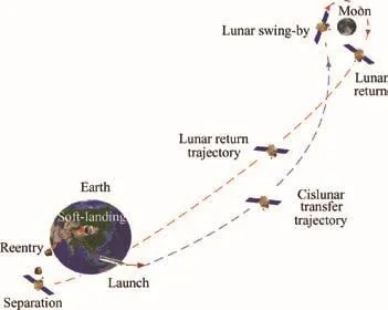
Fig.1 CHANG’E-5T1 mission of China.

Table 1 Orbit of service module at end of the CHANG’E-5T1 mission.
Firstly,the neighboring planets,Mars and Venus,are both over 40 million kilometers from the Earth.However,the antenna of the service module has only an effective distance of less than 30 million kilometers,making it infeasible to conduct planet exploration.Secondly,using the remaining propellant,the service module can escape from the Earth’s vicinity to become a man-made asteroid near the ecliptic.Although it is possible to approach asteroids and comets near the ecliptic,the antenna capacity will be a constraining factor,leaving only the Sun-Earth and Earth-Moon space as well as the corresponding LPs as feasible flight objectives.
Therefore,the SELPs and EMLPs,as well as the Moon,are considered as flight goals for the CHANG’E-5T1 extended mission.The decision can be further justified.Firstly,the EMLPs are valuable for future lunar exploration as they can provide vital support for navigation and communication relays for spacecraft in the cislunar space,especially behind the Moon,and serve as transfer terminals for future automatic sample return and deep-space exploration missions.13,14However,orbits near the EMLPs have a weak stability and a considerable degree of control difficulty.Thus far,the American Artemis mission is the only one that has performed a flight near the collinear EMLPs.21,22Moreover,no missions have been conducted regarding the triangular EMLPs.This means that some key flight technologies need to be tested for future applications at the EMLPs if the points are included in the extended mission.Secondly,in the Sun-Earth system,the L2 point was involved in the CHANG’E-2 extended mission,but the L1 point is an ideal position for researches on the geomagnetic field and solar and cosmic rays.Accordingly,the extended mission will be beneficial to the relevant mission if the L1 point can be included.Finally,the third phase of China’s lunar exploration will include automatically collecting a lunar sample and return the sample to the Earth,challenging the use of certain technologies new to Chinese space engineers such as lunar ascension,rendezvous,and docking.To conclude,testing the new technologies needed and directing the service module to the Moon will be essential to the third phase of China’s lunar exploration.
This paper will then investigate three different schemes and trajectories for the CHANG’E-5T1 extended mission with different flight goals,including the EMLPs,SELPs,lunar return,and a mixed one.
3.Design and control of transfer trajectories
With lunar return and the LPs in the Sun-Earth and Earth-Moon systems as flight goals,trajectories and the corresponding maneuver calculations will be the focus of the extended mission design.When lunar return is the only goal,trajectory design and maneuver calculation can be accomplished following the classic trajectory interception23and the differential correction method.When the LPs are included,the trajectory should be designed to reach an LP,or depart from one LP to another or to the Moon.The relevant mathematical models and methods of design and control are presented as follows for the transfer trajectories in the schemes.
Based on the analysis in Section 1,a direct LP orbit transfer and injection method is suggested to replace the current invariant manifold trajectory design method.In the circular restricted three-body problem,the general solution of a motion in the vicinity of a collinear libration can be expressed as

whereA1,A2,Ax,andAzare arbitrary constants,andc,¯k,ω,λ,and υ are constants described in Ref.18. φ and ψ are the phase angles of linear motion in thexyplane andzaxis,respectively.
As shown in Eq.(1),the basic condition for a spacecraft to orbit an LP naturally is that thex-axis-oriented velocity must be 0 when the spacecraft crosses thexzplane of the synodic coordinate system.Thex-axis-oriented velocity must be approximately 0 in a real dynamics environment.Utilizing this characteristic,the direct LP transfer and injection method needs to control the spacecraft to reach the vicinity of the LP,followed by correcting the initial state to force thexaxis-oriented velocity of the terminal state to be approximately 0 in the synodic coordinate system.Therefore,there are two steps,i.e.,the first is to approach the LP and the second to revolve around it.In the first step,the LP position is selected as the target of trajectory design,which has been widely studied in the field of trajectory design.
In the second step,the motion characteristic in Eq.(1)is utilized.The ideal target point for a controlled trajectory has a position and velocity state xd.Normally,the actual state before correction is not xdwhen integrated from the initial state x0after a flight timet;thus,x0andtmust be modified to ensure that the real state is equal to xd.The corrections for x0andtare denoted δx0and δt:

where Φ(t,t0)is the state transfer matrix of the trajectory from the initial epocht0tot.
For the CHANG’E-5T1 extended mission,when the initial state x0and epocht0are determinative,only the initial velocity v0and the flight timetcan be changed to ensure that thex-axis-oriented velocityvxdis equal to 0 when the trajectory crosses thexzplane.Eq.(2)becomes

where φ44,φ45,and φ46are the components of the fourth row and the fourth,fifth,and sixth columns of Φ(t1,t0),respectively,andaxdis thex-axis-oriented acceleration att.
The least-squares solution of the corrections of v0andt,i.e.,δv0and δt,can be calculated from Eq.(3)and by using the differential correction method.The general iteration proce-dure19,20is shown in Fig.2,in which Trial(1)indicates the trajectory of the first iteration,and Trial(2),Trial(n-1),and Trial(n)have similar meanings.Initial trajectory in Fig.2 is the design result of the first step which approaches the LP to a certain extent.Therefore,the actual initial trajectory must be corrected to approach the LP in the first step if it was apart from the LP too much.The second step produces Trial(1),Trial(2),Trial(n-1),and Trial(n)with the numeric iteration.When the iteration is convergent,the spacecraft can naturally perform a half or at the very least,a quarter of an orbit about the LP.In some cases,a small maneuver near the LP may be necessary for the spacecraft to enter a halo orbit or a Lissajous orbit.
Additionally,even though thex-axis-oriented velocity is selected as the target of correction,the sequent LP orbit is commonly a Lissajous orbit,and in some cases appears to be a quasiperiodic orbit when there is a large amplitude.Certainly,the correction target can involve thez-axis-oriented velocity to force the spacecraft to be injected into a halo orbit.
This method of direct LP orbit transfer and injection can avoid deriving an LP orbit with a broad field of design parameters and designing a transfer trajectory requiring a large manifold calculation.Instead,a transfertrajectory with a reasonable flight time and a corresponding LP orbit can be simultaneously obtained.Meanwhile,the control energy can be minimized with the transfer flight time designated as the design constraint.
After the spacecraft enters the LP orbit,it is convenient for it to depart from the orbit and return to the Moon following the invariant manifold.Theoretically,the spacecraft may only require a de-orbiting maneuver to depart from the LP orbit and reach the lunar vicinity by following a manifold.However,as the flight course is excessively long,a de-orbiting maneuver alone is often insufficient to bring the spacecraft into the lunar vicinity in such a way as to satisfy the terminal lunar condition,making the differential correction method ineffective in a real dynamic environment.To address this issue,Canalias used a multiple shooting method to separate the entire trajectory into multiple courses and then refine the trajectory to one in which the JPL ephemeris was considered.17Here presents a different method.As a mid-course correction maneuver is inevitable in a real mission,a return-trajectory control strategy is implemented to keep the number of maneuvers invariant by postponing the small de-orbiting maneuver and combining it with the mid-course correction maneuver into a single maneuver.This control strategy keeps the number of maneuvers the same for a long-course manifold trajectory in an actual dynamic environment,although it may require slightly more control energy.

Fig.2 Direct LP orbit transfer and injection.
4.Scheme for extended mission
Table 1 provides the parameters of the service module orbit for the design of the extended mission.In addition,some dynamics parameters are presented for the design.The mass of the service module is 1965 kg including the remaining propellant.The perturbation factors in the trajectory calculation include the solar radiation pressure and gravities of the Sun,Earth,Moon,and other planets.The positions of the celestial bodies are derived from the ephemeris of JPL DE421.The coefficient of solar radiation pressure has a value of 1.24.The gravity models for the Earth and Moon are JGM3 and LP165,respectively.The trajectory near the Earth accounts for the atmospheric drag with a coefficient of 2.2,and the cross-sectional area of the service module is 21.7 m.2
4.1.Scheme I
The flight goals set in Scheme I are SEL1,EML2,EML1,and return to the Moon.The service module enters a circular lunar orbit with an altitude of 200 km and an inclination of 45°,aimed at testing certain key rendezvous and docking technologies required in the third phase of Chinese lunar exploration.20
4.1.1.Flight to SEL1
SEL1 is the first flight goal of Scheme I.The direct LP orbit transfer and injection method described in Section 3 is adopted in designing the transfer trajectory to the point.The maneuver should be executed as early as possible to reduce control energy.Considering the time required by a precise orbit determination,the first maneuver is scheduled to occur 10–15 h after the separation.The control goal is to directly guide the service module into a halo orbit near SEL1.The resulting halo orbit has meanx-,y-,andz-oriented amplitudes of approximately 300000,930000 and 240000 km,respectively,in the Sun-Earth synodic coordinate system.Fig.3 shows the flight path of the service module in thexyplane of the synodic coordinate with the CHANG’E-5T1 mission trajectory.In Fig.3,Ctr1 is the first maneuver point.
4.1.2.Flight to EMLPs
After the flight to SEL1 is completed,the service module is guided to EML2.The trajectory design result is shown in Fig.4.The service module orbits SEL1 for approximately one revolution and then executes a trajectory maneuver(i.e.,Ctr2 in Fig.4(a))to depart from the L1 halo orbit and then fly to EML2.A mid-course correction maneuver,i.e.,TCM in Fig.4(a),is performed on day 131 after Ctr2.Based on the orbit design method,the service module can directly enter a Lissajous orbit near EML2 in the vicinity of Inj2(Fig.4(b)).The Lissajous orbit has meanx-,y-,andz-oriented amplitudes of approximately 14000,30000 and 42000 km,respectively,in the Earth-Moon synodic coordinate system.During the Earth-Moon libration orbit,orbital maintenance can be executed at an interval of half to one month depending on the trajectory tracking capacity.The service module orbits EML2 for approximately one month(Fig.4(b)).

Fig.3 Halo orbit near SEL1 and corresponding transfer trajectory of Scheme I.
The transfer trajectory requires a velocity increment of 141.5 m/s from SEL1 to the EML2 point.The trajectory requires a higher velocity increment than the natural transfer trajectory in Ref.17;however,the reference clearly indicates that it is difficult tofind the natural transfer trajectory for a Sun-Earth Lissajous orbit with az-oriented amplitude larger than 150000 km.The research results in the reference are consistent with the transfer case that has a Sun-Earth Lissajous orbit with az-oriented amplitude of 240000 km.
To test the TT&C technology for missions of EMLPs,a transfer trajectory from EML2 to EML1 is designed.With only one trajectory maneuver(i.e.,Ctr3 in Fig.4(b)),the service module departs from the L2 Lissajous orbit,thenflies to the L1 point,and naturally enters an L1 Lissajous orbit in the vicinity of Inj1 without any maneuvering(Fig.4(b))as indicated in the design;the module can orbit L1 for 2 revolutions with meanx-,y-,andz-oriented amplitudes of approximately 12000,31000 and 44000 km,respectively,in the Earth-Moon synodic coordinate system.
4.1.3.Return to the Moon
After orbiting EML1 for approximately 2.5 revolutions,the service module is directed to depart from the L1 Lissajous orbit and then return to the Moon.The trajectory follows the unstable manifold of the LP orbit.According to the results,the maneuver is executed at Ctr4(Fig.5)to bring the module back to the Moon in 16 days.In addition,a lunar brake is performed to send the module into the circular inclined lunar orbit.The trajectory of the course is shown in Fig.5.
In summary,the flight events and control parameters of Scheme I are listed in Table 2.
4.2.Scheme II
Scheme II is derived from Scheme I by modifying part of the flight course in Scheme I,i.e.,directing the service module to fly to the triangular EMLP after completing the EML1 flight rather than return to the Moon.Therefore,the flight goals of Scheme II are in the order of SEL1,EML2,EML1,SEL2,and triangle EMLP.
Scheme II involves a flight course from the collinear EMLP to the triangle EMLP,which has thus far received fewer attentions.An innovative concept of using SELPs is proposed in this paper to achieve a transfer from the collinear EMLP to the triangular EMLP.The service module is controlled to depart from EML1 to SEL2,and then deviate from SEL2 to the triangular EMLP before finally entering an orbit circling the triangular point with a maneuver.The transfer trajectory design is the same as that for Scheme I.
Fig.6 is the trajectory of Scheme II,in which the flight course from the separation to EML1 is omitted as it repeats the steps in Scheme I.The departure maneuver from EML1 is executed at Ctr4 in Fig.6(a),which causes the service module to fly from the L1 point to SEL2 via the Moon and EML2 in turn.Based on the design,the module should naturally enter a halo orbit near SEL2 without a maneuver.To return to the Earth-Moon space,the module will execute a trajectory maneuver in the vicinity of SEL2(i.e.,TCM in Fig.6(b))and then another maneuver 82 days after TCM(i.e.,Ctr5 in Fig.6(b))to fly to the vicinity of EML4 in Fig.6(b).The coordinate systems are the Earth-Moon synodic system(Fig.6(a))and the Sun-Earth synodic system(Fig.6(b)).The positions of the Moon at the beginning and end of the flight course are shown in Fig.6(b).
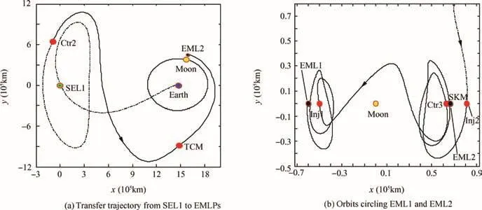
Fig.4 Trajectory of Scheme I.

Fig.5 Trajectory of returning to the Moon from EML1 in Scheme I.
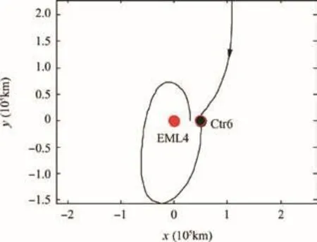
Fig.7 Transfer trajectory and orbit near EML4 in Scheme II.
In the vicinity of EML4,a maneuver is performed at Ctr6(Fig.7)to enable the module to enter the orbit near EML4.Due to the dynamic stability of the triangle EMLP,the service module should circle EML4 for several months(or even longer)without any TT&C support.
A summary of the flight events and control parameters of Scheme II is provided in Table 3.
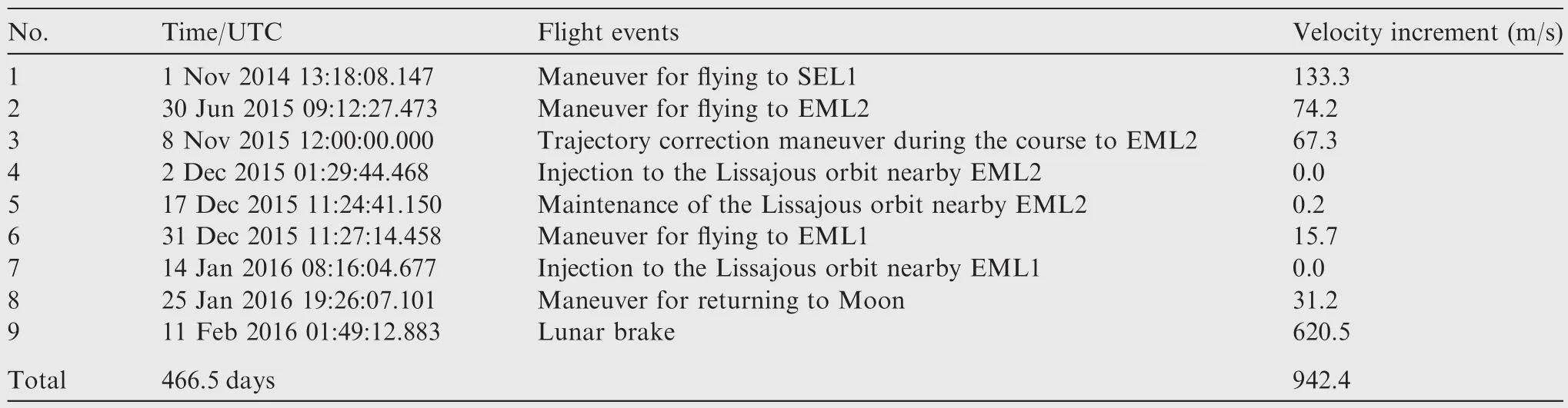
Table 2 Flight events and control parameters of Scheme I.

Fig.6 Scenario of Scheme II.

Table 3 Flight events and control parameters of Scheme II.
4.3.Scheme III
The flight goals of Scheme III are EML2 and lunar return.In Scheme III,the service module firstly encounters the Moon after the separation,and then enters the L2 Lissajous orbit via lunar swing-by before finally returning to the Moon and performing an injection into the circular inclined lunar orbit.
The procedure for Scheme III can be divided into two stages:the first stage is from the separation to the entry into the Earth-Moon L2 Lissajous orbit,and the second stage from L2 to the Moon.24The transfer trajectory in the first stage must firstly encounter the Moon and then be corrected to fly by the Moon to enter the L2 orbit.This type of transfer trajectory is superior to other types:it can save 120–800 m/s of velocity increment compared with direct transfer trajectories to the LP25,26and save 70–100 days of flight time compared with weak stability transfer trajectories.27,28The second phase,the trajectory from L2 to the Moon,is similar to the one in Section 4.1.3.
Fig.8 shows the trajectory of Scheme III,with Fig.8(a)being the first stage.Trajectory a in Fig.8(a)requires three maneuvers to encounter the Moon,with distinctly different semi-major axes in two Earth-centric ellipses.In fact,the three maneuvers can be reduced to one(i.e.,the second maneuver in Scheme A)to encounter the Moon if a decrease of the apogee altitude is achieved by the avoidance maneuver.As a result,the transfer trajectory(i.e.,Trajectory b in Fig.8(a))has identical ellipses.The Earth-Moon L2 orbits and lunar-return trajectories for Trajectories a and b are shown in Fig.8(b)and(c),respectively,in which Ctr and TCM are the perilune and lunarreturn maneuvers,respectively.
A summary of the flight events and control parameters of Scheme III is shown in Table 4,indicating that Trajectory b has approximately the same flight time as that of Trajectory a,but with fewer maneuvers and a smaller velocity increment.
4.4.Comparison
The flight itineraries of the three schemes are shown in Fig.9.Clearly,Schemes I and II have longer flight itineraries and more flight goals than those of Scheme III,suggesting that Schemes I and II have greater mission values but longer flight time,resulting in increased mission operation and fuel costs.
The scheme parameters of the CHANG’E-5T1 extended mission are compared and listed in Table 5.
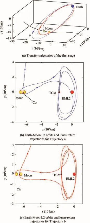
Fig.8 Trajectories of Scheme III.

Table 4 Flight events and control parameters of Scheme III.
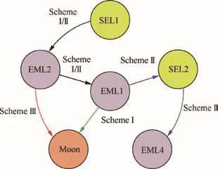
Fig.9 Flight itineraries of the designed schemes.
It shows that the three schemes all require a velocity increment less than that provided by the remaining propellant,and each scheme has its own characteristics.Schemes I and II require less control energy and have more flight objectives than those of Scheme III.More specifically,Schemes I and II can achieve flight goals of the collinear EMLPs and the triangle EMLP which has never been explored before;nevertheless,the two schemes require longer flight time,more maneuvers,and longer flight distances than those of Scheme III.Due to these negative factors,the mission period and cost as well as potentialrisks willconsiderably increase.In contrast,Scheme III,designed to complete a flight to EML2 which has thus far been accomplished only by the Artemis Mission,is characterized by reduced flight time and control energy.
Therefore,with the approval of the Chinese lunar exploration and space project center,Scheme III was applied as the flight scheme for the CHANG’E-5T1 extended mission.The actual flight course took Trajectoryain Scheme III with negligible operation errors.As a result,the CHANG’E-5T1 extended mission was successfully implemented in late 2014,proving the mission plan effective and efficient.Furthermore,there were some additional flight tests after the spacecraft returned to the Moon,which will be the focuses of future publications.
5.Conclusions
This paper describes the design of the CHANG’E-5T1 extended mission,which makes full use of the remaining propellant of the CHANG’E-5T1 mission,and introduces three schemes and their respective trajectories.To solve the issue of transfer trajectory design,the direct libration point orbit transfer and injection method was presented to reduce work of calculation required by the current manifold method.An innovative concept has been developed over transfer from the Earth-Moon collinear libration point to the triangle point via the Sun-Earth/Moon libration point.Design results show that the remaining propellant is sufficient to support an extended mission involving many innovative and valuable flight tests and pioneering flight goals,including the first flight to the triangular Earth-Moon libration point and several Sun-Earth and Earth-Moon libration points.Scheme III,a flight to the Earth-Moon L2 point and return to the Moon,was chosen to test the key technologies of the third phase of Chinese lunar exploration,resulting in reduced flight time and control energy while achieving the expected goals.The success of the CHANG’E-5T1 extended mission in late 2014 represents the second flight to the Earth-Moon libration point after the Artemis mission.The research findings are significant to the CHANG’E-5T1 extended mission and expected tofind applications in future lunar,libration point,or other deep-space missions,particularly missions involving multiple libration points and lunar farside exploration such as CHANG’E-4.
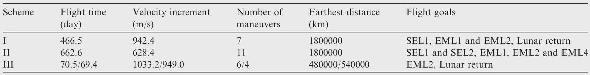
Table 5 Scheme comparison.
Acknowledgements
The authors are grateful for the supports of this study by the NationalNaturalScienceFoundation ofChina (Nos.11773004,61573049,11303001,61571032)and the Major Special Project of the National Lunar Exploration of China.The authors would like to thank all teammates of the CHANG’E-5T1 flight control team for their contributions to and supports of this work.The authors would also like to especially acknowledge the contributions of Prof.LIU Yong,Dr.CAO Jianfeng,Prof.XIE Jianfeng,Prof.WU Weiren,and Prof.ZHOU Jianliang for helping improve this manuscript to its final form.The authors also express gratitude to the reviewers for their feedback.
杂志排行
CHINESE JOURNAL OF AERONAUTICS的其它文章
- Particle image velocimetry for combustion measurements:Applications and developments
- Abnormal changes of dynamic derivatives at low reduced frequencies
- A new hybrid aerodynamic optimization framework based on differential evolution and invasive weed optimization
- Experimental study of an anti-icing method over an airfoil based on pulsed dielectric barrier discharge plasma
- Envelope protection for aircraft encountering upset condition based on dynamic envelope enlargement
- Effects of the radial blade loading distribution and B parameter on the type of flow instability in a low-speed axial compressor