Experimental study of an anti-icing method over an airfoil based on pulsed dielectric barrier discharge plasma
2018-07-24YongqiangTIANZhengkeZHANGJinshengCAILeileiYANGLeiKANG
Yongqiang TIAN,Zhengke ZHANG,Jinsheng CAI,Leilei YANG,Lei KANG
National Key Laboratory of Science and Technology on Aerodynamical Design and Research,Northwestern Polytechnical University,Xi’an 710072,China
KEYWORDS Anti-icing;Icing wind tunnel;Lissajous figures;Plasma actuator;Pulsed dielectric barrier discharge
Abstract Aircraft icing has long been a plague to aviation for its serious threat to flight safety.Even though lots of methods for anti-icing have been in use or studied for quite a long time,new methods are still in great demand for both civil and military aircraft.The current study in this paper uses widely used Dielectric Barrier Discharge(DBD)plasma actuation to anti-ice on a NACA0012 airfoil model with a chord length of 53.5 cm in a closed-circuit icing wind tunnel.An actuator was installed at the leading edge of the airfoil model,and actuated by a pulsed low-temperature plasma power source.The actuator has two types of layout,a striped electrode layout and a meshy electrode layout.The ice accretion process or anti-icing process was recorded by a CCD camera and an infrared camera.Instantaneous pictures and infrared contours show that both types of DBD plasma actuators have the ability for anti-ice under a freestream velocity of 90 m/s,a static temperature of-7°C,an Median Volume droplet Diameter(MVD)of 20 μm,and an Liquid Water Content(LWC)of 0.5 g/m3.The detected variations of temperatures with time at specific locations reveal that the temperatures oscillate for some time after spraying at first,and then tend to be nearly constant values.This shows that the key point of the anti-icing mechanism with DBD plasma actuation is to achieve a thermal equilibrium on the model surface.Besides,the power consumption in the anti-icing process was estimated in this paper by Lissajous figures measured by an oscilloscope,and it is lower than those of existing anti-icing methods.The experimental results presented in this paper indicate that the DBD plasma anti-icing method is a promising technique in the future.
1.Introduction
Aircraft icing can occur both on ground and in flight under icing conditions.Typical ground icing types are slush,clear ice,and a combination of the two,which are usually caused by snow or freezing rain falling on the aircraft surface.In- flight icing is caused by supercooled water droplets in clouds which are usually in a metastable condition.When an aircraft encounters supercooled water droplets in flight,the droplets may either change their phase to form ice crystals the moment they impact the surface,or collect into a thin water film and flow downstream along the aircraft surface by the resultant force of aerodynamic,gravity,and surface adhesion forces.The typical atmospheric temperature associated with aircraft icing ranges from-40 °C to 0 °C.1
Ice accretion on aircraft surface is usually classified as clear(or glaze)ice,rime ice,mixed ice,and hoar frost.2Clear ice always occurs at temperatures ranging from-18 °C to 0 °C,and the size of supercooled water droplets leading to clear ice is relatively large.In clear-ice situations,when supercooled droplets impact aircraft surface,the freezing process is relatively gradual due to the latent heat released in the freezing process,allowing some of the water droplets to flow rearwards before they solidify.Thus a sheet of solid,clear,glazed ice is formed with very little air enclosed,and has a density of 0.917 kg/m3close to that of water.2,3Rime ice occurs at lower temperatures(-40 °C to-10 °C),and the size of supercooled water droplets to be frozen to rime ice is relatively tiny.Because of the smaller volume of supercooled water droplets,the freezing process is so fast that they solidify upon impacting.In the process of rime ice formation,air is entrapped between frozen droplets,that’s why rime ice is with a white appearance.Therefore,rime ice is a mixture of tiny ice particles and trapped air with a density of 0.88 kg/m3.2,3Actually,different moistures and droplet sizes commonly exist in clouds,and this variation can produce a mixture of clear ice(from larger drops)and rime ice(from smaller droplets),known as mixed ice,which is the most common ice encountered in flight.Hoar frost occurs when moist air comes in contact with aircraft surface at sub-zero temperatures,where water vapor changes directly to ice and deposits in the form of frost without condensing to liquid water,and thus it is a white crystalline coating which can be brushed off.2,3
The locations where icing occurs most frequently on aircraft are always the leading edges of wings and empennages,the propellers,hubs,engine nacelles,rotor blades,windshields and some sensors.4Ice accretion on wings and rotor blades can increase drag and decrease lift,and moreover,change the moment characteristics.5–7Propellers’thrust efficiency will decrease once ice forms on them.Ice accretion on engine nacelles and hubs will reduce the efficiency of the engine,once the dislodged ice crystals are ingested,the engine is very possibly to be destroyed.8–10Windshields icing will influence the view of pilots and sensors icing can mislead pilots.11,12Generally speaking,Aircraft icing is a dangerous phenomenon which threatens flight safety.
To ensure flight safety,anti-icing and deicing methods are indispensable for aircraft.Anti-icing refers to prevention of any ice formation during flight.Deicing refers to the case when ice has already formed on aircraft surface,and then is removed with some methods.1Methods for anti-icing and deicing under investigation or in use are mainly classified into four kinds:(A)freezing point depressant method;(B)thermal method;(C)mechanical method;(D)surface modification method.The freezing point depressant method usually uses anti-icing/deicingfluids such as ethylene glycol and propylene glycol to lower the freezing point of supercooled water droplets and melt existing ice accretion.The shortcomings of this method lie in its low efficiency at extreme conditions and its pollution to the environment.13–16The thermal method is to deliver heat flux to the aircraft surface,forming a hot boundary layer on the surface to prevent the phase transition of supercooled water droplets into ice or to melt solidified ice crystals.This kind of method involves using hot compressor gases,hot exhaust gases,hot oil,or electrical energy.Even though this method has features of simplicity and fast response,the energy consumption is very high.1,16,17The mechanical method is to deform the aircraft surface to break the structure of ice accretion,smash the ice,and remove the ice dregs from the surface by air flow and gravity force.This kind of method includes pneumatic boots,Electromagnetic Impulse DeIcing(EIDI),and electromagnetic expulsive boots.It can only deice,and additional drag is unavoidable1,18,19The surface modification method is to modify the physical and chemical properties of the surface to change the contact state of water and the surface,such as contact angle and roll-off angle,to reduce ice adhesion and accumulation on the surface.The most popular method of this kind is hydrophobic and superhydrophobic coatings.20However,the serviceability of coatings in humid environments has been doubted,and much more research is needed before real applications.16,21–23
Although lots of anti-icing and de-icing methods have been in use or studied for quite a long time,new methods are still in great demand in both civil and military aircraft communities.Dielectric Barrier Discharge(DBD)plasma actuation has been widely studied and applied in flow control such as flow separation suppression,lift augmentation,and drag reduction for more than a decade,exhibiting potential applications to active flow control over various aircraft.24,25Fig.1 shows a single DBD plasma actuator which consists of an exposed electrode and a covered electrode with a layer of dielectric placed in between to insulate them.The actuator is driven by an Alternating Current(AC)voltage source which could be sinusoidal,squared,triangle,pulsed,etc.in a voltage wave form.The collision of ions in the plasma resulting from discharge transfers momentum to the boundary layer,inducing an air flow accelerating and moving away from the exposed electrode as shown in Fig.1.This accelerating effect can be regarded to be equivalent to an imaginary volumetric force acting on thefluid.Besides,DBD plasma actuators have obvious thermal effects,and can heat the dielectrics below the exposed electrodes and the ambient air.The thermal characteristics of DBD plasma have been studied by researchers,which indicated that the rotational temperature of the weakly ionized plasma can reach as high as 200 °C.26–29
This paper applied DBD plasma actuation to anti-icing on an airfoil in an icing wind tunnel to verify its effectiveness,and explored its mechanism of anti-icing.The experimental process was recorded by a CCD camera,and the surface temperature variation was captured by an infrared camera.The mechanism of DBD plasma anti-icing was investigated based on the temperature information.Finally,the power consumption of DBD anti-icing was estimated and compared with the results of some existing methods.
2.Experimental setup,instrumentation,and model
Anti-icing experiments on an airfoil were conducted in the FL-61 icing wind tunnel located at the Aerodynamic Institute of Aviation Industry Corporation of China(AVIC).The tunnel is a closed-circuit continuous wind tunnel with a test sectional size of 0.6 m(width)×0.6 m(height).It can provide supercooled droplets of a Median Volume droplet Diameter(MVD)ranging from 15 μm to 50 μm by spraying atomized water into the tunnel circuit in the settling chamber.The wind tunnel flow has a Liquid Water Content(LWC)of 0.2 g/m3to 3.0 g/m3and a static temperature between -40°C and room temperature.Besides,the static pressure can vary from 39 kPa to 100 kPa,which can simulate a corresponding altitude from sea level to 7000 m.A schematic diagram of the icing wind tunnel is shown is Fig.2.
The model used in the experiments is an NACA0012 airfoil with a span of 600 mm and a chord length of 535 mm,which is made of Acrylonitrile-Butadiene-Styrene(ABS)for its good insulating and mechanical properties.
A CTP-200 K pulsed low-temperature plasma power source was adopted in the experiments;its input voltage is 220 V and its output voltage can reach as high as 30 kV.The waveform of the output voltage is periodic with a period of microsecond order of magnitude and a frequency of 7–15 kHz.The maximum output power is 1 kW.The power source has one highvoltage output monitor and two current output monitors.To detect the current,one current output monitor can output an instantaneous current on a 50 Ω sampling resistor,while the other can output a Lissajous figure via a 0.47 μF sampling capacitor.

Fig.2 Schematic of FL-61 icing wind tunnel.
Theexperimentalsystem isshown in Fig.3.The NACA0012 airfoil was installed in the test section with a fixed angle of attack of 4°.Two kinds of plasma actuators were mounted around the leading edge of the model.The covered electrodes of the two actuators are rectangular copper foils of 35 μm thickness,153 mm length,and 87 mm width,respectively.The dielectric used in the actuators is ABS shells of 1 mm thickness,and is curved to conform to the shape of the model’s leading edge to minimize its influence on the model geometry.The only difference between the two kinds of actuators lies in that they have different geometric arrangements for their exposed electrodes.One geometric structure for the exposed electrode is a parallel layout in which 10 long straight striped copper electrodes are placed parallel to each other in the streamwise direction and connected parallel in an electrical sense(hereinafter referred to as ‘striped electrode”),where each striped electrode has a thickness of 35 μm,a width of 0.6 mm and a length of 133 mm,respectively,and the distance between each two adjacent electrodes is 6 mm(see Fig.4).The other geometric structure,called ‘meshy electrode”,for the exposed electrode,which also has a thickness of 35 μm,is a squared-grid layout,where each squared cell has a size of 10 mm×10 mm,and each side of the cell has a width of 1 mm(see Fig.4).The electrodes mounted around the leading edge surface are actuated by the plasma power source.The striped electrode is a typical arrangement used influid flow control with the electrode lengthwise direction perpendicular to the free stream direction,whereas in the current experiments,the electrode lengthwise direction is in the streamwise direction.The meshy electrode increases the length of discharge edges in its lengthwise direction compared with the striped electrode in the same model surface area to make some difference in the arrangement.The voltage signals on the actuators were measured and stored by an oscilloscope.
The anti-icing process was recorded by a CCD camera which was mounted on the test section’s side-wall observation window,while the model surface temperature was measured and recorded by an infrared camera which was fixed on the test section’s top-wall observation window.
3.Experimental results
Experiments were conducted under the condition of a freestream velocity of 90 m/s,a static temperature of-7°C,an MVD of 20 μm,and an LWC of 0.5 g/m3.The peak-peak value of the pulsed voltage discharged from the exposed electrode was 17.79 kV with a frequency of 11.67 kHz in the striped-electrode case and 19.12 kV with a frequency of 11.04 kHz in the meshy-electrode case.The waveforms of discharged voltagesUare shown in Fig.5,tis the time.
When the test section flow was controlled to specified freestream conditions,the plasma power source was turned on,and its parameters were adjusted to make the voltage of the actuator reach a preset value to discharge,and then the spraying system started at the same time when the anti-icing process started.
Fig.6 shows the anti-icing process of the striped electrode.In Fig.6,before the spraying system started,the discharge glow from the striped electrode was bright and uniformly distributed on both sides of each electrode.However,at the moment supercooled water droplets impacted on the leading edge just immediately after the spraying system started,the discharge glow at the leading edge disappeared as soon as the electrode was covered by a thin water film.Soon afterwards,the discharge glow reappeared gradually but with a lower brightness than before,and some areas were even fully dark without glow.At 30 s after the spraying started,the glow distribution became stable and began to remain unchanged.No ice accretion occurred on the area covered by the electrode,but other parts of the leading edge were covered by some ice crystals.As time went on,no ice accretion occurred on the area covered by the electrode,but the ice accretion on other areas of the leading edge grew thicker and thicker.
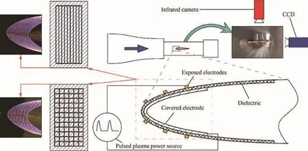
Fig.3 Schematic illustration of experimental system.
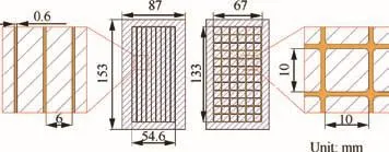
Fig.4 Geometric structures of two exposed electrodes.

Fig.5 Waveforms of discharged voltages from striped electrode and meshy electrode in anti-icing tests.
Fig.7 shows pictures of the upper and lower surfaces around the leading edge of the airfoil after the spraying system was stopped,which may reflex the anti-icing effects of the striped electrode to some extent.The area cover by the striped electrode was as clean as it was before spraying,while other areas of the leading edge along the spanwise direction were covered by ice accretion.The above process shows that the DBD plasma generated by the striped electrode can prevent ice accretion on the leading edge.
Fig.8 shows the evolution of infrared temperature contours with time in the anti-icing process of the striped electrode.It can be seen that before spraying,the temperature in the area covered by the electrode was much higher than the freestream static temperature,and on the airfoil surface,the closer to the electrode,the higher the temperature.However,at the moment when the spraying system was started and supercooled water droplets impacted on the leading edge,the temperature in the area covered by the thin water film went down a little,while the temperature in other areas remained nearly the same as that before spraying.At 30 s after the spraying started,the temperature distribution became stable and began to remain unchanged.Still,the closer to the electrode,the higher the temperature.The only difference is that the peak temperature was decreased by about 8°C.Nevertheless,the temperature in the electrode area was still much higher than the freestream value.
Fig.9 shows the anti-icing process of the meshy electrode.Under the given actuating voltage and frequency as mentioned above,similar situations in some aspects occurred here,i.e.,after the spraying system started,a very thin water film formed on the model surface,while the discharge glow over some areas of the electrode was visible,but invisible over other areas of the electrode.The areas where the glow was invisible should be the place where no gas discharge happened.The discharge glow became stable at 30th second after the start of spraying,and remained unchanged afterwards.Ice accretion did not occur in the area covered by the electrode,while grew thicker and thicker on other parts of the leading edge.
Fig.10 shows pictures of the upper and lower surfaces around the leading edge of the airfoil after the spraying system was stopped,which illustrate the anti-icing effects of the meshy electrode to some extent.The area covered by the meshy electrode was as clean as it was before spraying,while other areas of the leading edge in the spanwise direction were covered by ice accretion.The above process shows that the DBD plasma generated by the meshy electrode can prevent ice accretion on the leading edge.
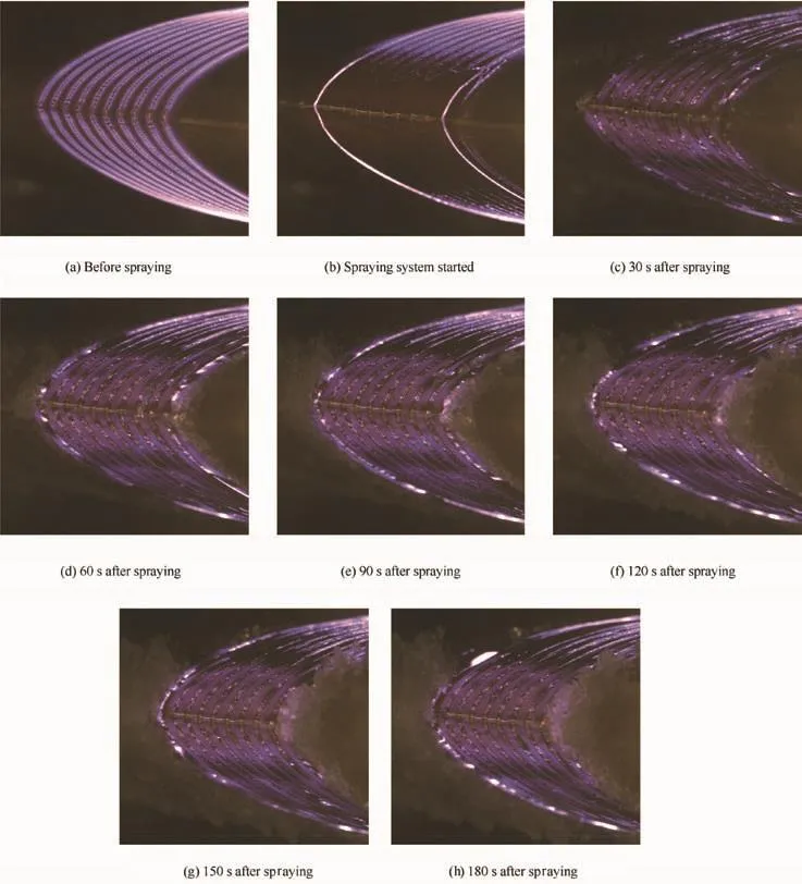
Fig.6 Anti-icing process of the striped electrode.

Fig.7 Upper and lower surfaces of leading edge after anti-icing process(the striped electrode case).
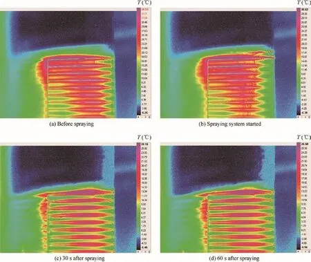
Fig.8 Evolution of infrared temperature contours with time in the anti-icing process.
4.Mechanisms of DBD plasma anti-icing
To investigate the DBD plasma anti-icing mechanisms,some specific surface points are selected as monitoring points to trace the variations of surface temperatures with time at these points.As is shown in Fig.11,pointsA,B,C,which are respectively the mid-points between electrodes 1 and 2,3 and 4,and 5 and 6,are located along a spanwise straight line(y-axis direction)on the upper surface near and downstream of the leading edge.Similarly,pointsD,E,F,which are respectively the mid-points between electrodes 1 and 2,3 and 4,and 5 and 6,are located along a spanwise straight line on the upper surface immediately downstream of the mid-chord point.PointsG,M,NandH,P,Q,which are on the side edges of electrodes 1,5,and 6,respectively,are located on the same lines as pointsA,B,Cand pointsD,E,F,respectively.
Fig.12(a)demonstrates the evolution histories of the surface temperatures at pointsA,B,C.The three temperatures kept a value about 12°C beforet=5.4 s.Att=5.4 s,when the spraying system started,the three temperatures went down sharply to about 5°C at 6.4 s within about 1 s,and then underwent a slight increase to about 6°C at about 7.4 s.After this instant,the surface temperatures went down slowly to reach about 5°C untilt=35 s,and then remained a constant value of 5°C thereafter.
Similar phenomena occurred for the evolution histories of the surface temperatures at pointsD,E,F,pointsM,N,and pointsP,Qas shown in Fig.12(b)–(d),respectively.That is to say,before supercooled water droplets impacted the surface,the temperatures kept a relatively high constant valueT0.At the moment of impacting(t=t0),the surface temperatures went down sharply to a relatively low value within a very short periodoftime(about1to2 s),andthenstartedtogouptoacertainvalue,followedbydecreasingtoordirectlykeepingataconstantvalueofT1att=t1.ThesefeaturesaresketchedinFig.13.
Temperature is a physical quantity which represents the degree of hotness or coldness of a body or a medium macroscopically,and is a measure of the average kinetic energy of the random motion of the molecules of afluid microscopically.That temperature remains constant means that a thermal equilibrium on a model surface is achieved.
The heat fluxes in the anti-icing process include the following30
(1)The specific heat flux convected away from the body surface caused by the difference between the body surface temperature and the boundary layer outer edge temperature(qa).
(2)The specific heat flux added to the body surface by the boundary layer friction(qv).
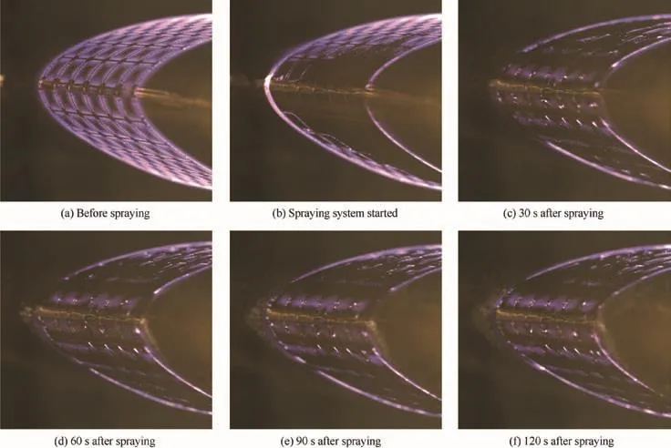
Fig.9 Anti-icing process of the meshy electrode.
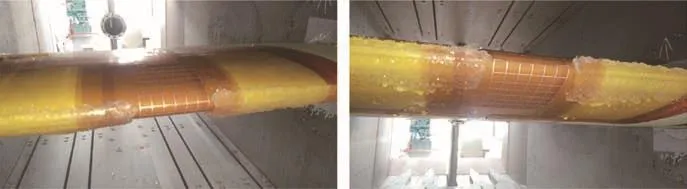
Fig.10 Upper and lower surfaces of the leading edge after the anti-icing process(the meshy electrode case).

Fig. 11 Locations of monitoring points for surface temperatures.
(3)The specific heat flux needed for the surface water to evaporate(or the specific heat flux needed for ice to sublime)(qe).
(4)The specific heat flux needed to heat the supercooled droplets collected by the body surface(qw).
(5)The specific heat flux converted from the kinetic energy of the water droplets due to their stagnations when collected by the body surface(qwv).
(6)The specific heat flux radiated from the body surface to the air(qr).
(7)The specific heat flux of fusion representing the amount latent heat required to convert unit mass of ice into water without a change in temperature or that released to the surroundings to make unit mass of water freeze(qt).
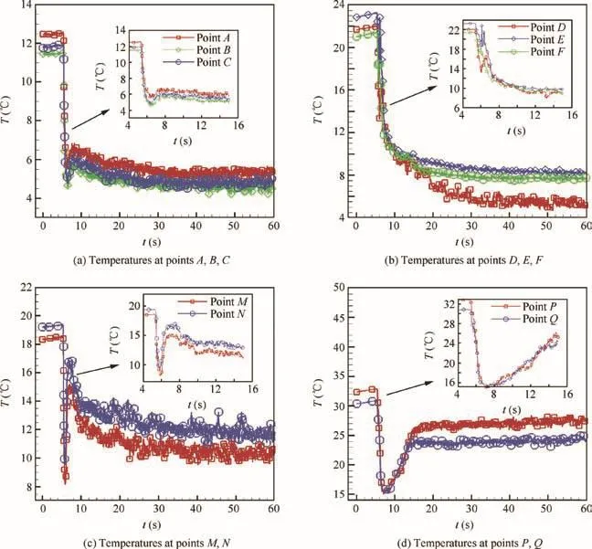
Fig.12 Variations of surface temperatures.
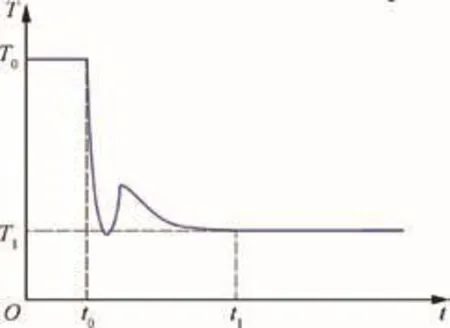
Fig.13 Evolution history of surface temperature.
(8)The specific heat flux released by plasma discharge to the surroundings(qd).
(9)In the anti-icing process,the surface is covered by a very thin film of water,and henceqrcan be neglected.Therefore,the thermal equilibrium equation of the surface can be written as

This indicates that the mechanism of the DBD plasma antiicing process is to maintain the thermal equilibrium of the wet surface by DBD plasma actuation.
As is shown in Figs.6 and 9,the brightness distribution of the discharge glow reached a relatively steady state,that is,some areas were covered by slight discharge glow while other areas were dark,and the brightness distribution hardly varied with time.It is certain that the place where the glow occurred is the place where strong gas discharge happened and the temperature was relatively high.As is mentioned above,DBD plasma inside a gas has significant thermal effects,which is part of the sources of heat flux for anti-icing.However,comparing the photos in Fig.6 with the infrared pictures in Fig.8 indicates that the dark areas have comparable temperature values to those in the bright areas.To see this more clearly,Fig.14 presents the surface temperature distributions along linesGNandHQafter the temperatures reached a steady state.The temperature distributions exhibit certain features of oscillation along the two lines,which indicated that the closer the position to the discharge edges,the higher the temperature,and that the peak temperature values occurred on the edges of each electrode,and the temperature value at the mid-point of the cross section of each electrode was the lowest.The lowest temperature points form a mid-line along each electrode.The temperature oscillations along linesGNandHQhave the same regularity except the difference in values.In contrast,the photos of the model surface in Fig.6 corresponding to the temperature distribution in Fig.14 show that the distribution of bright and dark areas is irregular in the spanwise direction.This reveals that some dark areas also had high temperatures and might have been heated.The source of heat is supposed to be associated with the status of discharge which depends on the thickness of the local water film in the vicinity of the discharge edge of the exposed electrode.
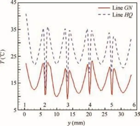
Fig.14 Surface temperature distributions along lines GN and HQ after they reach a steady state.
Usually the water film thickness is not uniformly distributed on the surface due to the difference in the resultant force of the aerodynamic,gravity,and surface adhesion forces at different locations.Thus the surface water film can be classified into two typical modes:one is that the water film thickness is smaller than the height of the exposed electrode as shown in Fig.15,and the other is that the water film thickness is greater than or equal to the height of the exposed electrode as shown in Fig.16.In the former case,part of the edge of the exposed electrode is in direct contact with the air,while the remaining part is immersed in the water film,and then gas discharge and liquid discharge occur simultaneously.If the water film is much thinner than the exposed electrode,strong gas discharge happens and dominates the heating process of the water film,increasing the temperature and emitting bright glow.Otherwise,weak gas discharge and liquid phase discharge jointly heat the water film,increasing the temperature,but without glow.In the latter case,the electrode edge is completely covered by the water film;then,no gas discharge can happen,and no glow appears,so the area near the electrode is dark.In this case,liquid phase discharge happens without gas discharge and heats the water film,increasing the temperature without glow.

Fig.15 Surface water film mode when its thickness is smaller than that of exposed electrode.

Fig.16 Surface water film mode when its thickness is greater than or equal to that of exposed electrode.
Therefore,high temperature near the vicinity of the discharge edge of the exposed electrode can happen in three situations:(A)strong gasdischarge emitting brightglow dominates heating in a very thin water film case;(B)weak gas discharge and liquid phase discharge jointly heat the water film without glow in a moderate water film thickness case;(C)only liquid phase discharge heats the water film without glow in a completely covered exposed electrode case.
5.Estimation of power consumption of DBD plasma in anti-icing
5.1.Lissajous figure and electric circuit model
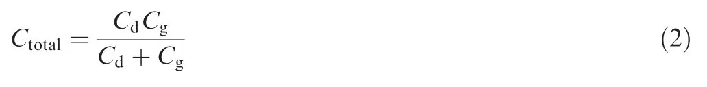
Usually,it is difficult to measure the power consumption of DBD plasma.One proper method is the Lissajous figure method.31An ideal form of the Lissajous figure for DBD plasma is shown in Fig.17.The capacitance of the DBD plasma actuator can be regarded as a serial connection of the dielectric capacitanceCdand the gas gap capacitanceCg,and then the total capacitanceCtotalcan be calculated by
CdandCtotalcan also be represented by the slopes of the two edges of the Lissajous figure,as are shown in Fig.17.
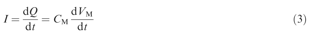
In the Lissajous figure method,a sampling capacitor(with a capacitance ofCM)is added in a series connection to the discharge circuit to measure the transported quantity of the electric chargeQ.The voltage over the sampling capacitor isVM,and the current in the circuit is
The power consumption can be calculated by


Fig.17 Ideal Lissajous figure of the DBD plasma actuator.
whereTpandfare the time period and frequency of the discharge,respectively,andVis the voltage on the actuator.In this experiment,Vin fact isVA,the voltage over the actuator.Since the icing wind tunnel used in this experiment is made of steel,when electric wires passed through the holes on the wall,a stray capacitance formed in a parallel connection to the discharge circuit.This caused the measured value of voltage over the sampling capacitor(CM)to be amplified to some times.A proper correction method was adopted to estimate the true power consumed in DBD plasma anti-icing.Assume that the stray capacitance caused by the induction between the high-voltage electric wires and the wind tunnel wall isCT,and thatVMiandVMrrepresent the voltages over the sampling capacitor in an ideal circuit(without a stray capacitance)and a real circuit(with a stray capacitance),respectively,in other words,VMiis the corrected voltage value ofVMr,and will be used to replaceVMin Eqs.(3)and(4).They can be calculated by the capacitive voltage divider principle as follows:
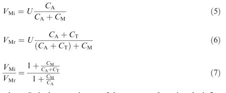
whereCAis the capacitance of the actuator.Ignoring the influence of the water film onCA,its value can be measured by a universal meter.The value ofCMis a known value.The only unknown isCTwhich is associated with the ratioVMr/VAand can be estimated by measured values.
The electric circuit of DBD plasma anti-icing wind tunnel experiments is shown in Fig.18.The electric power used was a sinusoidal alternating current with a voltage of 220 V,and the total power consumed in the electric circuit was measured by a digital electric power meter installed in the input end of the circuit.A sampling capacitor of 0.1 μF was inserted in the circuit.An oscilloscope was used to acquireVMrandVAfor the Lissajous figures in power consumption calculation.
5.2.Estimation of stray capacitor and power consumption
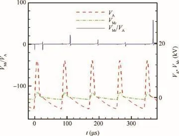
Fig.19 Variations of VMr,VA,and VMr/VAwith time in striped electrode case.

Fig.20 Variations of VMr,VA,and VMr/VAwith time in meshy electrode case.
Figs.19 and 20 present the variations ofVMr,VA,and the ratioVMr/VAin the anti-icing process in striped and meshy electrode cases,respectively.It can be seen that the ratio ofVMrtoVAis nearly constant except some discrete instants.
Let

and then according to the capacitive voltage divider principle
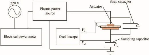
Fig.18 Electric circuit model of DBD anti-icing experiments.

the value ofCTcan be estimated as
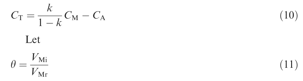
Substituting Eq.(10)into Eq.(7)leads to

Then,Eq.(4)can be rewritten as follows by replacingVMbyVMr:

whereCM=0.1 μF is already known,andCAcan be measured by a universal meter.The measurement value is:CA=0.06 nF and 0.08 nF,respectively for the striped and meshy electrodes.On the other hand,the constantkcan be estimated by the least squared method,and the results are 0.142 and 0.121,respectively for the two electrodes.The corresponding estimated values ofCTare 16.35 nF and 10.714 nF from Eq.(10),respectively.Finally,the values of θ are estimated to be 0.00425 and 0.0066,respectively,by Eq.(12).
Figs.21 and 22 give the measured Lissajous figures in one discharge period of DBD plasma actuation in the anti-icing process using striped and meshy electrodes,respectively.By calculating the integral in Eq.(13),the power consumption in the striped electrode in anti-icing is 53.43 W.By dividing the area of the surface region where the exposed electrode is paved,the power consumption per unit area is found to be 7.358 kW/m2.Similarly,the power consumption for the meshy electrode is 74.73 W,the power consumption per unit area is 8.386 kW/m2.
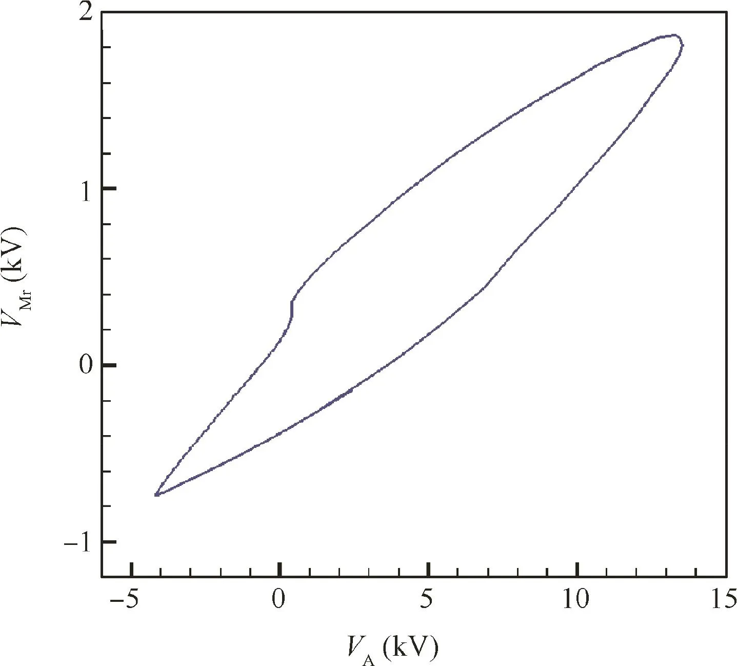
Fig.21 Lissajous figure of anti-icing in striped electrode case.

Fig.22 Lissajous figure of anti-icing in meshy electrode case.
The total power consumptions measured by the digital electric power meter in the whole system in striped and meshy electrode situations,are 222.7 W and 250 W,respectively.The corresponding total power consumptions per unit area are 30.667 kW/m2and 28.055 kW/m2,respectively.In view of that,the power consumption in the DBD actuator accounts for a small amount of the total power consumption in the whole system,and a large part of the electrical power has been consumed in thepowersource,electriccircuit,and stray capacitors.
Ma et al.32conducted electro-thermal anti-icing experiments on a composite aircraft component,in which the electro-thermal heat flux density could reach 92 kW/m2under a condition ofV∞=90 m/s,T∞=-5°C,and LWC=2 g/m3.Fortin et al.33performed an experimental study of hybrid anti-icing systems combining thermoelectric and hydrophobic coatings,where the heating element power density was 40 W/in2(62 kW/m2)underV∞=21 m/s,T∞=-5°C and-20°C,and LWC=0.4 g/m3.In view of the effectiveness of the above two methods and the DBD plasma actuation anti-icing method in this paper,it is believed that the method in this paper is a promising method.
6.Conclusions
(1)A new anti-icing method based on DBD plasma actuation has been studied.Instant pictures and infrared contours indicate the serviceability of two kinds of DBD plasma actuators in anti-icing underV∞=90 m/s,T∞=-7 °C,MVD=20 μm,and LWC=0.5 g/m3.
(2)The mechanism of DBD plasma actuation anti-icing is to maintain the thermal equilibrium of the wet surface by using DBD plasma actuation including both gas discharge and liquid discharge.
(3)The DBD plasma actuation anti-icing method proposed in this paper is a promising method.
Acknowledgement
This study was supported by the National Natural Science Foundation of China(No.11472221).
杂志排行

CHINESE JOURNAL OF AERONAUTICS的其它文章
- Particle image velocimetry for combustion measurements:Applications and developments
- Abnormal changes of dynamic derivatives at low reduced frequencies
- A new hybrid aerodynamic optimization framework based on differential evolution and invasive weed optimization
- Envelope protection for aircraft encountering upset condition based on dynamic envelope enlargement
- Effects of the radial blade loading distribution and B parameter on the type of flow instability in a low-speed axial compressor
- Adaptive sliding mode control for limit protection of aircraft engines