Particle image velocimetry for combustion measurements:Applications and developments
2018-07-24FangCHENHongLIU
Fang CHEN,Hong LIU
School of Aeronautics and Astronautics,Shanghai Jiao Tong University,Shanghai 200240,China
KEYWORDS Combustion;Diagnostics;Laser;Tracer particles;Velocimetry
Abstract In the last several decades,Particle Image Velocimetry(PIV)has reached a high degree of maturity as a laser diagnostic technique based on tracer particles,with significant improvements in accuracy,resolution,dynamic range,and as an extension to combustion measurements.To assess the recent developments and to project the future trends of using the PIV technique for combustion measurements,we review many key issues for measuring combustion flow fields.We introduce the representative applications of a supersonic combustor and swirling burner and summarize the promising prospects and further development requirements of PIV measurements in combustion flow fields.
1.Introduction
Combustion is an important process in aircraft engines,gas turbines,ramjets,rockets,and internal combustion engines.The foundation of combustion research depends greatly on the physical,mathematical,and numerical modeling of the combustion process.Newly developed or improved models require the assessment and validation of experimental measurements,which are mostly obtained from simplified or specified combustion devices and are commonly based on laser diagnostics.These laser diagnostics generally have the advantages of non-intrusiveness,high accuracy,real time,high temporal/spatial resolution,no or less interference with flow fields,and strong resistance to severe combustion environments.They are capable of detecting the flow- field parameters,flame-front structure,species concentration distribution,reaction zones,or fuel-air mixing,and therefore,have been widely applied or often used together in turbulent flames,simple burners,and1even in the practical combustion process in industrial engines.

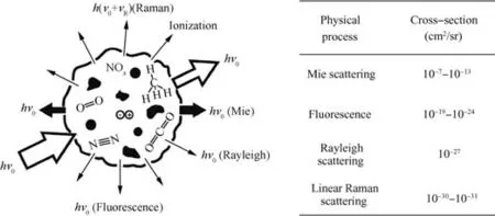
Fig.1 Schematic of different interaction processes between an irradiated laser beam and matter present in a sample volume(the table lists differential interaction cross-sections of some of these processes).2
Fig.1 illustrates different interaction processes2between an irradiated laser beam and matter present in a sample volume.The interaction cross-sections are applied to express the magnitude of achievable signal intensities in these processes.When a laser beam with frequency ν0irradiates into the sample volume,an interaction takes place between the incident laser and matter,such as solid particles,liquid droplets,or gaseous molecules.Such interactions lead to different forms of physical processes:(A)for Rayleigh scattering and Mie scattering,the radiation emission has the same frequency as the irradiated incident laser,i.e.,the elastic scattering process,and(B)for Raman scattering and laser-induced fluorescence,the irradiated photons and the matter cause a frequency shift,i.e.,first-order inelastic scattering processes.Under the same experimental conditions for different processes,the emission intensities are directly dependent on the magnitude of the interaction cross-section.It can be seen from the table in Fig.1 that the achievable signal intensities vary tremendously in magnitude among these commonly used laser diagnostics,and therefore often determine the choice of the best-suited diagnostics.
The velocity field is one of the most important parameters to describe motion in the combustion flow field.The Particle Image Velocimetry(PIV)technique,which is based on the imaging of the tracer particles illuminated by the incident laser,has experienced rapid development in recent years.The PIV technique has achieved great progress in terms of measurement principle,system implementation,practicalapplications,uncertainty analysis,and others.In particular,current computers with large memories are capable of speeding up data acquisition and evaluation,which has triggered an upsurge of the applications of the PIV technique for global velocity measurements.PIV technique has gradually grown from qualitative visualization to quantitative measurement of the flow velocity,which can be used to validate and assess numerical combustion models,and then gain deep insight into combustion flow fields.
In comparison with PIV measurements in a cold flow field,combustion measurements require a PIV technique adapted to severe testing conditions,such as high temperatures and pressures,as well as the presence of highly reactive substances.The PIV technique’s robustness must be sufficient to provide a large amount of velocity information in such extreme environments.Therefore,the applications of the PIV technique to combustion measurements not only rely on its inherent properties but also depend on the particular properties of the combustion process under investigation.Considering the difficulty of providing a complete and detailed overview to meet all the requirements of PIV measurements for complicated combustion flow fields,this paper focuses on several technical challenges that still need to be resolved,together with some practical applications.This review is also an introduction to the state of the art of PIV measurements in combustion and a discussion of some essential problems associated with combustion measurement applications.
2.Key issues for PIV measurements of combustion flow fields
To measure an accurate velocity field using the PIV technique,the following requirements must be met:3(I)Accurate tracking of the flow by the seeded tracer particles;(II)illumination of the tracer particles sufficient for photographic recording;(III)good focus across the camera’s field of view;and(IV)an appropriate number density of the tracer particles and time interval between the laser pulses.
Requirement I isessential for the tracer particles.Since PIV actually measures the speed of tracer particles,the particles w ith good flow tracking ensure the accuracy of the velocity field.This often requires a separate analysis of the tracer particles’response to flow motion,which ismostly dependent on the particle size,number density,and flow characteristics.Requirements IIand IIIare imaging related,and areespecially critical for small particles.Requirement IV ensures adequate tracer particles in the testing region for credible crosscorrelation calculations.Requirements II–IV directly determ ine the PIV setup,which is usually lim ited to a facility’s physical space and optical access.
Keane and Adrian4analyzed the effect of experimental parameterson a double-pulsed PIV system based on an analyticalmodeland M onte Carlo simulation,and then proposed the follow ing guidelines:A t least 10–20 particles should be presented inside an interrogation w indow;out-of-p lane motion of the particles in the laser sheet should not exceed 25%of the laser-sheet thickness;average particle motion w ithin the interrogation w indow should not exceed 25%of the w indow size;the variation of particle displacement due to velocity gradients should be less than 5%of the w indow size,so that the velocity vector w ill accurately describe the flow;and the acceptable threshold,i.e.,the ratio of the correlation peak to the ad jacentmaximum noise peak,should be set between 1.2 and 1.5 to detect a valid correlation peak in the correlation domain.
These requirements and guidelines can significantly improve the accuracy of PIV measurements.However,the application and development of PIV techniquesmust consider someother specific requirements for themeasurementsof combustion flow fields.
2.1.Tracer-particlematerial
Since a PIV technique determ ines the velocity field bymeasuring the displacement of the tracer particles,the selection of appropriate tracer particles is crucial.As for themeasurements of combustion flow fields,the tracer particles are more demanding in term s of being chem ically inert,i.e.,unable to react in a combustion environment,and possessing a high melting point to ensure good resistance to high temperature and avoid melting in the flame.M oreover,good particle dispersion and optical scattering are desired to obtain a high signal-to-noise ratio.From a safety pointof view,the particles should also be non-toxic,harmless,non-corrosive,and less contam inated.
From the current publications on the combustionmeasurements by PIV technique,tracer particles aremostlymonodispersed metallic oxides or silicate powders,such as SiO2,A l2O3,TiO2,and ZrO2;see Table 1.1,5–8SiO2demonstrates good scattering but a low melting point,while A l2O3has a high melting point but poor scattering.In contrast,TiO2has a higher melting point and better scattering characteristics,which provide the advantages of aerodynam ic response,costeffectiveness,easy operability,w ider availability,and has therefore become a prom ising choice for tracer particles in PIV measurements of high-speed flows.8–11Tuttle et al.8pointed out that the anatase form of TiO2has amuch lower Vickers hardness and a greater index of refractionnεand dielectric constantKe.The lower hardnessm inim izes the abrasion of observation w indows due to particle deposits and im pact,while the high dielectric constant ensures that static charges accumulated during entrainment and transport processes w ill not dissipate,making the particles disperse more easily.W hen the particles contact grounded surfaces,such as metal tubing and wall surfaces,they can easily dissipate any electric charge,thus reducing thenumber of particlesdeposited on the surface.Fru¨chtel et al.12also found that TiO2particles disappear in the flame front,and thus ZrO2may be another good choice under ultrahigh temperature conditions.
2.2.Flow-tracking characteristics
The basic assumption in a PIV technique is to measure tracer particle velocity as the fluid velocity,which is reasonable for incompressible flows at low speeds.However,an abrupt flow-velocity discontinuity appears due to the occurrence of shock waves in the supersonic flow,so that themotion of tracer particles cannot follow the flow deceleration.In addition,w ithin the strong expansion waves and vortex cores,tracer particles show a significant response delay resulting from the high gradient of the local flow velocity.These differences in velocity between the flow and tracer particles w ill lead to uncertainty in the velocitymeasurements,which is usually difficult to estimate.As a result,it is necessary to analyze the motion of tracer particles in PIV measurements.
U rban and M ungal13found that the relaxation time is approximately 3–4 μs for TiO2particles,while it isgreater than 20μs for A l2O3particles.Watanabe and M ungal14demonstrated thatan adequately small size and density of tracer particles are capable of entering the supersonic shear layer.Scarano and Van Oudheusden15claimed that the relaxation times of seeded TiO2particles are less than 2μs by analyzing the particles’motion across an oblique shock wave.Ragni et al.16also conducted systematic research on the flowtracking characteristicsby solid particlesw ith a relaxation timeof0.4–3.7 μs.These PIV measurements showed that submicron-scale/nanoscale tracerparticlesillustrate good tracking capability to capture the supersonic flows.

Table 1 Properties of commonly used metal-oxide tracer particles.
Chen et al.10,11analyzed particle motion in the flow based on the Basset-Boussinesq-Oseen equation,and then proposed a criterion of selecting appropriate particles in PIV measurements.11They pointed out that a sufficiently good flowtracking capability can be guaranteed when tracer particles are satisfied by the relationship of the relaxation time,Δt/τ=0.25–3,where Δtis the time interval between two laser pulses,and τ is the relaxation time that quantifies the particle’s response,which can be characterized in terms of the drag coeff i cientCD.Loth17developed a prediction model of the drag coefficient,which is supported by experimental and numerical results,to describe the flow physics around a particle.Considering compressibility and rarefaction effects which usually appear under supersonic simulation conditions,the tracer particles should be approximately 20–50 nm in diameter to ensure effective capturing of Mach 4 flow around a sharp wedge.11The images were recorded by a PIV system with a time interval of Δt=500 ns in PIV experiments conducted in the Multi-Mach-Number Wind Tunnel at Shanghai Jiao Tong University(SJTU),China.11
2.3.Seeding particles into the flow
To analyze the complex flow structures in combustion flow fields after selecting tracer particles with appropriate sizes and material properties,it is also crucial to ensure that the particles fully mix in the testing region.A uniform distribution with average diameter is expected for the particles seeding in the flow to track the flow and respond to changes in the flow continuum at the utmost.This is always accomplished by eliminating unfavorable interference from the pixel scattering of agglomerated particles and from the background noise of small particles.2However,these submicron-scale/nanoscale tracer particles have a strong tendency to form agglomerations several times larger than the primary size due to humidity or prolonged storage.For example,15-nm TiO2particles passing through an oblique shock wave would form agglomerations with an average diameter of 400 nm.13Al2O3particles are more likely to agglomerate,and 300-nm Al2O3particles would form 2–40-μm-diameter agglomerations.14These agglomerations sometimes abrade the observation windows and test models even impair the experimental facilities.
In supersonic and hypersonic flows,the changes in velocity cause a corresponding change in the number density of tracer particles;in particular,the number density becomes very high when tracer particles flow across a shock wave.18Seeding the particles upstream of the testing region is usually applied to make the particles disperse uniformly19,20The insufficient number of particles due to seeding in the large mass flow often leads to poor signal-to-noise ratio.21Therefore,particle dispersion determines the accuracy of PIV measurements,so that effective seeding and control of tracer particles becomes very important.Melling22summarized the commonly used particle-seeding techniques required to break or clear agglomerates as much as possible to provide relative uniformity of tracer particles without disturbances to the flow field.Appropriate particle-seeding methods are expected to control the size distribution and number density in the testing region,and should ensure that explosive gases are not ignited under any possible circumstances.
The main techniques for seeding solid particles into the airflow are the following:23,24
(1)Atomization.Solid particles can be dispersed in a liquid solvent,forming a suspension aerosol through the diluted spray to ensure no more than one particle in each droplet.After atomization,the liquid solvent evaporates,leaving only the solid particles in the seeding environment.25,26This method induces a certain flow-rate deviation,and the evaporation and cooling of the solvent may change the chemical reaction process,which is a reason that the method has not been used frequently.
(2)Use of metallic oxide powders.Such powders have a strong tendency to agglomerate,especially for the particles in the submicron range,and then they enlarge the particles and reduce the number density.The seeding devices should break or separate the agglomerates or coagulations before introducing the particles into the test section.27
Fig.2 shows two common seeding devices:the cyclone aerosol generator,22,28,29shown in Fig.2(a),and afluidized bed,shown in Fig.2(b),the most commonly used method in which a bedfluidizes the particles to aerate the space by the driven gas and then creates smaller particles that enter the experimental facility.Fig.2(b)depicts a simple seeding device with afluidized bed operated at high pressure,30–32which produces strong shear flows to break the agglomeration.A bypass line is used to maintain a constant mass flow rate into the facility,and the size of the outlet orifice is chosen to ensure a sufficient flow rate to carry the particles,fully mixed,into the testing region.
In addition,improving the flow tracking of tracer particles also requires that limitations,such as the wind tunnel facility,measurement devices,and flow conditions,be considered.Although particles of smaller size could improve the flow tracking,the ratio of the scattering intensity of particles to background noise due to wall-surface scattering and flame radiation will be too weak to accurately calculate the velocity field.In order to enhance the imaging quality of small particles,it is necessary to utilize a high-energy laser and highly sensitive cameras.
In order to successfully operatefluidized-bed seeders,the tracer particles are recommended to be hydrophobic and should be kept dry,preferably by heating and drying the material to remove extra moisture before filling the seeding device.It is also better to use dry air or nitrogen to operate the seeder,and to reduce the supply lines between seeder and facility to avoid a secondary agglomeration.Although researchers have made a series of improvements to the seeder structure,the control of particle concentration is still currently empirical,according to the measurement results.
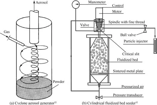
Fig.2 Commonly used solid particle seeder.
The seeding distribution system should not perturb the flow and,at the same time,should provide a homogeneous seeding level in the flow.This is usually accomplished by seeding the particles in the settling chamber,which is usually operated at high temperature and high pressure,to ensure that particles fully mix with the flow and to make the aerosol uniform in the test section.The injection pressure is required to be at least 1–2 MPa higher than that of the mainstream,thus ensuring successful particle seeding.The most commonly used seeding techniques are greatly challenged and unsuitable.Chen et al.11proposed and implemented a newly designed seeding system in combination with cyclone andfluidized-bed methods,as shown in Fig.3.This proprietary seeder can operate at a maximum pressure of up to 12 MPa driven by high-pressure dry air or nitrogen,thereby forming high-pressure cyclones full of high-momentum particles.The seeder was proven to be able to provide appropriate tracer particles in nanoscales for measuring high-pressure and high-speed flow fields.It was also found to be convenient for cleaning and filling particles by taking advantage of the operation process and time sequence.Accordingly,this seeder demonstrated distinct improvements in controllability of flow rate,rapid uniformity,and moisture-proofing ability.
2.4.Velocity bias due to particle-seeding nonuniformity
In order to reduce the disturbance to the flow- field measurements,the observation windows are required to properly identify tracer particles suspended in the flow.These windows must resist high temperature as well as high pressure due to combustion,which often results in a rather complex design.The PIV technique also faces a prohibitive challenge of window contamination due to particles adhering to observation windows.19,33Tracer particles build a static charge while colliding with walls and other particles,which leads to an attractive force toward the windows.The signal-to-noise ratio is weak due to the camera views through translucent windows and the light scattering from deposited particles.Therefore,the resultant decrease in the quality of PIV images degrades the measurement accuracy.34Additionally,the thermophoretic effect resulting from elevated temperatures can cause the particles to adhere to the windows,16,35thus making window contamination far worse.
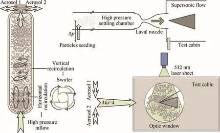
Fig.3 Particle-seeding system at SJTU.11
In order to abate window contamination,most combustion measurements only seed the tracer particles in the fuel,but not in the airstream,3,36–39through fuel injectors spraying into the testing region far from the observation windows.This nonuniform seeding method makes tracer particles rarely reach the window and keeps optical access clear.Smith36introduced particles into the fuel and then supplied them from the ramp fuel injector.The spreading angle of the fuel plume ensures that tracer particles are hardly close to the windows,but are only limited to a small measurement area,which cause large velocity errors.Regarding PIV measurements in cavitystabilized supersonic combustors,Tuttle38and Kirik et al.39seeded the tracer particles through the angled injector on the upstream wall,so that these particles were entrained into the cavity to capture the cavity flow.However,there may be a velocity bias,especially in the shear layer between the cavity recirculation zone and the mainstream,due to the absence of tracer particles in the mainstream.
Theoretically,tracer particles should be seeded in both the fuel and freestream to measure the entire region in a manner that avoids velocity bias.As shown in Fig.4,34in the case of the Dual-Mode ScramJet(DMSJ)at the University of Virginia(USA),there exists a high-speed freestream,a high-speed fuel jet core,and a lower-speed fuel/air mixing/combusting region.When tracer particles are only seeded in one stream,the region without particles would not acquire the velocity vectors and result in the velocity bias.Such velocity bias has an unfavorable effect on three-dimensional components,especially when there is a velocity gradient between two streams.40The tracers may not capture the flow structure on the mainstream side in the shear layer when only seeding in the fuel.Therefore,the mean velocity tends to be the velocity in the mixing/combustion regions with tracer particles.This velocity bias due to particle nonuniformity41,42is proportional to the gradient of particle number density.43,44Even if simply seeding particles in the two streams often reduces this error,the difference in the size or number density of tracer particles would still cause the velocity bias.This has motivated a number of researchers to propose some calibration methods.45–48
Researchers at the Supersonic Combustion Laboratory at the University of Virginia34conducted experiments with three seeding scenarios:only seeding the fuel,seeding both the fuel and freestream,and only seeding the freestream.This was the first study to qualify the velocity bias due to particleseeding,which significantly depends on the flow structures.As listed in Table 2,the effect of the seeding bias is relatively small since only seeding the fuel results in an average seeding bias error of 3.7%in mean velocity and 2.5%for the case of only seeding the freestream.For the Root-Mean-Square(RMS)velocity,the average errors induced by the seeding bias were 6.6%and 4.1%,respectively.In other words,seeding only the fuel can reduce window contamination and,furthermore,maintains validity in PIV measurements.
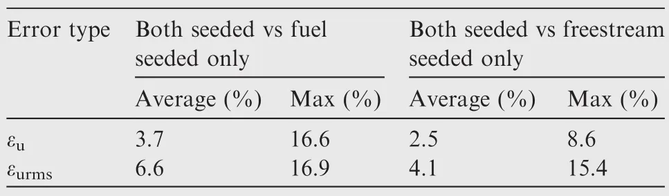
Table 2 Summary of absolute velocity bias error induced by different seeding cases.
2.5.Optical imaging aspects due to noise
Fig.5 shows PIV recordings of kerosene flame in a singlesector combustor.23The vertical stripes of significantly overexposed areas can be seen in the kerosene spray cone,which means that the high-intensity signal spreads the over flowing charge into neighboring pixels,i.e.,causes pixel blooming on the imaging sensor.This is because the scattering crosssection of rather large droplets(typically of sizes >50 μm)is significantly larger than that of micrometer-sized tracer particles.These vertical stripes cannot reflect the details of the actual flow field and thereby seriously degrade the imaging quality.Since the droplets evaporate in the flame,this overexposure is limited to the lower half of the image.In order to distinguish the droplet velocity from the gas velocity of this twophase flow,high-pass filtering and binarization of the acquired images are often used to match the intensity levels of the seeding with that of the kerosene droplets,such that areas normally biased to the droplet velocity could be corrected in favor of the gas velocity.30
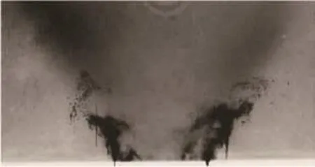
Fig.5 PIV recording of kerosene flame above a double-swirled fuel nozzle23(to enhance contrast,a negative image is shown;black areas are brightest).
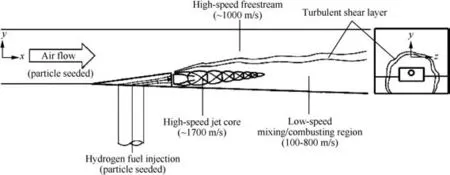
Fig.4 DMSJ flow structures and seeding schematic.34
While the atomized droplets evaporate near the flame in the upper half of Fig.5,the sensor saturation results from the highest flame luminosity.Moreover,in a double-exposure camera,the readout time of the second image is 50–100 times larger than that of the first image.Once glowing soot appears in the fuel-rich flame at elevated pressures,the narrow-band filters are not always sufficient for the suppression of overexposure due to strong luminosity.A more practical solution is mechanical or electro-optic shutters,ensuring the same read time of the image pairs.49
Furthermore,attention should be paid to the presence of background scattering light mainly from the test section and window surfaces,such as the circular window shown in Fig.5.23As the tracer particles are gradually deposited on the surfaces of the observation window,experimental model,and test section,the background noise not only reduces the overall contrast,but even leads to signal loss due to sensor saturation.The light traps and recessed windows somewhat reduce the problem,50but are not always effective.Additionally,the deposition of particles results in a stationary speckle signal,which makes measurements close to windows relatively difficult.
Image quality is ultimately determined by the integral distortion effects between the individual light-scattering particles and the imaging sensor.However,the light refraction along the imaging path due to temperature gradients inside and outside the combustion facilities lead to the displacement of the particle imaging on the sensor(similar to the Background-Oriented Schlieren(BOS)technique)and,even worse,a blurring of the particle image.This blurring can be roughly considered as a result of various factors,such as temperature,pressure,and penetration depth.It can be controlled to some extent by either of the following methods:23One method is to reduce steering by using zoom lenses to increase the distance between the recording lens and the optically disturbed media;the other is to reduce the size of the lens aperture to restrict all light rays to pass through similar refraction media,thereby resulting in a sharper image.The latter is particularly helpful to measure highly turbulent flows with locally strong modulations of density,but introduce more noise from the seeding deposits on window or walls due to the increased depth of field.It is,therefore,necessary to set reasonable operating parameters in PIV measurements based on the test facility and optical systems,and study their effects on the experimental results,thus eliminating the generated velocity bias as much as possible.
2.6.Post-processing
PIV data are vulnerable to background Gaussian noise,outliers,and missing data,which not only changes the visualization of the velocity and streamlines,but also greatly affects the quantitative analysis of the flow field based on differentiation,such as strain,vorticity,and vortex identification.Accordingly,post-processing algorithms are crucial before performing any analysis of the information provided by the PIV technique.Post-processing of PIV data typically consists of three consecutive steps:(A)Data validation,i.e.detecting outliers;(B)replacement of incorrect or missing data;and(C)data smoothing.Among these,the identification of outliers is the most critical procedure,and has received attention in many research papers.51–55
The global histogramfilter,the dynamic mean value operator,and the normalized median test are the most commonly used techniques in standard commercial post-processing software.However,most of the current outlier detectors require the use of thresholds whose selection remains somewhat arbitrary.An inappropriate threshold may result in undetected spurious vectors or eliminate valid data.The normalized media test can circumvent this drawback by using a single threshold,which is widely used in the calculations of PIV applications.55A median,bilinear,or spline interpolation is then generally used to replace the identified outliers.Since PIV data can also be altered by experimental noise,an average kernel of 2 pixel×2 pixel or 3 pixel×3 pixel is finally used to smooth the entire velocity field before any differentialoperation.56Recently,kriging interpolation,which is based on a ‘surrogate model”from the predetermined regression and correlation models,has been successfully applied to efficiently smooth and fill gaps in PIV data.57However,the amount of smoothness depends to some extent on the variogram parameter in the kriging procedure.
A PIV technique not only provides the velocity field,but ensures the credibility of the data.It is very important to eliminate invalid data and then to improve the accuracy of the analysis in post-processing procedures mostly related to the crosscorrelation algorithm.33In addition to the window shift technique58and other specific codes for turbulent flows,59the most direct progress made in cross-correlation procedures for PIV applications in supersonic and hypersonic flows is Window Displacement(and Deformation)Iterative Multigrid(WiDIM)processing technique proposed by Scarano and Riethmuller.60The WiDIM technique efficiently improves the accuracy in dealing with large gradient flows by varying the interrogation window size,which is especially useful in cases in which the seeding particles in the flow are non-uniform.Its capability has been demonstrated in the area of shock waves in the transonic and supersonic regimes,61as well as in hypersonic flows.19More recently,Theunissen et al.62also presented an adaptive PIV method that has shown excellent adaptability to local flow conditions,spatial variations,and seeding intermittency for PIV measurements in supersonic shock-wave-boundary-layer interactions.It can be seen in Fig.6 that the instantaneous sampling distribution is concentrated in those areas with sufficient tracers,and in the area where complex interactions take place and in which the window size is accordingly automatically scaled to a value ranging between 13 and 21 pixels.
3.Representative applications of PIV in combustion measurements
3.1.Supersonic combustor
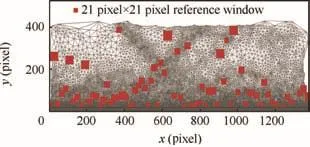
Fig.6 Unstructured mesh for a single snapshot of the instantaneous velocity field for a shock-wave-boundary layer interaction(squares represent selected interrogation areas).62
Weisgerber et al.63applied the PIV technique to measure the velocity field in a Mach 2 hydrogen/air supersonic combustor at ONERA’s LAERTE combustion facility(Paliseau,France).The acquired information,such as the development of boundary and shear layer and transient vortex structure,is consistent with the measured data of wall pressure and visualization images of the flame,and shows a good agreement with Laser Doppler Velocimeter(LDV)results.However,the research also exposed the problem that particle seeding is inherent and a necessary problem to solve in improving PIV techniques.
As shown in Fig.7,Goyne et al.64,65also found that the decrease of flow speed and increase of turbulence intensity resulted from heat release in a dual-mode scramjet combustor with an inlet Mach number of 2.It can be seen in Fig.7(b)that the fuel was sprayed from the ramp injection and then mixed with the freestream,which is depicted by a two-dimensional velocity field with a speed from 200 m/s(right bottom)to 2000 m/s(left).However,the tracer particles only seeded in the fuel cannot fully record the entire velocity field in this PIV measurement.
In supersonic combustion systems,the cavity plays a key role,which is conducive to the ignition and flame stabilization of the fuel in supersonic flows with small residence time.The cavity not only forms a recirculation zone to extend the residence time,but also produces a hot zone with continuous heat and radicals to promote combustion propagation in the mainstream.Moreover,supersonic combustion appears partially premixed due to the interference between upstream and downstream shock waves,which is dependent on fuel injection and flow rate.
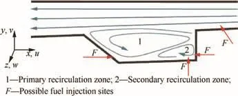
Fig.8 Idealized layout of cavity flow with streamlines.8
Fig.8 shows the fuel injection in several ways.Tuttle et al.8used 100-nm-diametersphericalTiO2powderastracer particles to achieve uniform particle distribution with slight aggregation and window contamination.These particles were seeded in the low-momentum boundary layer of the isolator,moved into the shear layer between the cavity flow and the mainstream,and then entrained into the cavity to simultaneously measure the flow structures in the flow field of concern where the wide speed range and large velocity gradient greatly challenged the PIV measurements.PIV measurements acquired the distribution of streamlines and averaged values of velocity magnitude,Reynold stress,and vorticity in the cavity,as shown in Fig.9.The information can be used to analyze the position and intensity of vortex structures and help to understand the formation,transport,and dissipation of coherent structures.The results also demonstrated that the convective Kelvin–Helmholtz instability in the shear layer was influenced by the instantaneous impact of the shear layer on the cavity,which is helpful to gain insight into the transport of combustion stability and flame propagation.
In view of three-dimensional characteristics in the DMSJ flow field,Smith et al.66introduced three-component or Stereoscopic PIV(SPIV)to measure three components of the velocity field.They seeded 0.3-μm Al2O3particles in the fuel through afluidized-bed seeder and then sprayed the fuel plume into the combustor via ramp injections.The application of the SPIV technique is difficult due to the high-temperature environment,large axial velocities,and a very narrow optical access.Although the problems are very complex,Smith36applied the SPIV technique to obtain the velocity field of the DMSJ combustor.This was the first time the counterrotating vortex pairs induced by the ramp injections were acquired.Fig.10 compares the flow field of fuel-air mixing and combustion,and reveals that the average speed after burning decreases due to the heat release that makes the turbulence stronger.Therefore,Computational Fluid Dynamics(CFD)simulations should carefully consider the combustion effect by selecting the numerical algorithms and methods suitable not only for mixing,but also for the combustion flow field.
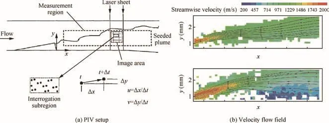
Fig.7 PIV setup and velocity flow fields of DMSJ combustor.64,65
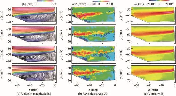
Fig.9 Streamlines and averaged values of velocity magnitude,Reynolds stress,and vorticity.8
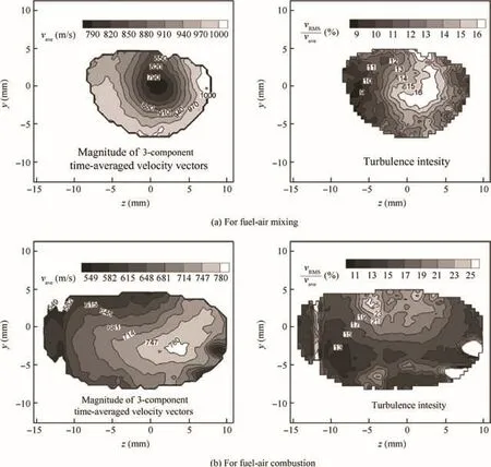
Fig.10 Results for fuel-air mixing and combustion at x/H=10 in the DMSJ combustor.36
3.2.Swirling burner
In combustion systems,swirling motion can strongly enhance the mixing between fuel and oxidant streams and to improve flame stabilization through the swirl-induced recirculation of hot products.Therefore,the application of swirl is an aid to the stabilization of the high-intensity combustion processes and efficient clean combustion in a variety of practical situations,such as aeroengines,gas turbines,internal combustion engines,and industrial furnaces.The performance and ef ficiency of swirling burners depend on thefluid dynamics of the mixture.
However,the highly three-dimensional nature of the flow in a swirling burner poses a significant challenge to any diagnostic measurement technique.The presence of vortex structures makes it difficult for the tracer particles to track the flow in the measured plane.The complex region with different velocities in the flow structures also strongly affects the uniformity of particle number density.The requirements for tracer particles in different areas are not the same,so the particle seeding becomes very complex.As for the swirl flow with a large component of tangential velocity off the laser sheet,the resultant off-plane errors should be taken into consideration.
Chen et al.applied TiO2tracer particles in nanometer scales in combination with a unique particle seeder11to effectively solve the problems of window contamination,wall scattering,and off-plane errors.It was the first time clear flow structures were acquired in a swirling burner by elaborately setting PIV system parameters.The results shown in Fig.11 demonstrate that the nanometer-sized tracer particles have excellent flowtracking performance,and thereby effectively capture and quantitatively measure various vortex flows with appropriate particle density.
In order to completely characterize the flow field,Olivani67used double seeding:Silicone-oil droplets with a mean diameter of 1 μm were seeded in the fuel flow,while Al2O3particles with a mean diameter of 5 μm were seeded in the swirl air flow.An appropriate interrogation window and a laser pulse delay were selected in order to avoid tracer particles going out of the boundary.The high melting temperature of Al2O3is suitable for measuring the velocity field not only inside reactants,but also inside the flame region and combustion products.By analyzing different mixing mechanisms between coaxial and radial fuel injection,68it was found that the Precessing Vortex Core(PVC)instability occurred in the flows with high Reynolds and swirl numbers,and was characterized by the regular precessing vortex core around the geometric axis of symmetry.
Fig.12(a)68gives the streamlines acquired by PIV measurements superimposed on the flame image.Clearly shown are the fuel jet,the Central Toroidal Recirculation Zone(CTRZ),and the Corner Recirculation Zone(CRZ).The CTRZ is the broad region of reverse flow extending back toward the burner head,which is confined by the expanding air stream.This vortex breakdown is attributed to an unsteady phenomenon occurring at high swirl numbers(>0.6).The CRZ is confined to the chamber wall and the bottom plate,and then extends externally to the air stream until it is partially outside the PIV field of view.A toroidal structure induced by the entrainment of the fuel jet on the surrounding stream is helpful to control the fuelair mixing at the inlet of the combustion chamber.Fig.12(b)68gives the flow structures in the case that the fuel is transversally injected,and the fuel jet does not interact with the formation of the CTRZ.By comparing the different fuel injections,the reverse- flow region carrying hot combustion products moves upstream closer to the reactants outlet,thereby enhancing the mixing between reactants and products.Such mixing improvement provides energy for the ignition of the fuel-air mixture and clearly forms the region of fuel recycling and high vorticity,which has been recorded very well by the PIV technique.
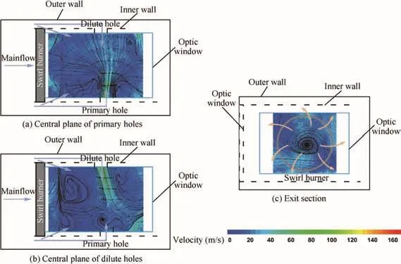
Fig.11 Velocity flow fields of several planes in a swirl burner.

Fig.12 Superimposition of streamlines and picture of a non-premixed swirl flame.68
4.Development trends of PIV techniques for combustion measurements
Along with gradual increases in complexity and difficulty of measured combustion flow fields,PIV techniques for combustion measurements have been significantly developed,and new trends have emerged.
4.1.Three-dimensional PIV
The combustion flow field involves strongly complex threedimensional non-stationary flows due to the occurrence of the flow separation and vortex.The analysis of a threedimensional or three-component velocity field is crucial in understanding such a combustion flow field and flow structures.The measurement of these three-dimensional characteristics,especially important to turbulence research,can reveal the topology of turbulent coherent structures and contribute to the validation and improvement of CFD models,which also require the measurement of the three-dimensional and threecomponent velocity field.The PIV technique,which has been extended from the measurement of a two-dimensional plane to three dimensions or three components with different viewing angles for quantitative measurements of complex flow field,68involves scanning PIV,holographic PIV,stereoscopic PIV,and tomographic PIV,among others.
Scanning PIV69can be used to reconstruct a quasiinstantaneous flow structure from PIV recorded images over a series of slightly shifted planes obtained at high repetition scanning rates.With continuous advances in high-speed cameras and scanning apparatus,scanning PIV can provide high spatial resolution at repetition rates of several hundred Hz,70butcannotyield trulysimultaneousdata.Holographic PIV71,72is capable of measuring the instantaneous threedimensional velocity field,achieved through construction by holographic recording of an illuminated volume,while digital planar holography and its implementation is very complex and thus has not yet been widely accepted.Therefore,in this paper we mainly discuss the rapidly developed and relatively mature Stereoscopic PIV (SPIV)and Tomographic PIV(TPIV)techniques.
4.1.1.Stereoscopic PIV(SPIV)
Rice et al.37summarized the application of the Stereoscopic PIV technique in DMSJ research to analyze particular quantities,such as the instantaneous velocity,average velocity,vorticity,turbulence intensity,turbulent kinetic energy,and Reynolds stress.Since the flow in a scramjet combustor is highly three dimensional,these measurements are conducive to providing insight into complex flow structures,to enhance the development of fuel-air mixing and combustion techniques,to improve combustion performance and control the transition of combustion mode,to validate numerical models and facilitate comparison with flight-test results,and thus to construct a comprehensive baseline database to support the numerical simulation of the complex flow fields inside such a combustor section.
As shown in Fig.13,37SPIV is much like binocular vision imaging,which utilizes two separate cameras at an angle to simultaneously record the images of the flow in the same laser-illuminated region.Two pulses of planar sheets with a small time interval from a Neodymium-doped Yttrium Aluminum Garnet(Nd:YAG)laser are applied to illuminate the injected seeding particles within the measurement volume,and the high-speed Charge-Coupled-Device(CCD)cameras capture the particle shift.The measurement of both in-plane and out-of-plane particle displacements are gained by two camera views from different perspectives.The three components of velocity field are determined by combining the twodimensional velocity components identified by each camera through a predetermined mapping function.This function,which maps positions from image space to the physical space used in the two-dimensional(2D)PIV measurements,must be calibrated because of the perspective distortion caused by the angle of the cameras in a 3D PIV measurement.This is performed by dividing the measurement area into smaller interrogation sub-regions in which a statistical cross-correlation method determines the most likely displacement in which one peak exists that corresponds to the displacement.In the post-processing procedure,uncorrelated particles arefiltered out as noise.
Fig.13 SPIV experimental setup.37
SPIV is particularly useful when applied to combustion measurements,because it is able to provide both instantaneous and time-averaged,3D,spatially resolved measurements.In addition, flow parameters such as vorticity,Reynolds stress,fl uid strain,divergence,turbulent kinetic energy,and turbulence intensity can be determined.These measurements not only help to understand the complex flow structures,but are used to compare against and validate computer models.It should also be noted that SPIV additionally provides the out-of-plane velocity component,thereby giving access to two further velocity gradient components;however,these do not provide any additional strain rate or vorticity components.24
In the calibration procedure,although each of the two cameras unnecessarily identifies the cross-shapedfiducial mark at the exact same location in their respective image,the reference point must be positioned as close as possible to the center of the field of view of each camera.This is very crucial to maximizing the area of the calibration target that is viewed by both cameras where 2D vectors can be combined to form 3D vectors.Several experimental trade-offs should be considered to select appropriate camera positions in case of signal degradation and magnification,in addition to the limitation of window size and position of the test section.If the measurement plane,lens plane,and image plane all intersect at a single point,the image can be in sharp focus across the field of view despite still being distorted by a tilting image plane.This Scheimpflug condition is therefore essential to be satisfied to guarantee a high accuracy for imaging.
4.1.2.Tomographic PIV(TPIV)
In contrast to stereoscopic PIV,Tomographic PIV(TPIV)distinctively utilizes a three-dimensional volume to replace a planar projection as a measured domain.Based on the principles of optical tomography,tracer particles are illuminated by a three-dimensional laser,and then simultaneously captured from different viewing directions by several cameras.In brief,TPIV is a three-dimensional measurement technique involving particle imaging,a reconstruction algorithm,and crosscorrelation analysis within a measured volume.This approach has rapidly been adopted as a versatile,robust,and accurate technique to investigate three-dimensional flows.Scarano73reviewed the major developments in three-dimensional velocity field measurements using the TPIV technique,and the working principle is schematically shown in Fig.14.
The tracer particles dispersed in the flow are illuminated by a pulsed light source within the measured volume generated by expanding the thickness of the light sheet to a typical depth of 25%width or length of the field of view,thereby requiring higher energy than planar PIV experiments.After distributing the laser light over a larger region,the shortage of energy density may require some special arrangements to optimize the illumination.As illustrated in Fig.15(the definition of parameters appears in Fig.15 are originated from Ref.73),the multi-pass light amplification system73sends the circular light beam with a small angle into a region bounded by two highly reflective mirrors(reflectivity higher than 99%).From that point on,the beam is reflected back several times towards the exit following the same optical path.It is important to increase the scattered light intensity from tracer particles for the TPIV system.
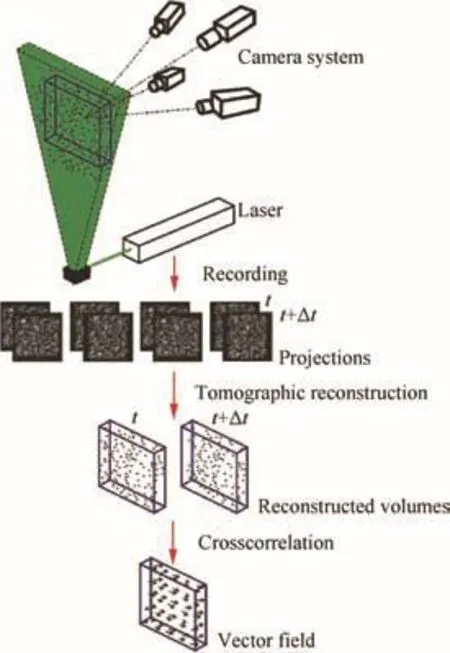
Fig.14 Working principle of TPIV.73
The quality of tomographic PIV measurements is greatly determined by the tomographic imaging system design.It consists of several cameras viewing the illuminated region from different directions,and is used to collect the light scattered from the tracer particles.The application of lens-tilt adapters with two degrees of freedom ful fills the Scheimpflug condition between the image plane,lens plane,and mid-object plane.The imaging system requires a relatively long focal depth to record the particle images in focus by increasing the numerical aperture of the objectives until the focal depth is matched to the thickness of the illuminated volume.The most popular configuration is placing four cameras along the vertices of a pyramid due to the minimum requirement in terms of the angular aperture of the system.As shown in Fig.16,a cross-like configuration has a similar effect,with the advantage of an easier setting of the lens-tilt adapter(the lens plane rotates vertically or horizontally).In some cases,in which the outer cameras must be set to a large viewing angle(e.g.,Fig.15,right),an arc-like system will be applied by placing all cameras along a line.More extended opticalaccessasplacing allcamerasin the forward-scattering direction usually requires that the object must be viewed from opposite sides.
As a consequence,a series of recorded images are the input to the reconstruction algorithm.The 3D particle distribution is then reconstructed through a 3D light intensity distribution obtained by imaging arrays,which is usually accomplished using the Multiplicative Algebraic Reconstruction Technique(MART).73The tomographic reconstruction is based on an accurately established relation between the image(projection)coordinates and the physical space(the reconstruction volume)through a calibration procedure,which requires significantly stricter precision than that used for SPIV.74In the interrogation windows,the analysis of the particle motion(velocity)within the object pair is performed by 3D cross-correlation.The algorithm based on WiDIM60,75has been extended to three dimensions.
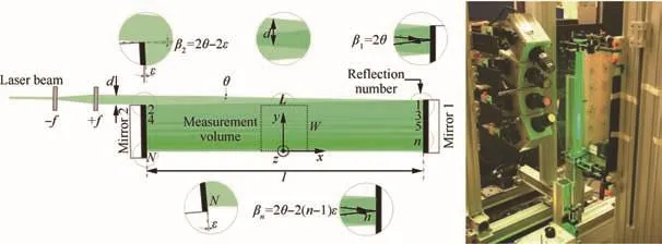
Fig.15 Description of multi-pass light amplification system for TPIV and application of multi-pass light amplification to trailing-edge measurements by time-resolved TPIV(right).73
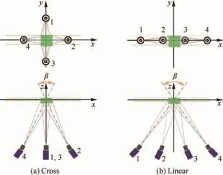
Fig.16 Cross-like(left)and linear(right)imaging configurations of TPIV systems based on four cameras.73
Baum et al.76applied TPIV within a motored Direct-Injection Spark-Ignition(DISI)optical engine to measuring an instantaneous volumetric flow field at different Crank-Angle Degrees(CADs)during the intake and the compression stroke.However,the application of TPIV in Internal Combustion(IC)engines has been greatly challenged by the limitation of optical access,the physical space surrounding the engine,a thickly curved glass cylinder causing optical aberration effects,engine vibration,etc.The measurements shown in Fig.16 were conducted using a double-pulsed Nd:YAG laser with an average pulse energy of 375 mJ for illumination and four CCD cameras arranged circularly from different perspectives around the optically accessible cylinder.
This paper details the first assessment of TPIV measurements of instantaneous flow field in a single-cylinder DISI engine.The fluctuations of the 3D flow field can be characterized by the Turbulent Kinetic Energy(TKE),as shown in Fig.17.The measured flow field well explained the differences in the occurrence and orientation of strong vortex structures for the ensemble-averaged and instantaneous cycles during the intake and the compression stroke.The results demonstrated the capability of TPIV for particle reconstruction and volumetric cross-correlation,with image distortion caused by the thick curved glass and limited camera angles.Therefore,TPIV is feasible for the measurements of the 3D flow field in an internal combustion engine and thus feasible to provide databases for the validation of the large-eddy simulation of combustion.
Although the optical configuration of TPIV is relatively simple and very similar to SPIV,TPIV is capable of handling the flow field with relatively high particle density and ensuring the robustness of the measurements with higher requirements for post-processing programs in combination with imaging and reconstruction.In brief,TPIV is so attractive as to be highly likely to become a reference technique for 3D measurementswith respectto SPIV for3-Component(3C)measurements.
4.2.Using high-temporal/spatial-resolution devices
Combustion processes that usually take place in thin,sheetlike regions( flame)are characterized by extremely spatially inhomogeneous features,while turbulent combustion shows highly instantaneous features.As for most practical combustion systems,the flame has a thickness on the order of some tens to hundreds of microns.Combustion also involves broad timescales:some relevant chemical reactions occur within a few nanoseconds,while many reaction intermediates that play key roles in combustion chemistry only exist in a very short timescale,ranging from hundreds of nanoseconds to microseconds.Therefore,the investigations of the dynamic processes of these tiny structures have defined the requirements to be of high spatial and temporal resolution.
Table 32shows the governing time and length scale estimates for some combustion applications from the molecular scale to the combustor size in meters,from molecular vibration to the system time.These characteristic scales impose high demands on the desired temporal and spatial resolutions of the diagnostic techniques.However,a general high-energy laser only has a repetition frequency of 100–300 Hz,including Q-switched solid-state lasers(e.g.,Nd:YAG lasers)or gaseous lasers.With the development of lasers and cameras,high-speed imaging of turbulent flame has become possible.77It is important to investigate time-dependent combustion phenomena,such as the vortex- flame interaction and local extinction,78–80which have endowed PIV with the capabilities of high-speed sampling on the order of kHz81–83and of velocity field measurements in engine cylinders.84
Researchers at Ohio State University(USA)85,86have developed a new generation of the High-Energy Pulse Burst Laser System(HEPBLS),as shown in Fig.18.It can generate pulse energies greater than 2 J/pulse at a wavelength of 1064 nm with inter-pulse separations of 50 μs(i.e.,repetition rates of 20 kHz)for burst durations exceeding 100 pulses,which can provide strong support to turbulentfluid dynamics/combustion and high-speed flow measurements.There also has been considerable progress in the design and manufacturing of Complementary Metal-Oxide Semiconductor(CMOS)cameras,which mainly have the following advantages:high repetition without streaking,low power consumption,easy integration,flexible usage,and strong resistance to irradiation.The exposure time and pattern can be freely controlled within a certain range due to theflexible control of the reset time sequences.The development of high-energy pulse burst lasers and CMOS cameras promotes the time-resolved PIV techniques,which are capable of acquiring the time-dependent terms of velocity field for high-speed ground test facilities.
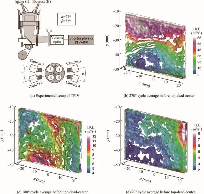
Fig.17 Experimental setup of TPIV measurements in optical engine and 3D iso-surfaces of TKE.76
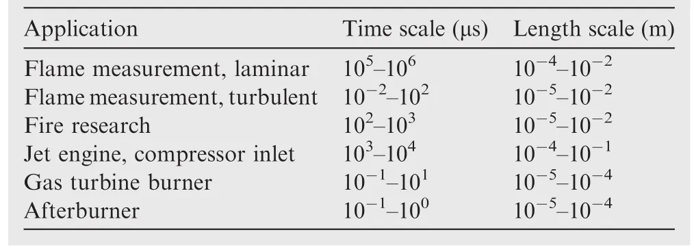
Table 3 Time and length scales of some different combustion systems.2
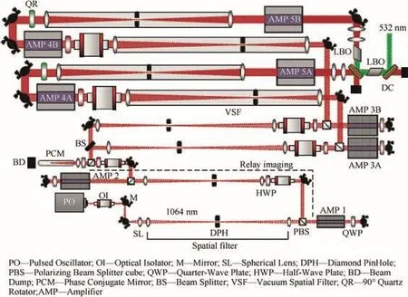
Fig.18 Schematic of new HEPBLS(dashed line connects the ‘endpoints” of a single relay image pathway,the configuration depicts the inclusion of a second-harmonic doubling LBO(lithium triborate or LiB3O5)crystal).85
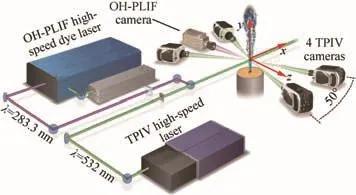
Fig.19 Experimental configuration for simultaneous high-repetition-rate TPIV and OH-PLIF imaging for studying turbulent flame dynamics.87
Workers at Sandia National Laboratories(USA)87realized simultaneous PIV/OH-PLIF(where PLIF denotes Planar Laser Induced Fluorescence)measurements at an acquisition rate of 20 kHz,as shown in Fig.19,which can identify the evolution of vortex structures in the jet mixed layer.Their results demonstrated that the vortex structures exhibittimedependent morphological changes and eventually dissipate when approaching the flame.Compared with the constantdensity,turbulent,non-reactive jet(i.e.,Case 2NR),the jet flame(Case 2)has larger coherent structures that are confined near the reaction zone,as shown in Fig.20.These advanced devices have improved the measurement frequency of PIV technique by 3 orders of magnitude,thus making it possible to capture the rapid changes in the tiny combustion structures,such as extinction,ignition,and reignition.Accordingly,PIV techniques can be applied to high-frequency measurements in practice,and,to some extent,can complement traditional combustion measurements to reveal the possibly missing information.However,there are still many challenges to the wider application of high-temporal-and-spatial-resolution devices,including high cost,complicated maintenance,and some limitations of the test section and optical access.
4.3.PIV combined with other optical diagnostics
Combustion processes include fuel-air mixing,atomization,combustion,pollutant formation,and turbulence/reaction interactions.As combustion complexity increases with further investigations,it is difficult to meet the requirements of multiparameter measurements with just a single diagnostic to gain insight into the variation of flame structures with species concentration and turbulence intensity.In addition,the strong interactions between reactive flow and heat release require the simultaneous measurements of velocity and the other scalar parameters to validate and improve the numerical model.This multi-parameter simultaneous measurement is expected to lead to a better understanding of instability, flashback,local extinction,and pollutant formation,etc.
With the development of flame visualization,spectral information,and high-speed imaging,it is possible to combine PIV with other optical diagnostics in combination with advanced lasers and multi-camera imaging systems so that true synchronized combustion visualization and quantitative multiparameter measurements are realized.88The combination of PIV with one or more diagnostics will greatly extend the applicability of PIV techniques,and thereby will become an important means of promoting combustion science and technology.Since PLIF can qualitatively display the flame front and measure species concentration or temperature with high temporal and spatial resolution,the combination of PIV with PLIF has attracted much attention in the measurement of flame velocity and scalar quantities.
For example,Watson et al.89conducted simultaneous measurement of 2D velocity fields by PIV and realized a visualization of the flame front characterized on the fuel-rich side of the reaction zone by CH-PLIF.A schematic representation of the experimental setup for simultaneous PIV/CH-PLIF measurements is shown in Fig.21.The laser sheets were oriented to illuminate an axial slice through the centerline of the flow,and the two detectors were aligned so that the same region of the flow was imaged by simultaneous measurements.Both the air and methane streams were seeded with tracer particles of Al2O3with an average size of 0.5 μm,while two colors(red:616 nm;green:532 nm)were used to eliminate any directional ambiguity.
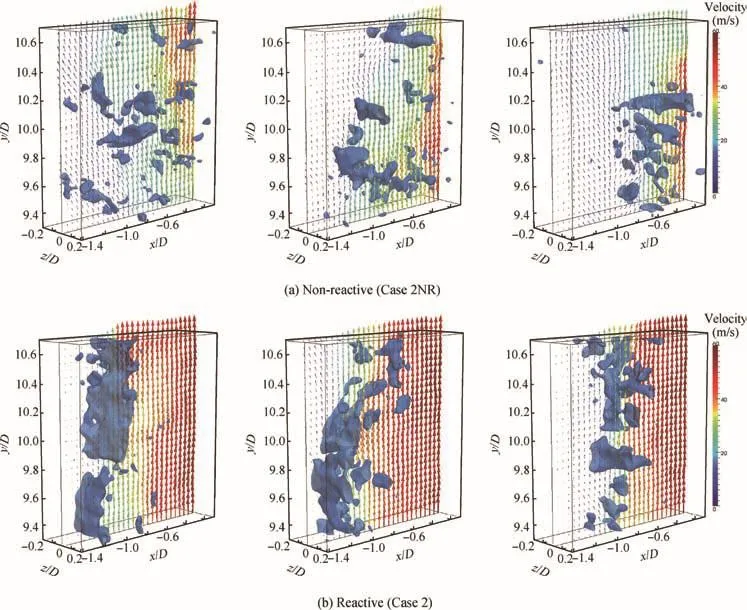
Fig.20 Comparison of vortical structures in non-reactive(Case 2NR)and reactive(Case 2)turbulent jets at y/D=10(surfaces are enstrophy iso-surfaces for squared divergence ω2=500 × 106s-2,velocity vectors are displayed in the mid-plane at z=0(one out of 16 in-plane vectors displayed)).87
Fig.22 shows the CH fluorescence image overlaid with a 2D velocity field acquired by PIV measurements.It can be seen that the combustion is locally extinguished on the base of the lifted flame,where the CH radical field appears open.The formation of an internal vortex may cause this occurrence,pushing the flame outward while flow enters the flame through the opening of the CH signal.These vortex- flame interactions result in the quenching of exothermic reactions,heat reduction,and local flame extinction when the internally generated vortices continuously penetrate the reaction zone and lead to the steep fuel concentration gradients with excessive fuel fluxes into the flame front characterized by the CH signal openings.Thissimultaneousscalar/velocitymeasurementtechnique reveals the influence of velocity field on the reaction zone,further illustrating that the vortex/ flame interaction plays an important role in local flame extinction.Watson90and Lyons et al.91therefore conducted investigations on the local flame structure.
By using a simultaneous PIV and OH-PLIF technique,Rehm and Clemens92directly investigated the relationship between the reaction-zone structure and the underlying strain and vorticity fields while both the main flow and co- flow were seeded with 1-μm Al2O3particles for PIV.Furthermore,Boxx et al.93implemented the synchronization of OH-PLIF imaging and PIV velocity measurements with 500-nm TiO2tracer particles and clearly revealed the interactions between the reaction zone and the flow field.Bo¨hm et al.80designed a simultaneous PIV/PTV(Particle Tracking Velocimetry)/OH-PLIF measurement system that applied a double-pulsed PIV/PTV technique to capturing the velocity field with 1-μm MgO tracer particles,while OH-PLIF was used to record the flame structure and species concentration.Tanahashi et al.94measured the velocity field and two radical concentrations in a stable swirling ethylene–air flame using the simultaneous SPIV/CH/OH-LIF technique.Filatyev et al.95also simultaneously applied SPIV measurements of 3D turbulent fluxes together with two separate acetone-LIF visualizations of the flame front motion.

Fig.21 Simultaneous PIV/CH-PLIF experimental arrangement.89

Fig.22 Simultaneous PIV/CH-PLIF measurement from boxed region of top figure.90
Accompanying a velocity field acquired by PIV,Ma et al.96proposed a multi-angular flame measurement method based on Fiber-Based Endoscopes(FBEs).The FBEs areflexible,small,and very convenient for use in a small space.The measurements can capture the flame dynamics from different angles(e.g.,the top and both sides)simultaneously onto the same camera chip,greatly reducing the equipment cost for the measurements.The experiments were conducted in the supersonic wind tunnel at the U.S.Air Force Research Laboratory.Fig.23 shows the overall setup position relative to the test section of the customized FBEs from the cross-sectional view of the tunnel.The chemiluminescence sensors with one fiber-based output and four fiber-based inputs can capture four images using a single camera.A set of chemiluminescence images such as those shown in Fig.23 at multiple angles in combination with velocity field measurements are expected to provide further insights into flame dynamics and flow structures in high-speed propulsion systems.
The introduction of these methods into combustion measurements is conducive to better understanding the combustion region with various turbulence and spatial scales despite some challenges such as optical layout,thermal protection,and high cost.The extension of these applications has partially solved some of the practical difficulties in tolerating higher temperatures with lower cost.Therefore,the combination of PIV and other optical diagnostics has gradually become a popular method for measuring combustion flow fields,with more information to support the numerical modeling and design optimization of combustion systems.
4.4.Close-collaborative experimental and computational study
As combustion problems and their measurement techniques are becoming increasingly sophisticated,meeting the requirements for problem description and physical modeling has become urgent.Clearly,experimental study and numerical simulation can be complementary,but one cannot replace the other.The possible interactions between diagnostics,theory,and modeling in combustion are illustrated schematically in Fig.24.2Taking into account the entire system,modeling requirements,and the interactions of measurement objects and boundary conditions,close-collaborative experimental and computational study has become a general trend.CFD simulations not only rely on some isolated experiments,but also on a relatively comprehensive set of high-resolution data.Moreover,the PIV technique not only evaluates the applicability and accuracy of numerical methods,but also contributes to the exploration of the details of flow structure and to the development of physical modeling.Close collaboration on a variety of research initiatives in different areas is expected to lead to the acquisition of complete and valid data to accurately describe the objects of research.

Fig.23 Schematic of experimental setup for multi-angular flame measurements using fiber-based endoscopes.96

Fig.24 Some interaction mechanisms between diagnostics,theory,and modeling in combustion studies.2
One excellent example of the close collaboration between diagnostics,CFD,and modeling is the workshop series on Turbulent Non-premixed Flames(TNFs),which has successfully brought experimental and computational researchers together to promote the development of turbulent combustion.The benefit of such workshops is that all the research is focused on the embodiments in one or more baseline flames by exchanging the measurement and calculation information for the development of modeling,design,and diagnostics.For example,the breakthrough of using the Probability Density Function(PDF)model in the numerical simulation of local extinction in turbulent non-premixed flames97–99is one of the workshop’s most prominent achievements.
In order to gain significant insight into the items of specific interest,including shock-boundary layer interactions,finite rate chemistry,turbulence/chemistry interactions,and ignition/ flame stabilization in the combustor,wall separation and turbulence in the isolator,and reactant mixing,Rockwell et al.100proposed a close-collaborative study by bringing experimental and numerical efforts together.The loop shown in Fig.25 includes experiment,Finite-Element Analysis(FEA),and CFD,which leads to the development of a detailedfinite-element model to understand the thermal-mechanical behavior of the test section hardware,while preliminary CFD results provide boundary conditions for the FEA and,in turn,guide experimental hardware improvements.
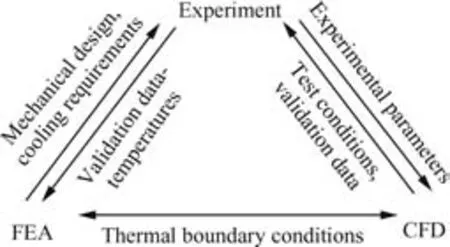
Fig.25 Experiment-FEA-CFD close-collaborativefeedback loop adopted in present study.100
The experimental database includes surface pressures,wall temperatures,focused Schlieren imaging,SPIV,Tunable Diode LAser Spectroscopy(TDLAS),Coherent Anti-stokes Raman Scattering(CARS),and PLIF.The numerical modeling consistsofboth time-averaged Reynolds-Averaged Navier-Stokes(RANS)and time-accurate hybrid Large-Eddy Simulation (LES)/RANS approaches.Thiscollaborative research builds a bridge between experimental data and numerical modeling in a way that the experimental database provides the maximum benefit to the numerical modeling effort and vice versa.It also is a significant step in improving the measurementfidelity and the numerical modeling involving high-temperature and high-speed combusting flows.It is particularly valuable for the selection of the experimental flowpath geometry,diagnostics,and measurementlocations design,to provide a characterization of scramjet combustor operation and performance for the design improvements incorporated into the physical test hardware.
5.Conclusions
It can be seen from the aforementioned key issues and applications that the PIV technique based on tracer particles has reached a high degree of maturity starting from professional tool and expanding to wide utilization over the last several decades and has made significant developmental progress:
(1)The development of lasers,cameras,and fiber-based endoscopes significantly improves spatial and temporal resolution,so that PIV can measure spatially and temporally resolved velocity fields and capture instantaneous combustion processes,such as local extinction and ignition.
(2)By combining PIV with other optical diagnostics,such asPLIF,simultaneousmeasurementsofmultiple parameters,such as velocity,species concentration,or temperature,can be implemented to gain insight into combustion flow fields and even into the control of combustion processes.
(3)PIV data can be applied to numerical modeling of combustion mechanisms with a wider range of conditions through reasonable extension and summarizing,while verified numerical simulations can be used to assess the accuracy and capabilities of PIV techniques.
PIV for future combustion measurements involves more sophisticated research objects and more practical applications.As for the new design of PIV measurement systems,more complex limitations of the testing environment,optical layout,and other factors should be considered.The practical applications of PIV measurements will continuously promote its capability and applicability:
(1)Obvious improvements have been made to the seeding technique for high-temperature-resistant solid tracer particles,e.g.,the tracer particle seeder at SJTU.Additional efforts should be made to improve the controllability and stability of particle density,and thus prevent the unfavorable effects of background noise and window contamination.
(2)With respect to the massive amount of PIV data,analysis,post-processing,and storage are expected to be effective,easy,and convenient within a considerably short time.In addition to the improvements in the accuracy of PIV images,there are still challenges to rapidly automate algorithms for application and extend PIV measurements to combustion flow fields.
Now that PIV has a considerablefine capability to measure combustion processes at small scales through numerous replicable measurements,it has gradually become sufficiently robust to be applied to large-scale combustion devices.Further development of optical instruments,analysis software,and particle seeders is expected to meet the requirements of higher accuracy,resolution,and signal-to-noise ratio for large-scale combustion measurements.
Acknowledgements
The authors acknowledge the support from the National NaturalScienceFoundation ofChina(Nos.11672183,91641129 and 91441205).The experiments of swirling burner were supportedbyAirbreathingHypersonicLaboratory(AHL)of China Aerodynamics Research and Development Center(CARDC).
杂志排行

CHINESE JOURNAL OF AERONAUTICS的其它文章
- Abnormal changes of dynamic derivatives at low reduced frequencies
- A new hybrid aerodynamic optimization framework based on differential evolution and invasive weed optimization
- Experimental study of an anti-icing method over an airfoil based on pulsed dielectric barrier discharge plasma
- Envelope protection for aircraft encountering upset condition based on dynamic envelope enlargement
- Effects of the radial blade loading distribution and B parameter on the type of flow instability in a low-speed axial compressor
- Adaptive sliding mode control for limit protection of aircraft engines