Envelope protection for aircraft encountering upset condition based on dynamic envelope enlargement
2018-07-24WujiZHENGYinghuiLIDengchengZHANGChiZHOUPengweiWU
Wuji ZHENG,Yinghui LI,Dengcheng ZHANG,Chi ZHOU,Pengwei WU
Aeronautics Engineering College,Air Force Engineering University,Xi’an 710038,China
KEYWORDS Differential manifold theory;Dynamic envelope;Flight safety;Loss of control;Region of attraction
Abstract Upset condition encountered by an aircraft in flight could pose great threat to flight safety,which is of chief importance in civil aviation.The causal factors have the nonlinear and multiple characteristics,and as a result the conventional envelope protection system cannot successfully do with the condition.So dynamic envelope based on differential manifold theory,which can take more coupling factors into account,is proposed as a basis to design a novel envelope protection system.Then the relationship between the dynamic envelope and the control coefficient or pilot command is obtained,and the result shows that the dynamic envelope can be enlarged with the change of control coefficient.Furthermore,quantification of flight security is realized via defining relative distance between flight state and dynamic envelope,which can detect whether there is a risk for an aircraft in flight.Finally,an envelope protection system based on dynamic envelope enlargement is proposed on the basis.NASA’s Generic Transport Model encountering hazard gust wind in climbing phase is taken as an example to verify the system’s feasibility.The result shows that the system can give a better operation encountering upset condition and to a certain extent reduce the number of accidents or incidents.
1.Introduction
Flight safety as an issue,which cannot be ignored,is of chief importance in civil aviation,and therefore any flight mission must be completed on this basis.In order to develop safety of an aircraft to avoid accidents when encountering abnormal conditions,e.g.,a jammed elevator,an engine loss,or abnormal atmospheric phenomenon like icing condition,wind shear,gust,etc.,it is of paramount importance to reveal the leading cause and its formation mechanism.Analyzing transport airplane accidents worldwide,we know that the anterior one is summarized as Loss of Control(LOC),whose descriptions can be seen in Refs.1,2LOC as a similar cause of many fatal aircraft accidents or incidents1,3has been attached more importance by researchers and aviation industry.As for the posterior one,one of significant researches can be summarized that flight with state departing from no less than three of five envelopes can be regarded as LOC occurring;the envelope was derived from Quantitative Loss-of-control Criteria(QLC)2,4posed by the Boeing Company and the NASA Langley Research Center.In addition,some researchers tried to make a better interpretation for aircraft LOC via reachability analysis,5–7bifurcation analysis,8,9and nonlinear Region of Attraction (ROA)analysis,7,10i.e.,methods mentioned above provide a possibility to predict aircraft LOC via posing various flight envelopes,which can be regarded as LOC envelopes,and the final prevention of LOC is implemented by Envelope Protection System(EPS).Hence,the flight envelope plays an important role in the prediction and prevention of LOC.
It is known that flight envelope with upset condition would be shrunk.And EPS with the envelope without taking this disturbance into account would provide pilot or flight control system with wrong control strategy,and finally induce aircraft LOC.The ATR accident of 199411just occurred because of this.In this accident,anomaly of the roll under icing condition occurred at an angle of attack of 5°,which is much lower than the angle of attack limit(18.1°).Hence,it is more necessary to make a development on the conventional EPS with predetermined limits on some parameters.In addition,from Ref.12,we know that aircraft would stall at a lower angle of attack when the pitch rate is large enough due to the coupling characteristic between various flight states,of which explanations will also be described in Section 4.Furthermore,for a flight control system,the controllable region,LOC envelope,is various with the different control laws.Hence,it is feasible to guarantee the flight state in the envelope via changing control law to enlarge the controllable region.So an accurate estimation of the flight envelope taking coupling multi-factor and control law into account is of primarily importance in the protection system by enlarging envelope.
To make envelope determination meet the qualification above,the formation of flight envelope must be discussed first.The flight envelope is intersection of the dynamic envelope,the structural and comfort envelope,and the environmental envelope.13Because flight dynamic is taken into account,the dynamic envelope determination is more difficult,while others can be computed by traditional method.Furthermore,as an important causal factor impacting on the flight envelope,the dynamic envelope is the focus studied by most researchers.One of accepted methods to estimate the dynamic envelope with more coupling multi-factors taken into account is the socalled reachable set theory,which is always utilized to compute a safe set via level set method based on the optimal control theory and reachability analysis or Lagrangian methods relying on the vector field’s flow.14Considering that a reachable set is also a controllable set for given time horizons and input constraints rather than global time horizons and certain input of a given controller,it is difficult to make a direct connection between the set and control law designed.Alternatively,EPS based on the ROA method can make a better compensation.ROA,a kind of controllable set with certain control law at certain pilot input,which is regarded as the dynamic envelope,can be posed by various methods.And the boundary determination has a direct connection with the Proportional Integral Derivative(PID)controller as a main component in classical control architecture.In addition,although modern control such as robust control,adaptive control,and sliding mode control,which provides a possibility to develop the flight performance and safety,has been considered as an attractive control method for flight control system,unfortunately,due to the limits of the hardware,specifically the computer processor and the large challenges of the flying quality evaluation,almost all flight control laws utilized in modern flight control system are based on the classical control techniques rather than modern control theories.15Therefore it is absolutely necessary to make a development on the basis of classical control architecture.Furthermore,considering that the dynamic envelope based on the ROA method has the same potential to predict the LOC as that of the QLC and reachable set theory,it can be regarded as a kind of LOC envelope which is applied to the EPS.
In a word,in order to design an EPS with the classical control architecture via enlarging the dynamic envelope,it is of great importance to determine an accurate envelope,which can predict the LOC and has the direct connection with the control law.In view of these,the organization of the paper is as follows.For a better illumination to this paper’s theme,Section 2 first presents an overview of EPS based on dynamic envelope enlargement as well as the technologies needed.And the aircraft,NASA’s Generic Transport Model(GTM)longitudinal dynamics,which is taken as an example,is presented in Section 3.In Section 4,the technologies for the EPS proposed are discussed in detail.First,we generalize the differential manifold theory,which can provide an accurate dynamic envelope;then we propose the relationship between the envelope and control law for establishing the dynamic envelope database utilized on the EPS.A quantitative analysis for safety factor and the method for control coefficient change are also proposed in the section.Examples for aircraft under upset condition are discussed in Section 5.Finally,conclusions are drawn in Section 6.
2.Envelope protection system
Fig.1 illustrates the concept map for LOC envelope protection system based on the envelope enlargement;in the figure,the conventional flight condition is drawn as black solid line,while the red dashed line is for the abnormal condition when the warning signal for envelope departing is detected;furthermore,database scheduled as a process for the whole flight is indicated by green dotted line.The detailed description is as follows.
Step 1.In the normal flight condition,in order to give a prediction for the envelope departing,the warning module provides the degree of safety according to the active envelope and the premeditated safety factor limit.And the system will not turn to Step 2 until the warning signals of envelope departing from warning module are detected.In addition,the module of warning for envelope departing is utilized for judging whether the flight is safe enough or not via plotting curve of safety factorSf,which indicates degree of safety.And the limit of safety factor is the premeditated separatrix between safety and danger.
Step 2.Enlarge the dynamic envelope via changing the control coefficient or command,which is on the basis of database for dynamic envelope.Note that in order to guarantee that the flight task is completed,the control coefficient alteration is made first of all.Furthermore,the module of envelope database is used to store the dynamic envelope information,which is determined based on the differential manifold theory and has the direct relationship with the control law,pilot command and dynamic model.And from the database,the information of dynamic envelope for the current condition can be obtained according to the active control coefficient,command and dynamic model.Note that there is not a detailed analysis for the dynamic model determination because it is not the focus in the paper,but errors induced by dynamic model are considered,which are presented in Section 4.

Fig.1 Overview of LOC envelope protection system.
Step 3.Judge whether the flight condition is safe after envelope enlargement in the module of safety evaluation,which can provide the signal.The system will go to Step 4 except obtaining the signal of state outside.
Step 4.Change the control coefficient or command.
According to the working process of the LOC envelope protection system,there are some technologies needed as a theoretical support,e.g.,dynamic envelope determination,safety factor definition,envelope enlargement and database establishment.And the technologies mentioned above are of great importance to establish the protection system.Furthermore,it is necessary to make something relevant much clearer before making a detailed explanation for those technologies,which are drawn in Section 4.They are as follows.
We regard dynamic envelope based on differential manifold theory,a method to determine ROA of differential dynamic system,as the LOC envelope for an aircraft,because state inside the ROA always has a trend to the stable equilibrium point,while it cannot return to the stable equilibrium point for a state outside the ROA without any change on the system.And LOC envelope based on the theory can be enlarged via changing the control law or control coefficient and moves without any shape change at a certain extent through altering pilot commands,of which the performance provides a possibility to make an envelope protection as well as recovery from an upset condition.In addition,according to some important factors in the flight safety,e.g.,the control structure,its coef ficient,dynamic model and the pilot command,the in flight envelope is obtained from the database established of fline.So the relationship between the envelope and the factors is of great importance for database establishment.Furthermore,considering that the conventional method for judging safety performance cannot be used in the system due to the envelope taking multi-factor into account,a new quantitative assessment method for safety,of which calculation is easy and de finition is clear,is needed to be defined via the current flight state and the envelope information derived from the database.In view of these,the distance between flight state and envelope as a safety factor is posed in the paper.And its rate is the speed of envelope departing or recovering,which represents the trend speed to the danger or safety.Hence,the coefficient or command can be modified according to the safety factor and its rate via meeting the requirement,of which the rate of envelope enlarging is quicker than that of the safety factor.Furthermore,if any modifying strategy of coefficient and command cannot make the requirement be met,changing the control structure must be considered,of which flight condition is the most dangerous and causes accident easily.
3.Dynamic model
The longitudinal dynamic model considered is presented below:
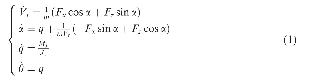
where

whereVtis the velocity;mis the mass;θ is the pitch angle;α is the angle of attack;qis the pitch rate;¯cis the mean aerodynamic chord;Srefis the reference wing surface area;Jyis the moment inertia along aircraftYaxis;gis the acceleration of gravity;is the dynamic pressure,ρ is the atmospheric density.The main structure parameters can be obtained by consulting full-scale model of NASA’s GTM16used in this paper and the detailed polynomial model parameters of axial force coefficientCx,normal force coefficientCzand pitching moment coefficientCmcan be found in paper,which are obtained from flight test;9they are polynomial functions of α,qand the elevator de flection δe.TxandTzare the thrust along aircraftXaxis andYaxis,respectively,which are the function of the thrust coefficient δth.
We consider a level flight condition, the speedVt=162.2885 m/s, and the altitudeH=4000 m,Vt0=162.2885 m/s, α0=5.0229°,q0=0(°)/s, θ0=5.0229°,δe=2.7269°,δth=0.35028.
The subscript‘0” represents a trim value.Note that the following analysis is on the basis of the condition.
As known to all,the scheduled control law applied to the designed aircraft is based on a PID controller.And the proportional-integral feedback controller as a simple class of PID controller is usually utilized to compensate for flight quality.So the PI controller for pitch attitude tracking is implemented in this paper to improve the flight quality and make a pitch attitude hold;dynamic envelope of an aircraft with PID controller can also be determined by this theory.The control law simulated in this paper is expressed below:

where Δα = α0- α are state errors;kα,kqandkθare the control coefficients for the state feedback controller;θrefis the pitch angle command derived from pilot command.kα=-8,kq=-2 andkθ=-6 are utilized in order to make the aircraft possess better flight quality in level flight,of which the θrefis equal to θ0.
4.Significant technology in EPS
4.1.Differential manifold theory
We consider a nonlinear autonomous dynamical system described by

wheref:Rn→Rnis continuous and sufficiently smooth,and satisfies Lipschitz condition inx.
There are two classes of Equilibrium Points(EP),Stable Equilibrium Point(SEP)and Unstable Equilibrium Point(UEP).The anterior one is an equilibrium point,at which every eigenvalue of the Jacobian matrix only possesses negative real part.And the latter one is an equilibrium point,at which eigenvalues of the Jacobian matrix possess positive real part.If the number of eigenvalues with positive real part is equal ton,the dimension of the system,the UEP is called a sink;if not so,the UEP is called a saddle.
As for a saddle expressed byxu,the stable manifoldWs(xu)and unstable manifoldWu(xu)exist,which can be defined as the following:

where φt(x)is called the flow induced by the vector fieldf,and also the trajectory.
Moreover,as for a SEP expressed byxs,stability region exists,which is denoted byA(xs),that is,the set of all points which the trajectory started from converges toxs.And the stability region can be expressed by,

And the boundary of the stability region is denoted by∂A(xs).Furthermore,the EP denoted byof ∂A(xs)is the UEP.Satisfy the conditions thatWu∩A(xsandWs∂A(xs),and it can be sure that the EP is at ∂A(xs).Based on the differential manifold theory,the boundary of stability region ∂A(xs)at a SEP is the union of the stable manifolds of the equilibrium points on the stability boundary;∂A(xs)can be expressed as follows:

wherexi(i=1,2,···)indicate the equilibrium points on the stability boundary.And the proof of this theorem can be seen in Ref.17.
Note that the aircraft can be regarded as a differential system which possesses many operating trim points,and the operating trim points are the same as the equilibrium points of a differential system.Furthermore,in order to meet the requirement of manipulation performance and stability,in the aircraft design,stable,accurate and rapid response to the input of a designed aircraft is demanded.Moreover,some inapposite properties,such as underdamping or undamped oscillation,must be avoided.So there is no eigenvalue with zero real part at an operating trim point for a designed aircraft.And the flight envelope determination for an aircraft via the differential manifold theory without taking closed orbit into account is also feasible and accurate.
4.2.Dynamic envelope
This section will represent the results based on the differential manifold theory.We consider the differential dynamic system expressed in Section 3.Because ofVtas a slow variable and the difficulty in visualizing the envelopes for a system,of which dimension is more than three,18the flight state of α,θ andqis selected for verifying the feasibility and accuracy when the flight velocityVtis equal toVt0,and of course,the method is still applicable to the situations with variousVt.So the result with constantVtunder the trim condition mentioned in Section 3 is as follows.
Fig.2 illustrates the global viewpoint of dynamic envelope based on the differential manifold theory.Furthermore,the result’s feasibility and accuracy are verified via comparing with the result of Monte Carlo method under the same condition,which can yield a real dynamic envelope by making numerous computations at certain space,and the comparing result is shown in Fig.3.As shown in Fig.3,envelope obtained by this paper’s method,which is drawn with the curve,is completely in conformity with that of Monte Carlo method,which is described with the surface,so we can make a conclusion that the method in the paper is accurate and feasible.
In order to account for the necessity of an envelope with taking multifactor into account,the slice for the envelope above under the condition of θ =5°,9°and 13°is taken as an example,which is described in Fig.4.In the figure,the coupling impact is obvious among α,θ andq.Specially,considering the curve with dot of θ =13°,the permissible angle of attack(10°whenq=5°/s),above which an envelope departing even LOC can occur,is much lower than the stall angle of attack(21°19).From the example above,we know that there is a possibility for an aircraft of flight state to depart the dynamic envelope and even to make an accident or incident due to the coupling effect between the flight states,although the aircraft does not encounter any upset condition.However,the conventional EPS with predetermined limits on some parameters to some extent cannot do with coupling effect well,which is discussed in detail via an example about an aircraft encountering gust in Section 5.Thus,in order to reduce the probability of flight accident,the envelope for an EPS must take multifactor into account.

Fig.2 Dynamic envelope with global viewpoint.
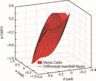
Fig.3 Comparison between two methods.

Fig.4 Slices of dynamic envelope with constant θ (5°,9°and 13°).
4.3.Envelope database establishment
LOC envelope is various along with the change of commands and control coefficients for a given control structure,which is designed to achieve premeditated functions,e.g.,pitch attitude hold and stability augmentation.And in order to guarantee safety for an aircraft under upset condition,it is necessary to understand the maximal controllable set of the control law utilized,which provides a crucial advice for whether it is required to change control law or pilot command or not.In view of the bad flight quality when the controllable set is maximal,the largest available envelope,which is determined under the condition of insuring the degree of flight quality to be no less than two,is utilized instead of the maximal controllable set.Hence,besides the envelope data with various control coefficients or pilot commands,there is the largest available envelope and corresponding control coefficient needed in the envelope database.In addition,the envelope data can be scheduled according to control coefficient or command or both.In view of the similar transformation of the envelope for various control laws,the results of an aircraft with the control law given in Section 3 with differentkθand θref,which are drawn in Figs.5 and 6,are taken as an example for illuminating the feasibility to prevent envelope departing via envelope enlargement.And on the basis,the database can be established via abundant simulation to various conditions.Fig.5 shows the envelopes for variouskθ,and compared with the referenced envelope,of which control law and its coefficients are selected from Section 3,the degree is diverse for envelope enlargement or shrinkage under differentkθ.Furthermore,the largest available envelope obtained askθ=-1 is illustrated in the figure,while,as shown in Fig.6,the referenced envelope moves along the change direction of command without any shape change to some extent.Moreover,because both location and bound are just altered together without inducing any other coupling effect after changing both coefficient and command,the condition will not be analyzed in detail.
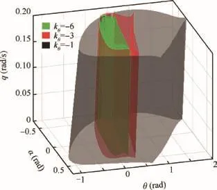
Fig.5 Envelope enlargement for various kθ.

Fig.6 Envelope translation for various θref.
4.4.Quantification of flight security
Considering that the closer flight state is to dynamic envelope,the bigger LOC risk is,the relative distance between flight state and dynamic envelope can be regarded as the quantification of risk as well as security.Hence,expression of safety factorSfused in the paper is represented as follows and its geometric definition is shown in Fig.7.

In Fig.7,pointSis the SEP,as well as a trim point or a target state,denoted byxs;pointFis the flight state denoted byxf;pointEdenoted byxeis the intersection of the dynamic envelope and the ray,which starts from pointSand passes through pointF.As shown in the figure,we know thatSf∈(0,1)indicates safe flight(Condition 1 in Fig.1),of which the flight state is inside the envelope,whileSf∈(-∞,0)indicates risky flight(Condition 2 in Fig.1),of which the flight state is outside the envelope;Sf=0 indicates critical safety.Furthermore,safety margin is improved via premeditating the lower limitrather than 0 forSf,just like the engineering method to enhance flight safety,e.g.,available angle of attack as a limit,which is smaller than stall angle of attack,is utilized in EPS to predict stall.Hence,Sfis feasible to be proposed for estimating whether there is a possibility to induce LOC or not.Furthermore,asSfis proposed,there are also some effects for preventing the envelope shrinking induced by imprecise dynamic model.
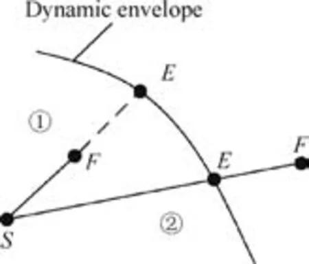
Fig.7 Geometric definition of safety factor.
In view of data point in Cartesian coordinate as a form for dynamic envelope storage rather than a continuous function,pointEwould be calculated by numerical computation instead of analytic method.So the computed expression used in the paper is represented as follows:

where

andnis the number of points in the dynamic envelope.
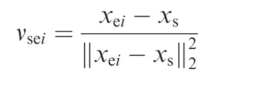
Subscript ‘i’is used to distinguish various points in the boundary.
4.5.Control coefficient determination
Considering that there is a limit determined of fline for envelope enlarging via changing control coefficient rather than configuration,the time for flight state departing to the largest available envelope stored in the envelope database can be used to represent the serious degree of danger.Due to the difficulty in getting the theoretic time in flight,an estimating time indicated byis regarded as a replacement,which is expressed as follows:

whereis the derivative of safety factor,is the safety factor for the largest available envelope whenSf=,andis the limit of safety factor.
To make the definition proposed above much clearer,a figure for the geometric definition of them is drawn in Fig.8,in which the calculated method is also provided viaSfcurve.In addition,the limit of safety factoris equal to 0,and conclusions when the limit of safety factoris not equal to 0,which are not given in this paper,can be obtained easily according to this.From the physics meaning of the Eq.(11),we know the geometric definition foris the time of the intersection between tangent forSf=0 and straight line forSf=-And the time,whenSffor the largest available envelope is equal to 0,is the theoretic time indicated byfor flight state departing to the largest available envelope.

Fig.8 Geometric definition in Sfcurves.
Moreover,guaranteeing safety for the aircraft with an EPS applying the envelope enlargement theory,the enlarging speed for an envelope must be more than that of envelope departing,of which the meaning is the same as that oftee≤,whereteeis the time constant of envelope enlarging from original one to the largest available one.Soknew,one of the new control coefficients such askθexpressed in Eq.(3),as well as the other coefficients in various control configurations,can be obtained by the following expression:
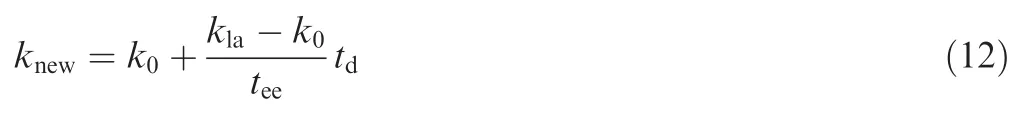
wherek0is the control coefficient for the normal flight condition;klais the control coefficient for the largest available envelope;tdis the time after the first time to detect the warning signal of envelope departing,of which geometric definition can be seen in Fig.8.
According to Eq.(12),we know that the core for the control law is to calculatetee,the time constant of envelope enlarging from original one to the largest available one,which has a direct relation with.Andcan be obtained based on theSfcurve.Furthermore,considering that it is the condition oftee≤that guarantees the flight state under upset condition inside the enlarged envelope,the departing speed is mitigated unless the external disturbance which is applied to the system is strengthened.Hence,it is not necessary forteeto change along withtdall the time.In view of this,teeis not updated until the warning signal of envelope departing is detected once again.The detailed approach of the control law determination is as follows:
Step 1.DeterminewhenSf=Sf.
Step 2.Calculateby utilizing information of theSfcurve.
Step 3.Estimateon the basis oftee≤and the limit of change speed for the aircraft sensor parameters.
Step 4.Judge whetherSfexceeds its limit once again.If so,repeat from Step 1 to Step 3 to recalculatetee,or keepteeestimated in Step 3.
5.Envelope protection under hazard gust wind
In this section,dynamic characteristics for an aircraft with the controller in Section 320and the EPS proposed in this paper are taken as an example under the flight condition of encountering hazard gust wind during the time when the pilot changes pitching command θreffrom θ0to 0.233.The example is equivalent to simulating a condition from level flight to the climbing phase encountering hazard gust wind.The level flight condition and the corresponding control law utilized are listed in Section 3.In addition,the wind gust21applied to the system,which possesses vertical speedVup,is shown in Fig.9.And dynamic characteristics with conventional EPS and its safety factor are illustrated as follows.
As shown in Fig.10,although the maximal angle of attack is about 15°,which is lower than the stall angle of attack(21°)and need not to be restricted by the traditional angle of attack protection system,LOC still occurs due to the coupling effect among angle of attack,pitch angle and pitch rate just like the illustration for Fig.4.However,Fig.11 shows the advantage ofSfto detect premonition of LOC.According to the geometric definition of safety factor and the envelope utilized in the paper,LOC occurs at about 1.3 s,of whichSf≈0,and finally an accident is induced without anything done.Hence,it is feasible to appendSfto EPS as a warning signal for detecting LOC,which also includes the stall.The simulation under the same condition with the EPS proposed in the paper is as follows.

Fig.9 Wind gust with 15 m/s maximum amplitude.
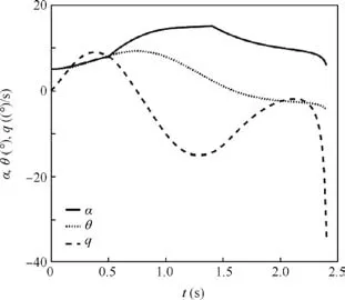
Fig.10 Dynamic curves with conventional EPS.

Fig.11 Sfcurve with conventional EPS.
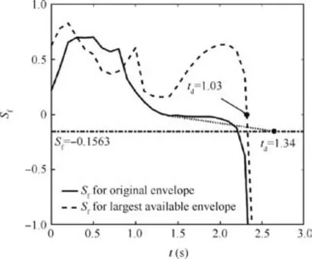
Fig.12 Geometric definition forand.
When the warning signal for envelope departing is detected,which means that there is a risk to make LOC occur,the control coefficients are determined by the EPS according to.In this example,=1.34 calculated from Eq.(11),where=0.117 and=0.1563.In order to provide a better explanation,Sfcurves for both original envelope and the largest available envelope are drawn in Fig.12.As shown in the figure,the geometric definition foris the time of the intersection between tangentforSf=0and straightlineforSf=-.And the time,whenSffor the largest available envelope is equal to 0,is the theoretic time indicated byfor flight state departing to the largest available envelope,which is equal to 1.03 in this example.And considering that theoretic timecannot be obtained before envelope departing,an estimating timeis selected.
By meeting the requirement oftee≤,we maketee=1.And the control coefficient for envelope enlargement is expressed as follows:


Fig.13 Dynamic curves with EPS proposed.

Fig.14 Dynamic curves without encountering wind.

Fig.15 Sfcurves with EPS proposed.
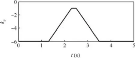
Fig.16 Control coefficient change in flight.
The dynamic characteristics for an aircraft with EPS proposed are illustrated in Fig.13.And the behavior with the conventional EPS under the same condition without encountering gust wind is shown in Fig.14.As shown in these figures,the final flight state is trend to the expectant situation in security,which indicates that the EPS is feasible based on the theory proposed in the paper.In addition,the corresponding safety factor during five seconds is illustrated in Fig.15 and the control coefficient for the condition in flight is drawn in Fig.16.As shown in these figures and in view of the above analysis,considering whent=1.3 s,of whichSfis a little more than 0,there is a risk for the aircraft in LOC due to detection of the warning signal for envelope departing.At the same time,in order to guarantee safety,the law of coefficient change is obtained via a series of analysis for security by EPS.Due to the change of the envelope derived from database with variouskθ,in flightSftransfers between the original one and the largest available one.In the curve for in flightSf,it is sure that the flight state recovers to the original envelope becauseSffor original envelope is more than 0 whent=1.8 s.For the quick performance of achieving flight task,control coefficient also needs to be recovered.In view of this as well as flight security,the coefficient curve is shown in Fig.16.
6.Conclusions
The envelope protection system based on the dynamic envelope enlargement is proposed in this paper,which can guarantee safety of an aircraft encountering upset condition.And the feasibility of the system is verified via taking an example of NASA’s Generic Transport Model encountering hazard gust wind to occur LOC due to the coupling impact among flight states,e.g.,pitch angle,angle of attack and pitch rate,which cannot be protected by conventional EPS of angle of attack.More results obtained in this paper are as follows:
(1)Dynamic envelope based on the differential manifold theory is consistent with the real dynamic envelope and has the characteristics that the sharp can be enlarged via changing the control coefficients and the location can be translated with the change of pilot commands.
(2)Dynamic envelope based ROA method has direct relation with the pilot command and the control parameters,so it is very useful to ensure aircraft safety and provide advice for operation of an aircraft encountering upset condition.
(3)Relative distance between flight state and dynamic envelope can be used as a quantification of flight security to quickly detect the signal of whether there is a risk for an aircraft encountering upset condition.
Acknowledgement
This study was supported by the National Key Basic Research Program of China(No.2015CB755805).
杂志排行
CHINESE JOURNAL OF AERONAUTICS的其它文章
- Particle image velocimetry for combustion measurements:Applications and developments
- Abnormal changes of dynamic derivatives at low reduced frequencies
- A new hybrid aerodynamic optimization framework based on differential evolution and invasive weed optimization
- Experimental study of an anti-icing method over an airfoil based on pulsed dielectric barrier discharge plasma
- Effects of the radial blade loading distribution and B parameter on the type of flow instability in a low-speed axial compressor
- Adaptive sliding mode control for limit protection of aircraft engines