Dynamic modeling of spacecraft solar panels deployment with Lie group variational integrator
2018-02-13LongBaiXinshengGe
Long Bai*, Xinsheng Ge
School of Mechanical and Electrical Engineering, Beijing Information Science and Technology University, Beijing 100192, China
Keywords:Lie group Variational integrator Spacecraft Solar panels deployment Dynamics modeling
A B S T R A C T The spacecraft with multistage solar panels have nonlinear coupling between attitudes of central body and solar panels, especially the rotation of central body is considered in space. The dynamics model is based for dynamics analysis and control, and the multistage solar panels means the dynamics modeling will be very complex. In this research, the Lie group variational integrator method is introduced, and the dynamics model of spacecraft with solar panels that connects together by flexible joints is built. The most obvious character of this method is that the attitudes of central body and solar panels are all described by three-dimensional attitude matrix. The dynamics models of spacecraft with one and three solar panels are established and simulated. The study shows Lie group variational integrator method avoids parameters coupling and effectively reduces difficulty of modeling. The obtained continuous dynamics model based on Lie group is a set of ordinary differential equations and equivalent with traditional dynamics model that offers a basis for the geometry control.
Space technology of China is fast developing in recent years.The advanced technology and task diversification bring new needs and challenges to the exploration of basic theory of dynamics and control of spacecraft. The spacecraft consists by a central rigid-body platform and multi-stage solar panels, which are connected together by flexible joints. So there is a coupling relation between solar panel deploy and attitudes maneuver.The multistage solar panels make this problem more obvious,which brings certain difficulties to the dynamic modeling of the whole system. So a new modeling method that can avoid this coupling relation should be explored.
The computational geometry mechanics provides new ideas for complex system dynamic modeling. Differential geometry is a mathematical tool that explores the spatial geometric properties. The research objectives evolve from curves and surfaces in three-dimensional space to more general spatial manifold problems such as Riemannian manifolds and Lie groups. Combine with Lagrange mechanics, Hamiltonian mechanics, differential geometry, nonlinear programming and optimal control theory,the geometry mechanics offers a new domain for multi-body system dynamics such as spacecraft systems which has important theoretical value and significance.
The difference between classical method and geometry method is the long time conservation character. The classical method can't maintain conservation of energy, momentum and structure when the dynamic system is discrete, which leads to the loss of energy or momentum in long time simulation.However, geometric method can avoid the problems which occurred in classical method because it can maintain conservation of the above physical quantities, which improves the accuracy of calculation during long time simulation. The efficiency and convergence of optimal control can also be enhanced.
A great deal of works has been done on geometric mechanics. Leok [1] elaborated geometric mechanics in his doctoral thesis, and based on Leok's research, Lee [2] studied the dynamic problems of different types of rigid body systems with Lie group variational integrator method and he also explored the optimal control problems of multi-body systems with discrete Lie group variational integrator method. In addition, in the subsequent research, geometric mechanics-based methods have been used in the domain of spacecraft formation stability [3],spacecraft docking control [4], spacecraft attitude control with momentum wheels [5], and autonomous spacecraft rendezvous and docking. The problems of mode control [6] is studied by geometry method, Nordkvist and Sanyal [7] applied the Lie group variational integrator to underwater robot dynamics. It means the application range of geometric mechanics has been developed not only in rigid body systems, but also to flexible systems and fluid systems. In the framework of geometric mechanics, Samiei et al. [8] studied continuous nonlinear delay feedback control problem to stabilizes rigid body attitudes. Xiang et al. [9] studied collocation method on Lie group and applied it to the solution of rigid body optimal control. In this study, the Gaussian pseudo-spectral method and Lie group variational integrator are combined together, which offers higher precision,time performance and structure conservation characters. Hall and Leok [10] used the Galerkin variational integration method to establish a numerical integration method that preserves geometry and symplectic-momentum conservation. Hassing [11]solved control problem of planar robots with non-holonomic constraints, the dissipative and geometric manifolds represented using geometric mechanics.
In the field of spacecraft attitude dynamics and control, Ge et al. [12–15] have carried out a series of studies on the deployment dynamics and control of spacecraft solar panels. The dynamic model of spacecraft solar panel deployment is established,which provides the basis for the subsequent motion planning and optimal control problems.
In this paper, the dynamic model of the spacecraft during the solar panels deployment is derived out with the Lie group variational integrator method, and the rigid and flexible coupling dynamics model of spacecraft with one and three solar panels which considering joints flexibility are established and simulated. The study shows that the Lie group variational integrator method effectively reduces the difficulty of modeling.
Before introduce the Lie group variational integrator, the Lagrange theory should be summarized as follows. Define the generalized coordinate and velocitiesthe Lagrange function of system is as Eq. (1)

The dynamic equation of system is derived by Eq. (2)

According to Legendre transformation, the Lagrange equation can be converted into a Hamiltonian form with generalized coordinates and generalized momentum as independent variables, which is defined as Eq. (3)

The Hamilton dynamics equation is obtained by Eq. (4)

The dynamic modeling method based on Lie group variational integrator is described as follows. The rotation matrixis used to represent the rotation of body coordinate system relative to inertial coordinate system.is a vector from rotation center to rigid body center in body coordinate system. Potential energyis only related to the attitude of rigid body.is a vector from rotation center to a certain mass element in body system;is angular velocity of rigid body in body system. Then the speed of mass element is. The Lagrange function of the spatial three-dimensional (3D) rotating rigid body can be expressed as Eq. (5)


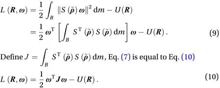
Equations (8) and (10) are two equivalent but different forms function.is standard moment of inertia matrix,is nonstandard moment of inertia matrix. The exchange relationship betweenandis as Eq. (11)

The relationship of angular momentumandcan be written as Eq. (12)

According to Eq. (8), define the integral as Eq. (13)

In Eq. (13), the drive force is not considered. It is a conservative system which has no energy exchange with surrounding. So the value of integralis 0. Definewith a small change is, so the relationship betweenandis expressed as Eq. (14)


Substituting Eqs. (6) and (16) into Eq. (17), the skew of the angular velocity can be written as Eq. (18)

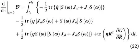
The variation of Eq. (13) can be expressed as Eq. (19)


Substituting Eqs. (20) and (21) into Eq. (19) can obtain the result as Eq. (22)


Substituting Eq. (24) into Eq. (23) can obtain the result as Eq. (25)

In order to make Eq. (25) equals 0, the part which multiply with it should be a symmetry matrix, which means. Make the transformationthe result can obtain as Eq. (26)


Equation (27) is the dynamics equation,represents the torque which create by the potential energy. Definethe angular momentum, then the Hamilton type of Eq. (27) can be written as Eq. (28)


Substituting Eq. (12) into Eq. (29) can obtain the result as Eq. (30)


The result of Eq. (32) is as Eq. (33)

The above is the dynamic modeling process of Lie group variational integrator in dealing with three- dimensional spatial rotational motion. In the entire process, the use of trigonometric functions is avoided, and the workload of derivation is greatly reduced.
Figure 1 shows structure of a spacecraft with solar panels in plane. The center rigid body rotates around the center of mass, and solar panels rotate along their rotation centers. To establish overall dynamics model, the motion parameters of each rigid body should be obtained. Assuming the inertial coordinate system coincidence with, the position vector ofcan express as Eq. (34)

The end position vector of the first stage solar panel can be written as Eq. (35)

The position of mass center of central body is Eq. (36)

The mass center of first stage solar panel is as Eq. (37)

So the potential energy of whole system is as Eq. (38)

The kinetic energy of the central body is Eq. (39)

The kinetic energy of the first stage solar panel includes the moving energy and energy of rotation that can be written as Eq. (40)
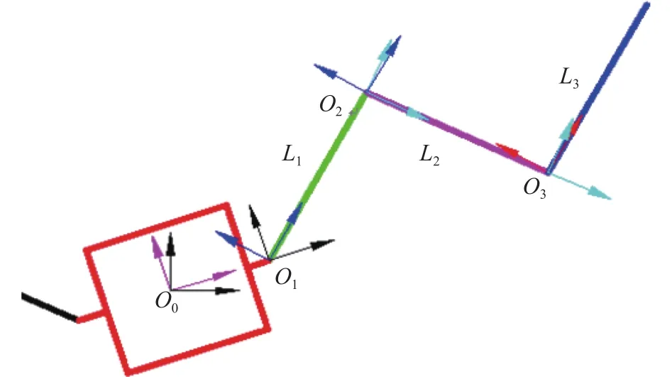
Fig. 1. Structure of spacecraft with solar panels on surface.


The rotation matrix of first stage solar panel is, the angular velocity of it can be written as Eq. (42)

According to upon two equations, the kinetic energy of first stage solar panel is as Eq. (43)

When central body and solar panel are rotating in same plane, they both are two-dimensional matrixes that has a triangle function expression as Eq. (44). The skew symmetry matrix has characters as Eqs. (45) and (46)

Upon this condition, the kinetic energy of first stage solar panel is simplified as Eq. (47)

In a similar way, the kinetic energy of central body can be simplified as Eq. (48)

The potential energy of whole system is as Eq. (49)

So Lagrange function of system is written as Eq. (50)


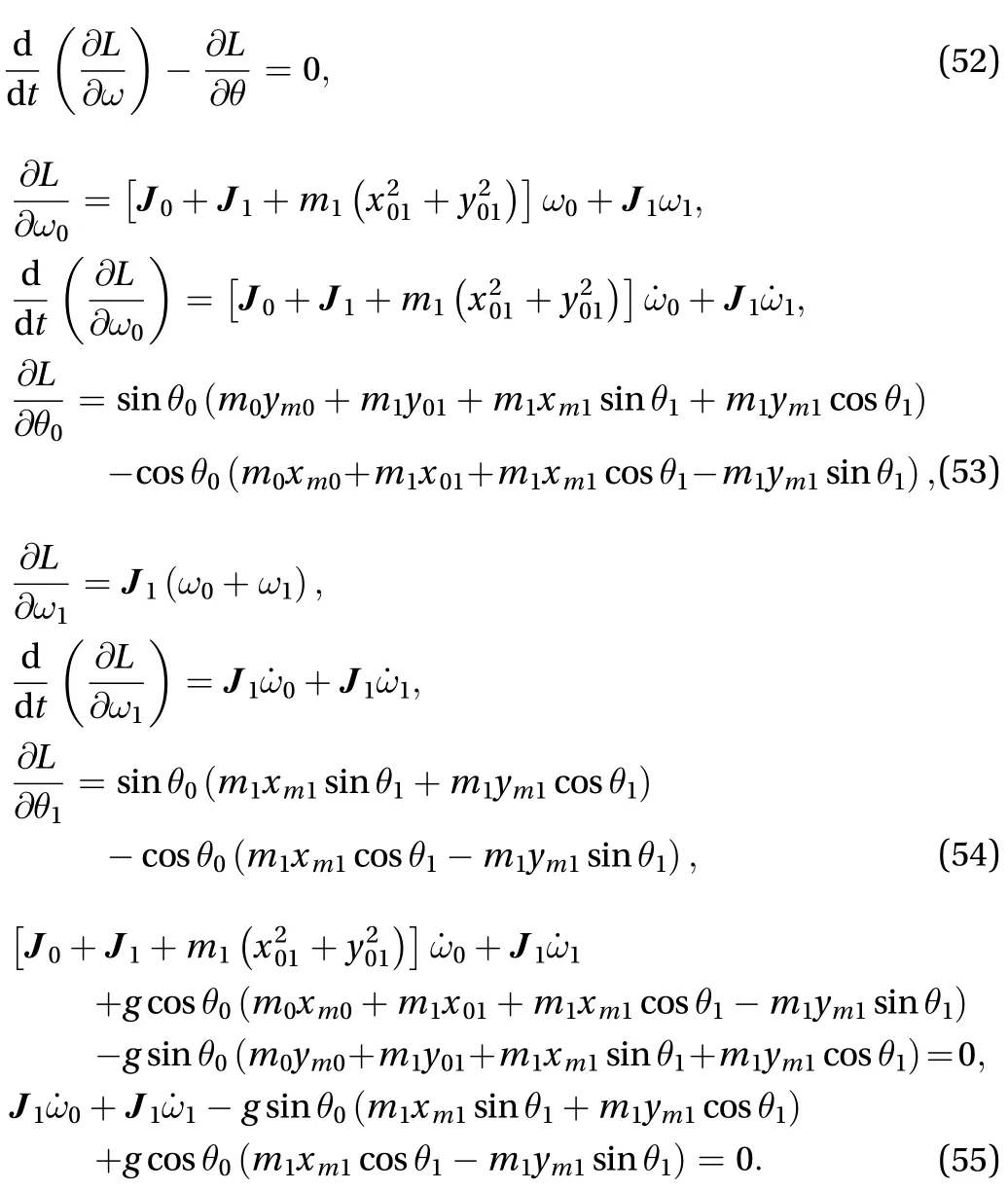
According to Eq. (52), the dynamics equation can be derived out and get the result as Eq. (55)
The dynamics modeling for the spacecraft with solar panels by Lie group variational integrator method is summarized as Eq. (56)

The expressions of each part in Eq. (56) are as Eq. (57) to Eq. (59)
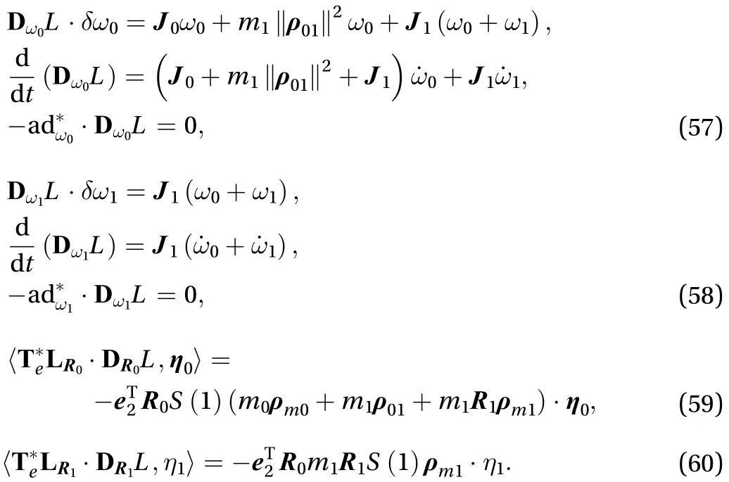
According to Eq. (58) to Eq. (60), the dynamics equation of the system is as Eq. (61)

Through above derivation process, it can be seen that spacecraft dynamics model derived from Lie group variational method is equal to the traditional type. The Lie group method uses rotation matrix as the calculation unit. The complexity of derivation is greatly reduced.
The kinetic model of spacecraft with three stage solar panels is derived below. The motion of spacecraft with one solar panel is shown in Fig. 2, the rotation of following solar panels are identical to the first. Define inertial systemand body system, which are coincide together in initial. The origins of these two frames are coincides too. The rotation of central body is expressed bywhich represent the attitude ofrelative to. The body coordinate of solar panel iswhich rotate relative to, and the corresponding attitude matrix is. The center rigid body has three degrees of freedom that meansso the corresponding three-axis angular velocity is.

The rotation of the first solar panel is a single freedom rotation. As shown in the figure, the rotation around thex-axis, so the corresponding attitude matrix is, set the rotation angle is, then the concrete expression ofis as Eq. (61). Differentiate rotation matrixcan get result as Eq. (62)

Base on Lie group variational integrator method, the dynamics equation of spacecraft with three-stage solar panel in space is derived below. The attitude matrices of the central rigid body and solar panels arerespectively, the position ofin their respective body systems are. The mass center position vectors of central body and solar panels arerespectively. After the central body rotates a certain angels around, the positions of each joint of solar panel is Eq. (63)
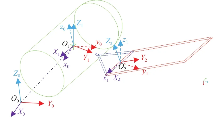
Fig. 2. Spacecraft with solar panels in space.

The positions of each mass center is as Eq. (64)

So the potential energy of the whole system is as Eq. (65)

The elastic energy on each joint is as Eq. (66)

The overall kinetic energy of system includes the rotation kinetic of central body, the rotation and moving kinetic of solar panels which is as Eq. (67)

The center rigid body's kinetic energy is as Eq. (68)

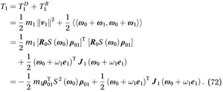
The kinetic energy of first solar panel includes spatial moving energy of center point of rotation and kinetic energy of rotation around the center of rotation which is expressed as Eq. (69)


The rotation of the first solar panel in inertial system is the coupling of central body rotation and its own rotation, so its rotation matrix is, and its corresponding angular velocity is Eq. (71)


The rotation matrix of the secondary solar panel in space isand its corresponding angular velocity is as Eq. (74)

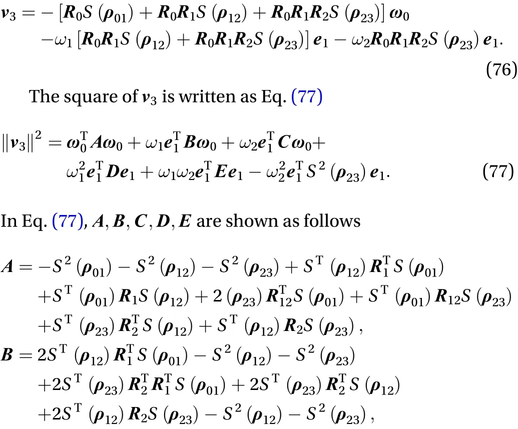
According to the position of the third-level solar panel hinge in space, the speed of the thirdlevel solar panel hinge in space is as Eq. (76)

The rotation matrix of the third solar panel is, and its corresponding angular velocity is as Eq. (78)

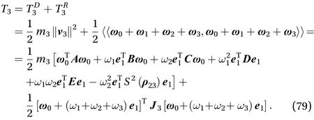
Then the kinetic energy is as Eq. (79)
The Lagrange function of the derived system based on the above derivation is as Eq. (80)

The main parameters are as follows
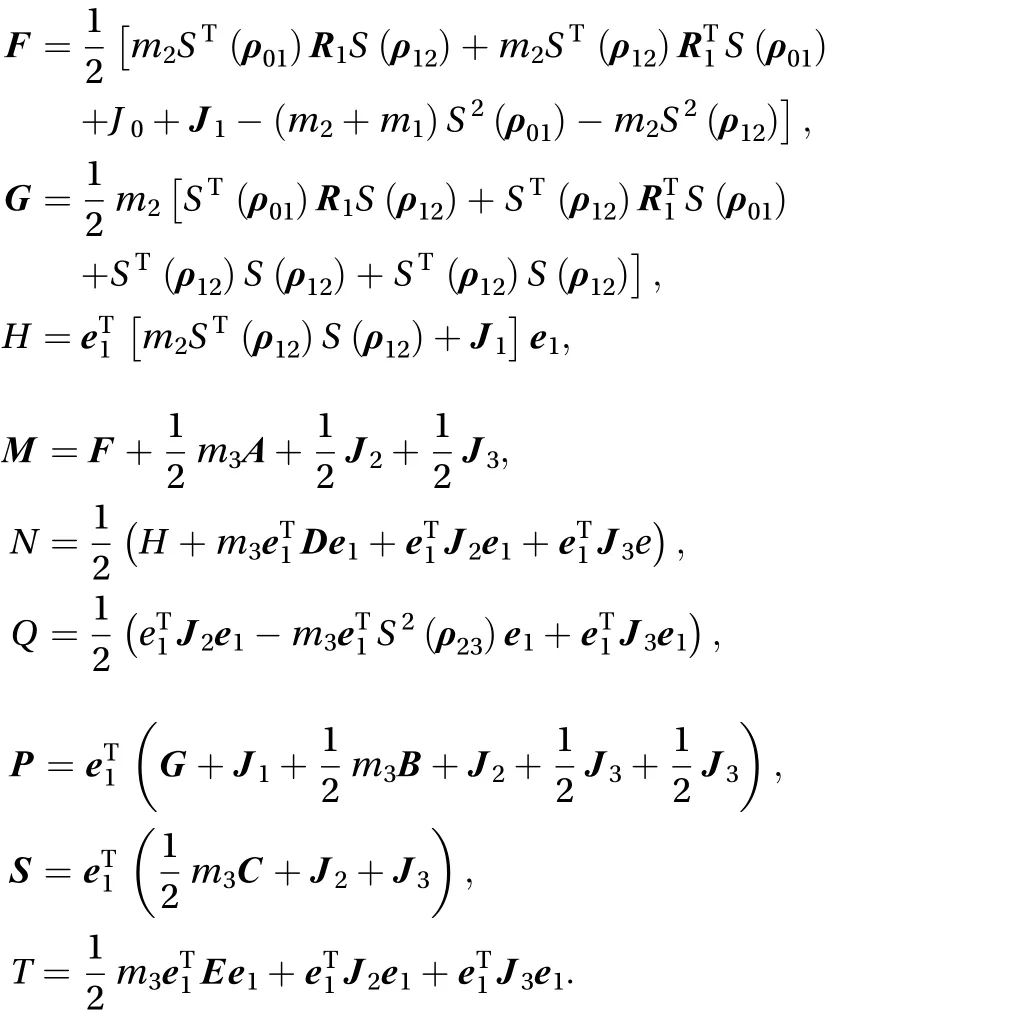
The dynamics equation of the system is derived below
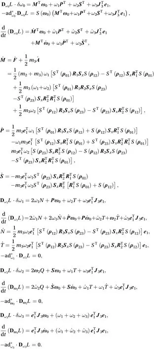
The following parts can be obtained after the variation of the attitude matrix

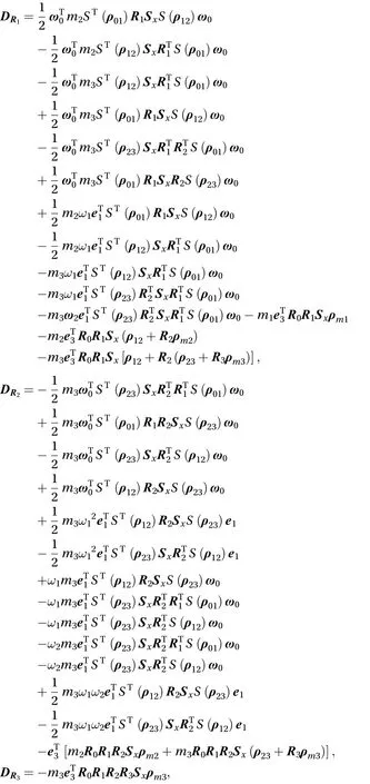
According to the about analysis and Eq. (56), the dynamics equation can be written as follows
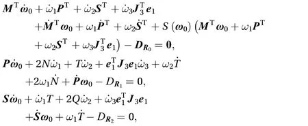

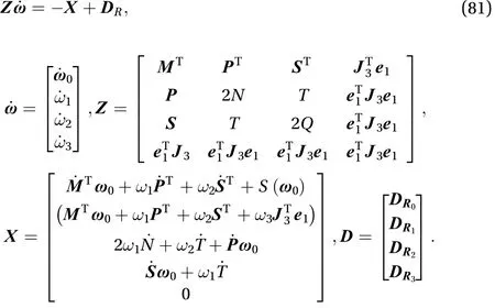
The dynamics equation of the system can be written as a neatly type as Eq. (81)
When the spring torque on each joint is considered, the dynamic equation of the system is expressed as Eq. (83) which the spring force is added into the equation

In order to verify the correctness of the above derivation,MATLAB is used to simulate the results. Firstly, the dynamics model of spacecraft with one solar panel in plane is verified. The main structure parameters are as follows. The mass of the center rigid body is, the position vector of the mass center of the central rigid body to the rotation center is2, the moment of inertia of the center rigid body is=100 kg·m, the mass of the solar panel is, and the installation position of the solar panel on the center rigid body is. The moment o2f inertia of the solar panel around the rotating axis is=10 kg·m, the position vector of the center of mass of the solar panel is, the spring stiffness coefficient of the solar panel and the center rigid hinge is=100 N·m·rad–1, the initial posture and angular velocity of the central rigid body and the solar sail areand, respectively. Based on above data, the simulation results of the system are shown in the figure.
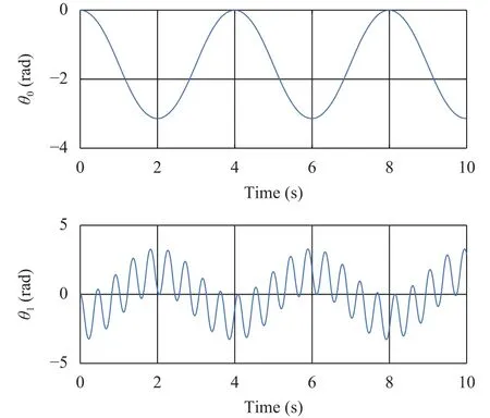
Fig. 3. Variation of rotation angles of center body and the solar panel.
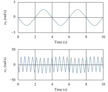
Fig. 4. Variation of angular velocities of center body and the solar panel.
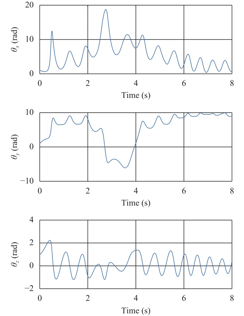
Fig. 5. Rotation angle variation of the central body.
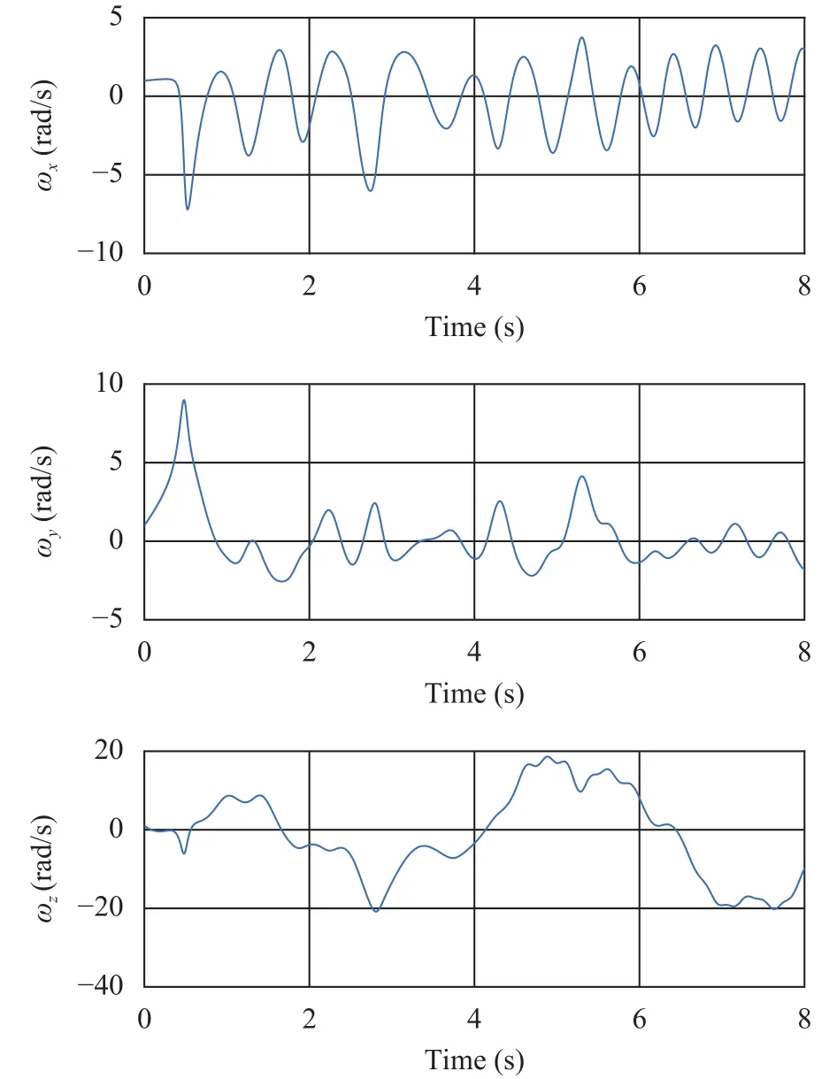
Fig. 6. Angular velocity variation of the solar panels.
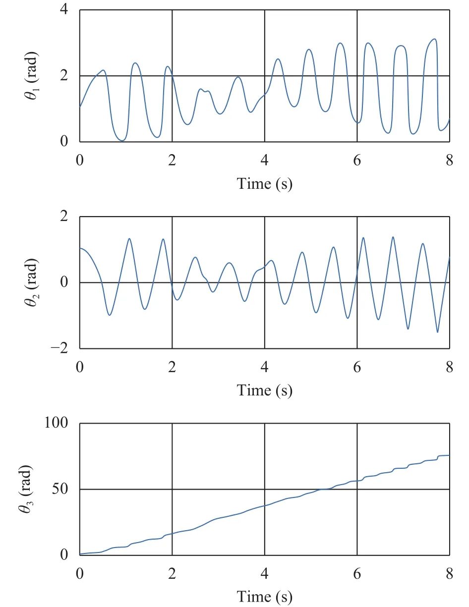
Fig. 7. Rotation angle variation of the central body.
Figures 3 and 4 are the variations of rotation angles and angular velocities of central body and solar panel in plane. From Fig. 3, it can be seen that the rotation angels of central body and solar panel show periodic changes, and the solar panel shows certain amplitude fluctuations under the influence of joint flexibility. Figure 4 shows the variations in angular velocity. It can be seen that the angular velocity of central body and solar panel show periodic character. Under the influence of flexible joints,the angular velocity fluctuation frequency of the solar panel is larger.
The dynamics model of the spacecraft with three-stage solar panels in space is calculated below. The mass of the center rigid body is 50 kg, the moment of inertia of each axis of the center rigid body is 10 kg·m2, and mass center position vector to the rotation center is [0; 1; 0]. The position vectors of the installation position of the solar panels are [0; 3; 0]. The three-axis inertia of solar panel is 5 kg·m2, 100 kg·m2, and 0.5 kg·m2, respectively, and the mass is 10 kg. The position vectors of the center of mass of the solar panel to the center of rotation are [0; 1.5; 0]. From the above data, the simulation results are shown in Figs. 7 and 8.
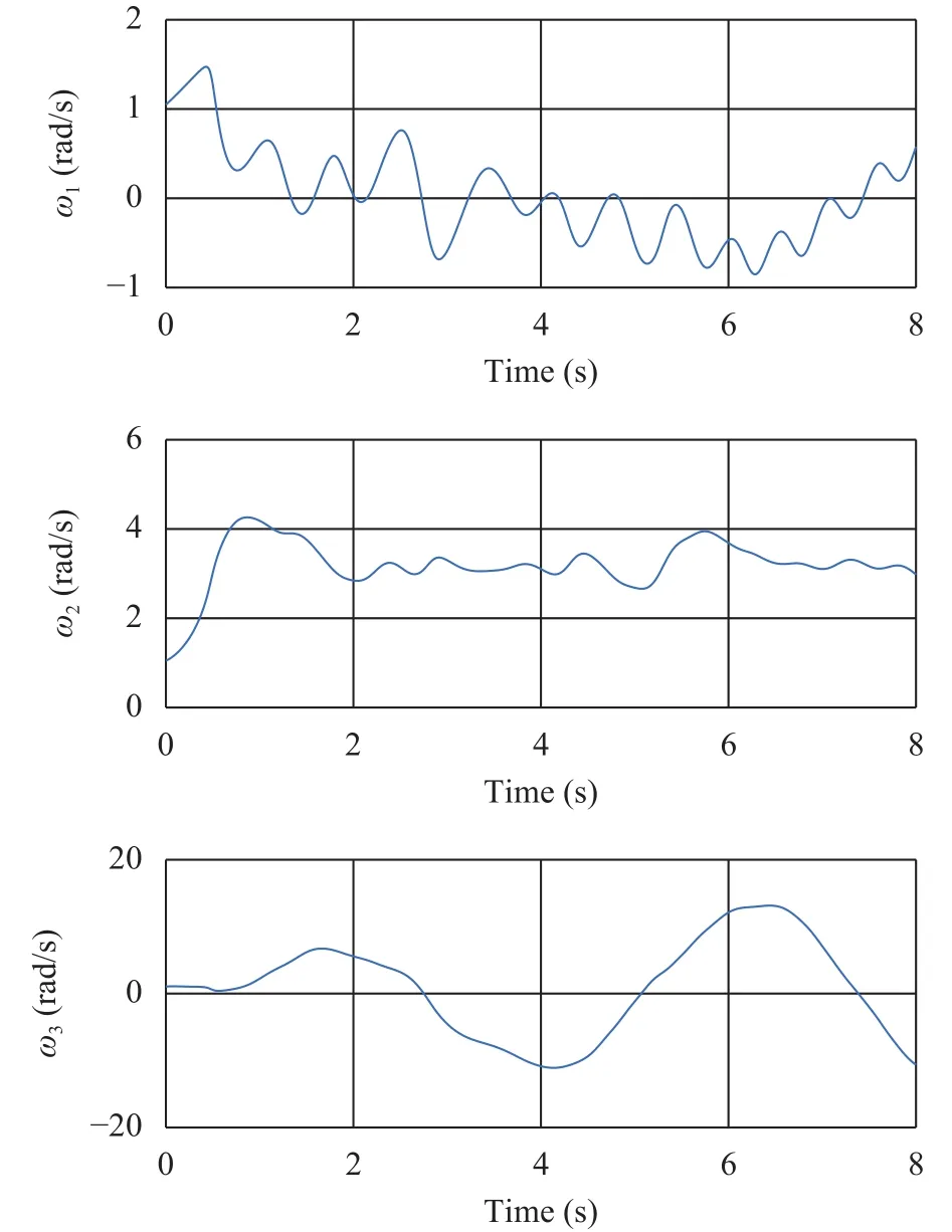
Fig. 8. Angular velocities variation of solar panels.
Figures 5–8 are the dynamics simulation results of spacecraft.It can be seen that under the action of solar panels, the overall dynamics of spacecraft changes. There is a significant difference between the dynamic characteristics of the model in plane and in space.
In this study, a complete dynamic model of a spacecraft with three-stage solar panels is established by using Lie group variational integrator method. It can effectively solve the problem of the coupling between the central body and solar panels at all levels. The derived dynamic model proves its correctness through simulation. The research provides foundation for the control of spacecraft with multistage solar panels and the study of Lie group discrete variational integrator.
Acknowledgments
The authors are grateful for the financial support from the National Natural Science Foundation of China (Grants 11732005 and 11472058).
杂志排行
Theoretical & Applied Mechanics Letters的其它文章
- Data-driven computing in elasticity via kernel regression
- The effects of mean sea level rise and strengthened winds on extreme sea levels in the Baltic Sea
- New interpretation of specific sign of Reynolds stress in the boundary layer on a flat plate
- An improved smoke-wire flow visualization technique using capacitor as power source
- Head-on collision between two hydroelastic solitary waves with Plotnikov-Toland's plate model
- Linear, nonlinear dynamics, and sensitivity analysis of a vibratory ring gyroscope
