Linear, nonlinear dynamics, and sensitivity analysis of a vibratory ring gyroscope
2018-02-13DongDongLingXioDongYngWeiZhngYunRenTinzhiYng
Dong-Dong Ling, Xio-Dong Yng,*, Wei Zhng, Yun Ren, Tinzhi Yng
a Beijing Key Laboratory of Non-linear Vibrations and Strength of Mechanical Engineering, College of Mechanical Engineering, Beijing University of Technology, Beijing100124, China
b Aerospace Engineering University, Beijing 101416, China
c Department of Mechanics, Tianjin University, Tianjin 300072, China
Keywords:Vibratory ring gyroscope Amplitude responses Nonlinear effect Sensitivity
A B S T R A C T The linear and nonlinear dynamic responses of a vibratory ring gyroscope are investigated in this study focusing on the response mechanism of such a vibratory gyroscope. It is found that the nonlinear equations governing the drive and sense directions are coupled through both inertial linear and geometric nonlinear terms. Nonlinear responses are studied based on the full coupled nonlinear dynamic equations. The varying amplitude on the sense direction is analyzed for different input angular rates. The effect of nonlinearity on the ring gyroscope system is performed by comparing the results of nonlinear responses to those of linear responses. The contributions of some parameters to the amplitude responses and gyroscope sensitivity are analyzed, the conclusions of which provide guidelines to improve the sensitivity of the vibratory ring gyroscopes.©2018 The Authors. Published by Elsevier Ltd on behalf of The Chinese Society of Theoretical and Applied Mechanics. This is an open access article under the CC BY-NC-ND license(http://creativecommons.org/licenses/by-nc-nd/4.0/).
Micro-vibration gyroscopes are one of the emerging inertial sensors [1-3] in recent decades, which are used to measure angular rate. The vibratory gyroscopes which apply vibrating structures to provide gyroscopic torque from Coriolis acceleration have received noticeable attention, due to the potential applications in the MEMS technology. In the family of vibratory gyroscopes, elements such as beams [4, 5], tuning forks [6, 7], springmass [8], and thin rings have been employed to play as the vibratory structural element. These gyroscopes share the same principle: when an actuation force is applied in one direction(drive direction), and if the angular velocity is applied externally,the vibration occurs in the other direction (sense direction) due to the Coriolis force.
Vibratory ring gyroscopes have been widely used because of the inherent advantages such as small size, high sensitivity to rotation, less sensitivity to environment vibrations, and good stability [9]. Therefore, vibratory gyroscopes play a key role in the navigation in a wide range of applications [10-12].
The early vibratory ring gyroscope was designed and researched in the last decade of the 20thcentury [9]. Since then, the vibratory ring gyroscopes have attracted more attentions.Evensen [13] analyzed the nonlinear bending vibration of thin rings by focusing on two vibration modes. Bickford and Reddy[14] analyzed the general problem of in-plane vibration of a rotating ring, taking into account the effects of shear deformation and rotational inertia. Huang and Soedel [15] studied the free and forced in-plane vibrations of a rotating ring resting on the foundation. The natural frequencies and modes of the telescopic and non-elastic conditions are analyzed and compared. Natsiavas [16, 17] studied the global dynamics of free nonlinear vibration of a thin rotating ring and the nonlinear dynamic response of a ring with variable rotational speed. Eley et al. [18]presented a study on the effects of coupling between the inplane and out-of-plane motions. Asokanthan and Cho [19-21]studied the dynamic stability of a ring type sensor whose angular rate may be disturbed by harmonics, when the ring system is subject to external excitation and its own rotation. Yoon et al.[22] analyzed the sensitivity of a vibratory ring gyroscope model.Nitzan et al. [23] and Polunin and Shaw [24] studied the self-induced parameter amplification of micromechanical resonant disk/ring gyroscopes. It has been verified that the parameter amplification can improve the sensitivity of the gyroscope. Cetin and Yaralioglu [25] presented the analysis of coupling between drive and sense systems of vibratory gyroscope, focusing on the shift phenomenon. However, the relationship between amplitude and angular velocity for the full coupled form of the nonlinear equations is not clear in the study of vibratory ring gyroscopes. The nonlinear mechanism is still in demand to show the nonlinear contribution to the sensitivity of the vibratory gyroscopes.
In the present paper, the nonlinear mathematical formulation of the vibratory ring gyroscope is obtained, and then the responses are investigated focusing on contributions of some key parameters. In the linear case, response characteristics at different angular velocities are studied in detail, and the effect of damping on measuring angular velocity in gyroscopes is investigated. Further, the nonlinear response is obtained numerically and the effect of nonlinearity on coupled motions is explored by comparing nonlinear results with linear results.
The vibratory ring gyroscope is mainly composed of a vibrating ring, elastic supporting structure, drive electrodes, sense electrodes and control electrodes [10], and the ring is completely symmetric. During the working process, there are two flexural modes, one is drive mode, and the other is sense mode.When a drive voltage is applied in the drive direction and a certain angular velocityis applied in the plane of the ring, vibration occurs in the sense direction at an angle of 45° due to the presence of the Coriolis force. From the energy point of view,Coriolis force induces energy transfers between two vibration modes. Based on this principle, the angular velocity of rotation is measured by measuring the energy transfer caused by Coriolis force. Figure 1 shows a simplified diagram of the internal structure of a vibratory ring gyroscope [24].
The governing equations of such vibratory ring gyroscope system in the drive direction and sense direction can be obtained by Newton's second law and then the truncation technique [24]:
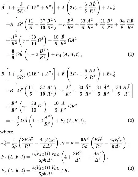
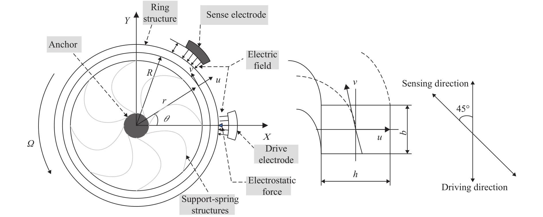
Fig. 1. Simplified model of internal structure of ring vibration gyroscope.
HereAandBare the generalized displacement coordinates of the drive direction and the sense direction for the first order mode,is the base natural frequency,is the effective nonlinear coefficient,is the intermodal coupling coefficient,is the external angular rate aboutz-axis,Ris the ring radius,his the ring radial thickness,is the vacuum permittivity,Eis young's modulus,is the density,△is the gap between the electrode and the ring,VDCandVACrepresent magnitudes of the bias and periodic voltages used for the electrostatic actuation and sensing,Aandare phenomenological dissipation coefficients for the drive and sense directions respectively.TermsFAandFBrepresent respectively the periodic excitation acting on the drive and sense modes.
Nonlinear equations of the vibratory ring gyroscope system[24] were established by considering the electrostatic effect between the ring and the electrode. It is clear that Eq. (1) on the drive mode is coupled by both gyroscopic term and nonlinear terms. The nonlinear terms include inertial ones (involving variables with over dot) and geometric ones (not involving variables with over dot). However, some studies have omitted electrostatic effect [15, 16, 20, 26], which leads to inaccurate nonlinear descriptions.
We use the full coupled equations to study the variation of amplitude with angular velocity. Firstly, the governing Eqs. (1)and (2) are rearranged as:

Introducing the following set of dimensionless variables and parameters

and substituting Eq. (7) into Eqs. (4) and (5), further removing the asterisk in the dimensionless variable, yield the following dimensionless equations
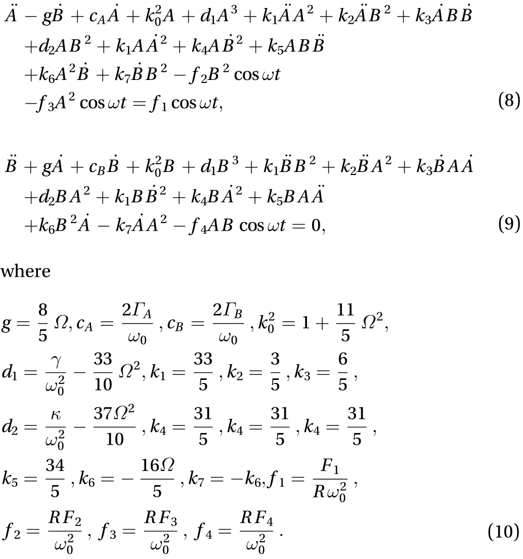
The values of parameters used in the paper are taken from Ref. [10] and listed in Table 1.
To investigate the response characteristics and sensitivity of the gyroscope in the linear case. Omitting nonlinear terms in the Eqs. (8) and (9), the following two linear gyroscopically coupled ordinary differential equations are recovered

For such typical damped gyroscopic equations, we focus on the impact of damping on the dynamics of the sense direction undergoing rotations.
Here the oscillation of the drive direction is considered to beharmonic. The particular solution to the Eq. (11) can be written as
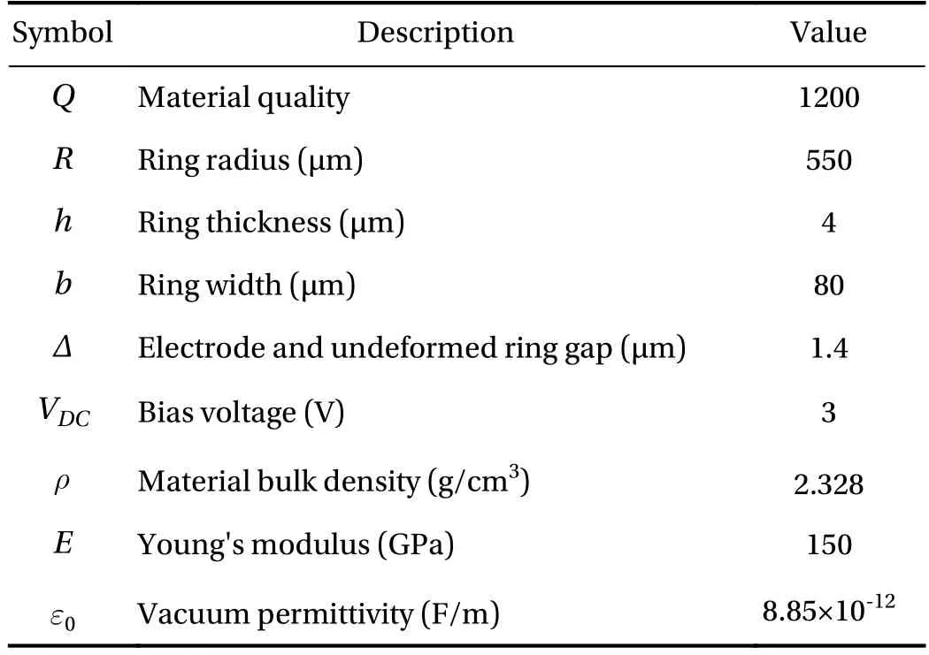
Table 1 Parameters of the ring vibrating ring gyroscope.

The forced system vibrates at the excitation frequency.However, the phase difference will remain for the drive direction and sense direction, due to gyroscopic coupling. Hence, the complex amplitudesC1andC2should be rewritten as

whereC10,C20,, andare the constant real amplitudes and phases of the drive direction and sense direction oscillations,respectively.
Substituting Eq. (12) into Eq. (11) yields the following system of algebraic equations in terms of complex amplitudesC1andC2
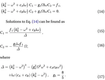
The complex amplitude method is used to analyze the amplitude and phase of the vibrating ring gyroscope system. By inspecting the complex values of Eqs. (15) and (16), we can find the phase differences among the sense direction, drive direction and the angular velocity. The real amplitudes and phases are obtained by converting the complex amplitudes Eqs. (15) and (16)as follows
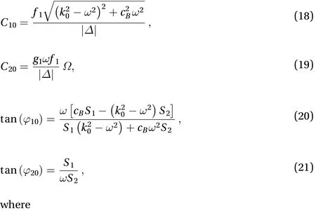

Similar investigations have been implemented in some paper [25, 27]. By studying the steady solution Eqs. (15) and (16), it can be concluded that without damping (cA,cB=0), the pure imaginary ratio between theC1andC2can be found, which indicate an exact/2 phase difference between the drive and sense direction. With the involvement of the damping, the phase difference is varying and the resulted dynamics becomes complicated to investigate.
Let the right side of the non-homogeneous system Eq. (11) be equal to zero, and homogeneous equations will be obtained as

The solution to Eq. (23) can be expressed as


The characteristic equation is then derived by the nontrival solution of Eq. (25):

where equal damping on both directionsare assumed.

Combining Eqs. (12) and (27), we can obtain the general solution to the non-homogeneous Eq. (11) as

Here we mainly analyze the varying rules of steady-state amplitude with angular velocity in two modes. Graphic plot of the steady state amplitudes Eqs. (18) and (19) as function of the external angular rate is shown in Fig. 2. Given a constant amplitude drive voltage at the drive direction of the gyroscope, a slight vibration occurs in the sense direction of the gyroscope due to the Coriolis effect. In the case that all other parameters remain unchanged and the system is in resonance and the angular velocity is small (=0~0.01), the amplitude of the sense direction is proportional to the angular velocity, and the unknown angular velocity can be determined by such proportion ratio.
Plots in Fig. 3 show the frequency amplitude responses for different rotating velocities. Figure 3(a) shows the response at=0.01, where the gyroscopic coupling is weak and only one response peak appear since the two natural frequencies are very close. The amplitude of the drive direction is much larger than the amplitude of the sense direction. In the case of resonance,the amplitude is the largest. In general, the gyroscope is operated at resonance to improve its sensitivity. Figure 3(b) shows the response at=0.08. With the large rotating velocity, the gyroscopic effect differs two mode frequencies and hence two peaks appear. In this case, it is clear that the gap between the two resonances is not a good option to increase the sensitivity of the vibrating gyroscopes.
The frequency phase response for the drive mode is presented in Fig. 4, which seems in the regular pattern as compared with the traditional forced nonlinear vibration case. In Fig. 5,phase difference between drive and sense mode with varying angular velocity is given for a constant excitation frequency. When the external excitation frequency is greater than the natural frequency, the phase difference is greater than zero. The phase of the drive direction is larger than that of the sense direction, and the larger the external excitation frequency, the larger the phase difference. When the external excitation frequency is equal to the natural frequency, the phase difference is zero, and the phase of the drive direction is equal to that of the sense direction. When the external excitation frequency is less than the natural frequency, the phase difference is less than zero, and the phase of the drive direction lags the phase of the sense direction.The smaller the external excitation frequency, the larger the absolute value of the phase difference. When the angular velocity is very small, the change of angular velocity does not affect the change of phase difference, so it is impossible to obtain the corresponding angular velocity only by measuring phase difference.
Everybody ran everywhere, and tried to do everything at once; and, in the middle of it all, the old governor went about with his hair standing64 on end, muttering something about obeying orders
In a vibratory ring gyroscope system, both the drive voltage and the damping are factors that affect the amplitude of the sense direction. Figure 6(a) shows the contribution of damping to the responses. Further the damping has effect on the amplitudes of the sense direction, the slope of which represents the sensitivity. As shown in Fig. 6(b), the higher value of the damping, the lower sensitivity will be obtained. In the actual work of the gyroscope, in order to enhance the sensitivity of the gyroscope, the damping is reduced as much as possible. The amplitude of the sense direction increases as the drive voltage increases in Fig. 7.
Usually, the sensitivityScan be expressed by the ratio of magnitudeC20in the direction of detection to angular velocity input. The formula is expressed as follows

Fig. 2. Amplitude change with angular velocity; VA=1 V, cA=cB=1/12,=1. a Drive direction. b Sense direction.

Fig. 3. Frequency response in both directions; V A=1 V, cA=cB=1/12. a Frequency response of both directions for=0.01. b Frequency response of both directions for=0.08.
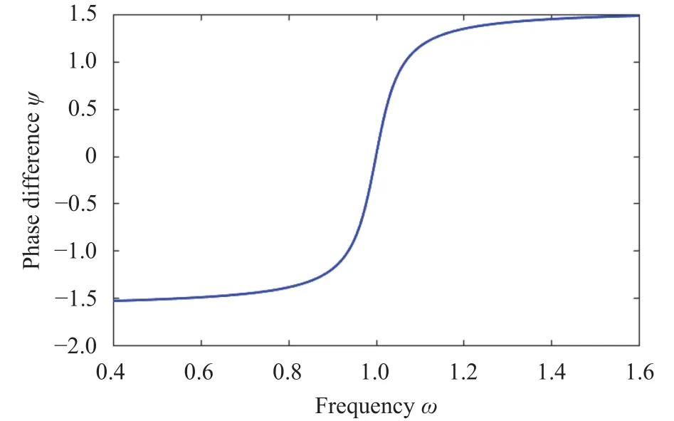
Fig. 4. Frequency phase diagram; V A=1 V, cA=cB=1/12,=0.01.
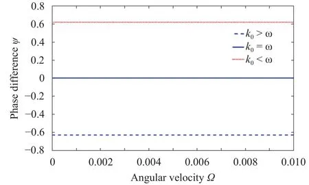
Fig. 5. Variation of phase difference with angular velocity; V A=1 V,cA=cB=1/12.

Fig. 6. Effect of the magnitude of the damping on the sense amplitude. a Frequency response in different damping conditions for V A=1 V,=0.01. b Amplitude varies with angular velocity in different damping conditions for V A=1 V,=1.
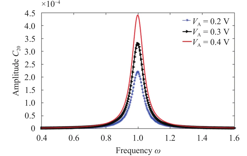
Fig. 7. Effect of different excitations on frequency response;=0.01,cA=cB=1/12.
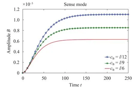
Fig. 8. Sense direction amplitude changes with time;=0.01, V A=1 V,=1.

One of the solutions to the non-homogeneous linear equations (11) is composed of a steady state solution and a transient solution. As shown in Fig. 8, the amplitude of the sense direction varies with time under different damping levels. The increase of damping reduces the transient response time to a certain extent,and reduces the influence on the measured angular velocity. As shown in Fig. 9, the sensitivity varies with the external excitation frequency under different damping levels, which leads to the lower sensitivity for larger damping. Hence a paradox appears:decreasing the damping can increase the sensitivity of the system, but also can promote the transient the time of transient response attenuation, which disturbs measuring the steady-state response in time. Therefore, it is important to control the damping within a certain range, during which the damping neither affects the measurement of the angular velocity and nor affects the sensitivity of the gyroscope.
In order to analyze the variation of natural frequency with angular velocity, the damping in Eq. (26) is now set zero. Then the following characteristic equation can be obtained

The eigenfrequencies of the drive direction and the sense direction can be obtained by taking the positive imaginary part of the solution as
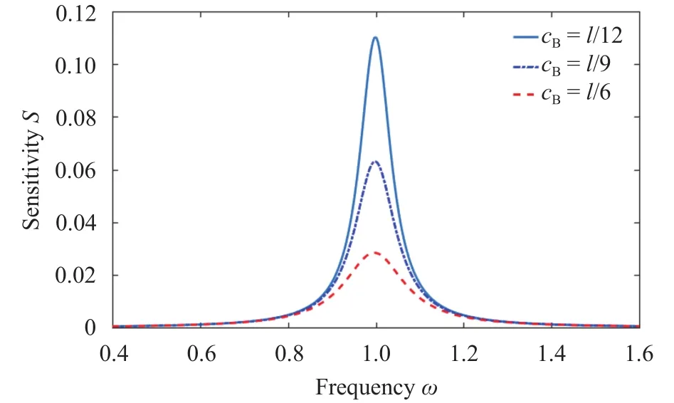
Fig. 9. Effect of damping on sensitivity;=0.01, V A=1 V.

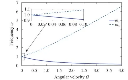
Fig. 10. Variation of natural frequency with angular velocity.
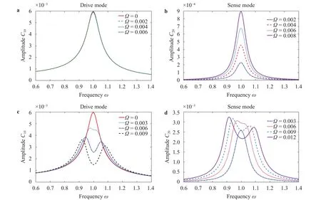
Fig. 11. The frequency response of driving direction and sensing direction at different angular velocities. a Drive mode: Curve of change in frequency response over a lower angular velocity range. b Sense mode: Curve of change in frequency response over a lower angular velocity range.c Drive mode: Curve of change in frequency response over a higher angular velocity range. d Sense mode: Curve of change in frequency response over a higher angular velocity range.
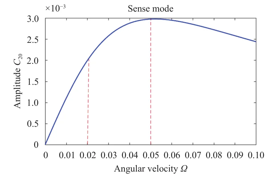
Fig. 12. Sense direction amplitude changes with angular velocity;V A=1 V, cA=cB=1/12,=1.
It can be seen from Eq. (31) that the natural frequencies are functions of angular velocity, and the two branches are shown in Fig. 10. In a wide range of angular velocity, the two natural frequencies exhibit a nonlinear relationship with velocity. At a lower value of angular velocity, the natural frequencies exhibits a linear relationship with the angular velocity, as shown in the inlet of Fig. 10. With introduction of rotational velocity, the natural frequency bifurcates into two: one increases and the other decreases with increasing velocity. Figure 11 shows the frequency amplitude responses of both directions at different angular velocities for the parametersVA=1 V,cA=cB=1/12. As shown in Fig.11(a), when the angular velocity (0~0.01) is very small, the amplitude keeps almost the same position in the drive direction. The angular velocity can be clearly detected by the different amplitudes in sense direction as presented in Fig. 11(b). However,with increase of the angular velocity, the amplitude decreases and frequency shifting occurs as presented in Fig. 11(c).However, in the real gyroscope structure, the drive direction of the gyroscope must be maintained at a certain amplitude, so a closed loop feedback control is required to keep the constant amplitude in the drive direction [25]. In Fig.11(d), responses seem complicated in the sense mode. When a certain angular velocity is applied, a unique amplitude should be sensed to measure the velocity. However, the frequency fall in between the two peaks give bad recognition degree, since the response amplitude is not varying monotonically with the input angular velocity.
As shown in Fig. 12, the amplitude of the sense direction changes with the angular velocity in the interval of 0 to 0.1. There are three stages of change in the Fig. 12. The first stage is from 0 to 0.02, and the amplitude varies linearly with the increase of angular velocity, since the angular velocity of this range is very small. The second stage is from 0.02 to 0.05, and the amplitude exhibits a nonlinear change with the increase of angular velocity.The third stage is from 0.05 to 0.1, and the amplitude decreases with the increase of the angular velocity. At this time, the angular velocity is large, and the resonance frequency shifting occurs significantly. The reason can be found in the result of Fig. 10: the gap between the two resonant frequencies in the sense direction increases as the angular velocity increases. Correspondingly, the two peaks of the amplitude are gradually moving away as the an-gular velocity increases in Fig. 11(d). Therefore, when the angular velocity is relatively large, the resonance point at the small angular velocity can no longer measure the angular velocity better, and the angular velocity must be measured at the low frequency point in Fig. 11(d).

Fig. 13. Time history. a Drive mode. b Sense mode.
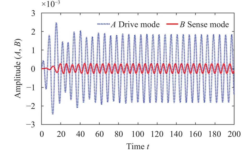
Fig. 14. Time history of the transfer of energy between drive and sense modes.
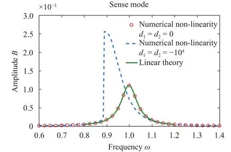
Fig. 15. Frequency response of sensitive directions in different situations (linearity vs. nonlinearity); VA=1,=0.01, cB=1/12.
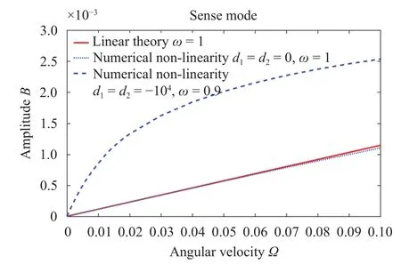
Fig. 16. Sense direction amplitude with angular velocity in three cases for VA=1, cB=1/12.
Linear analysis demonstrates the benefits of low frequency measurements at high angular speeds. In addition, as the angular velocity changes, the response of the sense direction is analyzed in detail. Although the same linear gyroscope was studied in Refs. [25, 27], these issues have not been discussed in depth.
In order to study the effect of nonlinearity on the performance of vibrating ring gyroscope, the original nonlinear governing equations (1) and (2) are numerically integrated using a fourth-order Runge-Kutta algorithm to analyze the dynamic nonlinear responses.
Figure 13 illustrates drive and sense modes response of the gyroscope for the parameterscA=cB=1/12,=0.01,VA=1 V,=1. It can be seen from the two plots that the oscillations of the two modes gradually fall in the steady state over time. At the beginning, the transient motions of two modes gradually vanish. Figure 14 present transfer energy between drive and sense modes due to Coriolis force.

Fig. 17. =0.01 time history of two modes (non-linearity, d1=d2=0, VA=1 V vs. linearity, VA=1 V). a Drive mode. b Sense mode.
There are two main nonlinear terms in the nonlinear dynamic equation: the effective Duffing coefficientd1and the intermodal coefficientd2, which are mainly caused by the elastic and electrostatic stiffness effects in the system. As shown in Fig. 15,the soften effect of the nonlinear terms can be found since the response curve is bent leftwards. It can be seen from Fig. 17 thatd1andd2play a major role in the nonlinear system, and other nonlinear terms in the equation have less influence on the dynamic response. Such nonlinearity in practice should be considered to improve the sensitivity of the gyroscope. In Fig. 16, the amplitude of the sense direction changes with angular velocity in three cases which are in resonance. Whend1andd2are not equal to zero, the response amplitude of the sense direction varies nonlinearly with angular velocity. Whend1andd2are equal to zero, the response amplitude of the sense direction varies linearly with angular velocity. This is close to the linear theoretical curve which is linear.
One key parameter that should be optimized in vibratory ring gyroscope design is the driving voltage. The relationship between the response amplitude and the driving voltage in both directions is revealed in Fig. 18. In a certain range of the drive voltage, the amplitudes of the drive direction and the sense direction increase as the driving voltage increases.
The nonlinear responses of the ring gyroscope for different drive voltages are obtained by the Runge-Kutta algorithm, as shown in Fig. 19. In a vibratory ring gyroscope, the amplitude response curves of both drive and sense direction exhibit weak nonlinearity at a drive voltage of 0.2 V. As the drive voltage increases, the resonance peaks in both directions shift to the left,which is obvious a soften phenomenon. Further a jump phenomenon can be found for the backwards frequency sweep.Hence although the high value of driving voltage increase the sense amplitude, it also brings in the multiple solutions of the responses, which leads to harder measurement of the angular velocity.
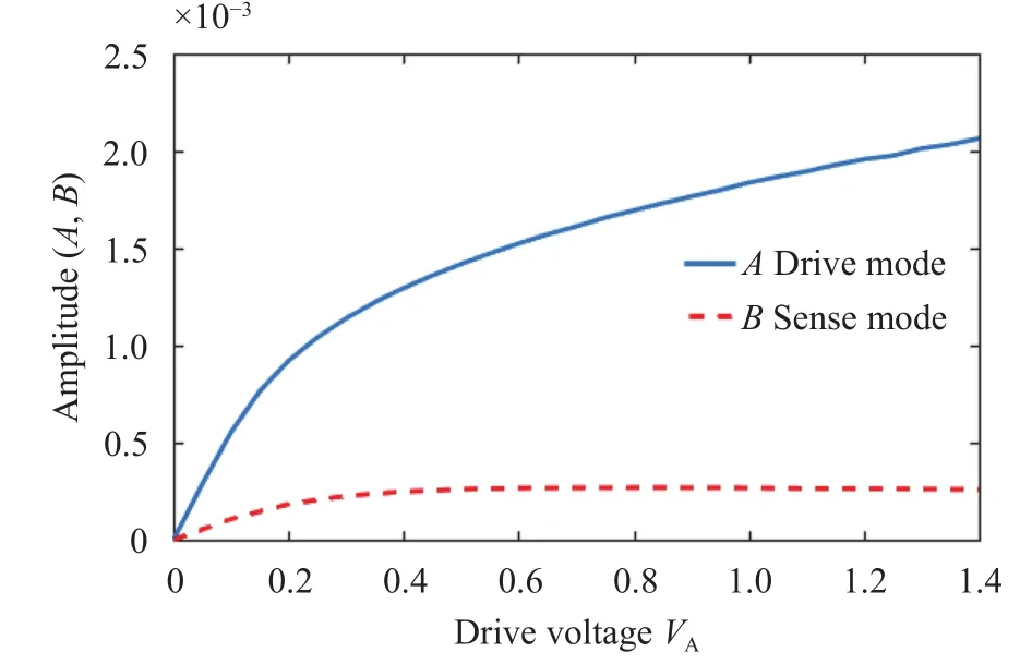
Fig. 18. The drive direction and the sense direction amplitude change with the increase of the driving voltage;=1, cA=cB=1/12.

Fig. 19. Nonlinear frequency response under different magnitude excitations (=0.01). a Drive mode. b Sense mode.
In summary, the dynamic response of the gyroscope is studied by linear analysis and nonlinear numerical analysis of the full coupled equations. In the linear case, the response characteristics of the gyroscope are investigated. Numerical methods are applied to study nonlinear dynamic equations, and the results of linear system and nonlinear system are compared to analyze nonlinear effects on gyroscopic systems.
In the linear vibration analysis of the vibrating ring gyroscope, when the angular velocity is relatively small, the amplitude of the sense direction is proportional to the angular velocity. When the angular velocity is larger, it is more effective to measure angular velocity at lower frequencies. Damping affects both transient response time and system sensitivity, so it is important for the gyroscope system to choose an appropriate damping. Additionally, the nonlinearity, which is mainly caused by geometric elastic effects and electrostatic stiffness, should be considered in the sensitivity of the gyroscopes. Due to the nonlinear terms, higher value responses increase the ability of measurement, but present multiple solutions, which leads to confused determination of angular velocities.
Acknowledgement
This work is supported in part by the National Natural Science Foundation of China (11672007, 11672189, and 11290152)and the Beijing Natural Science Foundation (3172003).
杂志排行
Theoretical & Applied Mechanics Letters的其它文章
- Data-driven computing in elasticity via kernel regression
- The effects of mean sea level rise and strengthened winds on extreme sea levels in the Baltic Sea
- New interpretation of specific sign of Reynolds stress in the boundary layer on a flat plate
- An improved smoke-wire flow visualization technique using capacitor as power source
- Head-on collision between two hydroelastic solitary waves with Plotnikov-Toland's plate model
- Structure-preserving approach for infinite dimensional nonconservative system
