Robust flat filtering DSP based control of the boost converter
2016-05-14HeberttSIRARAMIREZArturoHERNaNDEZMeNDEZJesusLINARESFLORESAlbertoLUVIANOJUaREZ
Hebertt SIRA-RAM´IREZ ,Arturo HERNaNDEZ-MeNDEZ ,Jes´us LINARES-FLORES †,Alberto LUVIANO-JUaREZ
1.Department of Electrical Engineering,Mechatronics Section,CINVESTAV-IPN,Av.IPN No.2508,Col.San Pedro Zacatenco 07360,D.F.Mexico,Mexico;
2.Universidad Tecnol´ogica de la Mixteca,Carretera a Acatlima Km.2.5,Huajuapan de Le´on,Oaxaca,Mexico;3.UPIITA-IPN,D.F.Mexico,Mexico
1 Introduction
In spite of its low-order and its bi-linear nature,the boost converter is a nonlinear DC-to-DC power conversion circuit with several challenging features:1)The output voltage,which is the variable to be regulated,is a non-minimum phase variable.2)System variables exhibit stringent physical constraints:The control input is binary-valued and its average magnitude value is uniformly bounded.Additionally,the output voltage values must operate above the constant input battery voltage.3)The most common exogenous disturbances(battery voltage fluctuations and load current disturbances)fail to comply with the celebrated matching conditions.4)The load resistance is,generally speaking,of unknown nature.The control input is,necessarily,discontinuous as represented by a switch position function(See Sira-Ram´ırez and Silva-Ortigoza[1]).The boost converter is,however,differentially flat(See Fliess et al.[2],Sira-Ram´ırez and Aggrawal[3]and J.Levine[4]).This important feature generally alleviates and trivializes the control design problem in several aspects(exact linearization,trajectory planning,etc.),provided all endogenous nonlinearities are perfectly known.Our purpose is to propose a method which handles those cases of exogenously perturbed nature where the acting endogenous non-linearities are largely unknown or disregarded.
Flat filtering constitutes a reinterpretation of GPIC(See Fliess et al.[5])in the form of classical compensation networks(CCN).Roughly speaking,any linear controllable system whose output is the Brunovski’s output can be output regulated with the help of a well tuned proper linear filter and a suitable linear combination of the available internal states of such filter.Here,it is shown that such classical tool is also capable of efficiently handling control tasks on perturbed linearizable nonlinear systems(i.e.,flat systems),such as the boost converter,including unknown,or neglected,nonlinearities,exogenous disturbances,and un-modeled dynamics;in a fashion similar as these uncertainties are handled in ADRC schemes(See Han[6],Zheng et al.[7,8],and Guo et al.[9–11],and a recent survey by Madonski and Herman[12]).
ADRC was first initiated by Han[6],as a robust design technique for disturbance rejection in nonlinear system with parameteruncertainties and significantexternaldisturbances.The uncertainties are to be canceled by a nonlinear control law[13].ADRC has found remarkable applications in industry,such as in power filter design[14,15],a series,LC,filtered active damper[16],actuators[17],rotatory speed regulation[18],flywheel energy storage system[19],power plant control[20],and so on.Recently,Sira-Ram´ırez proposed an ADRCapproach from the perspective of differential flatness[21].Gao[22]proposed a simplified linear version of the original ADRC approach in 2003,where all the poles of the ESO and the closed-loop characteristic equation are placed in the same location,and thus there is only one parameter to be tuned.
Sun and Gao[23]present a DSP-based active disturbance rejection control design for a 1-kW H-bridge DC-DC powerconverter.They implementthe active disturbance rejection control into a digital control board based on the TMS320C6711 digital signal processor chip,where they show the advantages and flexibilities of the control method.Due to flexibility and autonomy that offers a digital signal processor chip,we propose a robust flat filtering DSP-based control of the boost converter,which does not use an Extended State Observer,and has the characteristic of taking into consideration the original system order in a time-varying simplified model while avoiding algebraic estimation techniques.Thus,the contributions of this paper are:1)the design of a robust flat filtering control for the highly perturbed switched boost converter circuit,and 2)implementation of the robust flat filtering control,together with the trajectory desired reference of the flat output onTMS320F28335 DSP board(See Fig.1).
The paper is organized as follows.Section 2 describes the main features of the switch controlled boost converter system.It presents its state average model and establishes its flatness property.This section also formulates the output voltage reference trajectory tracking problem to be solved in an indirectmannervia the use of the flatness property enjoyed by the total average stored energy[24].A flat filter based controller is first proposed for the trajectory tracking in the ideally unperturbed but uncertain boost case.
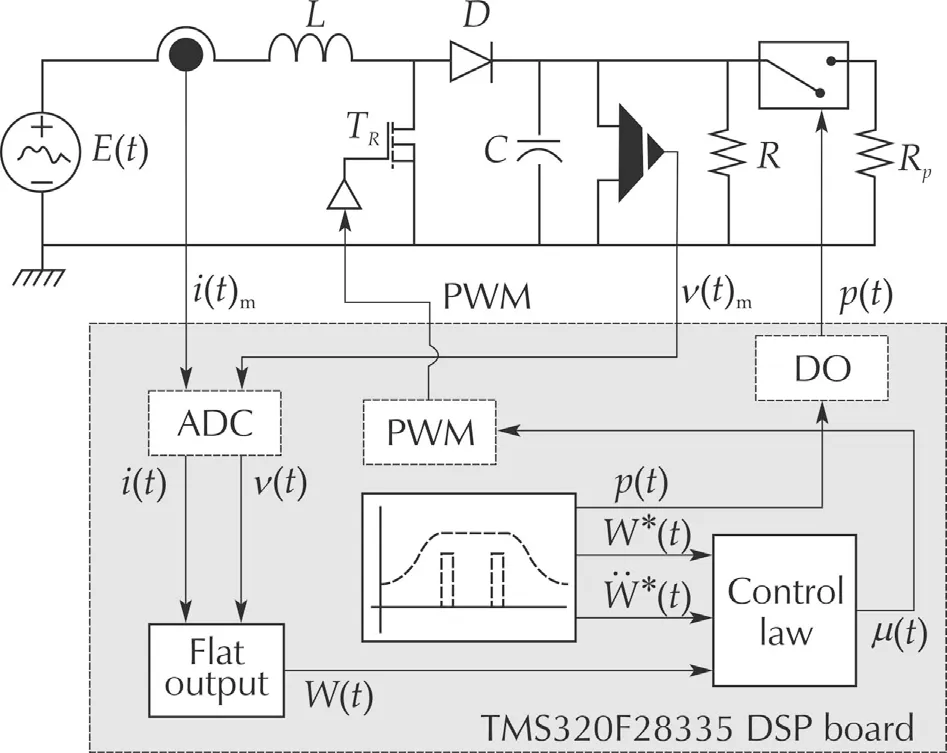
Fig.1 Flat filtering DSP based control of the boost converter.
Section 3 considers the fully exogenously perturbed uncertain boost converter case and shows that exactly the same flat filter based controller designed for the unperturbed case,also efficiently regulates the highly perturbed uncertain converter thus demonstrating the remarkable robustness of the method.Section 4 describes the experimental setup,and discusses the simulation and experimental results.Section 5 is devoted to some conclusions and presents suggestions for further research.An appendix at the end of the article contains,via an illustrative example,an intuitive justification of the proposed approach.
2 The boost converter
2.1 Generalities about the boost converter circuit
A simplified,unperturbed,model of the boost converter(See Fig.1)is described by

wherevis the output capacitor voltage,iis the inductor current,Eis the constant voltage value of the battery,Ris the load resistor whileLandCare the inductance and capacitance parameters.The control inputuis a binary-valued switch position functionu∈{0,1}.
Astate average modelof the circuit,described in(1),is obtained by replacing the control inputuby a smooth input variable μ∈[0,1](See[1]).For simplicity,we retain,in the state average model of the circuit,the same notation for the current and voltage variables,iandv,in an evident abuse of notation.

The equilibria,for constant values of the input μ=¯μ,can be obtained in a parameterized form in terms of the corresponding output voltage equilibrium value¯v.

The factthat,necessarily,¯μ∈[0,1]implies that¯v?E.Thus,the boost converter circuit amplifies,at the outputv,the battery voltage,E,and the corresponding steady state restriction must not be violated.
The zero dynamics corresponding to the sustained voltage equilibrium:v=¯v,is given by the unstable differential equation for the average inductor current:

thus,the output voltage is a non-minimum phase variable.The average boost converter model is locally differentially flat,with flat output given by the average total stored energy,

Indeed,the following set of coordinate transformations

constitutes a local diffeomorphism(which is singular along the lines:v=0 andi=RCE/(2L)in the average state space).The outputWis,as it is easily verified,relative degree 2.The inverse transformation is simply:

where the positive sign in the root is taken to comply with the physically meaningfulrestrictions.The previous state coordinate transformation exactly locally linearizes the total average stored energy dynamics after rendering it in Isidori’s canonical form([25]):

with rather involved expressions for the nonlinearities,ψ and φ not presented,or used,here.
The equilibrium of the average total stored energy,corresponding to an operating point(¯i,¯v),is given,in terms of the voltage equilibrium value,¯v,by,

2.2 Problem formulation for the unperturbed case
Clearly,a desired rest-to-rest maneuver between two given equilibrium values,¯vinit,¯vfinal,for the average output voltagev,finds a unique pair of corresponding equilibrium values,¯Winit,¯Wfinal,for the average stored energyW.As a consequence,a reference trajectory tracking problem,defined on the unperturbed model,(2),that seeks to force the average output voltagevfrom an initial equilibrium value to a desired final equilibrium value may be(indirectly)solved in terms of a corresponding trajectory tracking problem for the linearizing(flat)outputW(See Fliess et al.[26]).
Instead of using the transformed canonical dynamics(8)in terms of(x1,x2)=(W,˙W),for the total average stored energy dynamics,we examine the relation between the second-order time derivative ofWand the average control input μ in terms of the original average model state variablesiandv.

Suppose it is desired to achieve a rest-to-rest transfer between a given initial and a desired final average equilibrium value forthe average outputvoltagev.Borrowing concepts from ADRC,which are intimately related also to MFC,we intend to largely ignore the nonlinearities appearing in the total stored energy second derivative expression¨W.We simplify the model to a completely unstructured model.Consider the input channel modified dynamics with a state an input dependent total perturbation term:

The next crucial and controversial step,has been recently rigorously justified in([9–11])in the context of ADRC and in the work of Fliess and Join[27]in the context of MFC.This consists in replacing the endogenous nonlinearity ξ(i,v,μ)=z1by a low degree,unstructured time polynomial model,represented as a local internal disturbance model(described by a corresponding low-order homogeneous linear state model)in the simplified dynamics.This is achieved by either letting:˙z1=0 in the zeroth degree polynomial model case,or ˙z1=z2,˙z2=0,in the first degree polynomial case,and so on.This step is performed totally disregarding the state and control input dependance of the additive nonlinearities in the additive term:ξ(i,v,μ).The choice of the nonzero constant,a,replacing the nonlinear,state and input-dependent gain,turns out to be,more surprisingly,quite arbitrary(see[6]);although educated guesses,or,alternatively,local algebraically based parameter identification procedures,may prove to be substantially effective(See Sira-Ram´ırez et al.[28]).
The model to be controlled,using a third-order local homogeneous state model for the state and input dependent nonlinearities,ξ(i,v,μ)=z1,is thus given by

The tracking erroreW=W-W*(t)evolves governed by


The original system,being second-order,requires a first-order(lead)compensation network(see the appendix).However,the second degree local internal time polynomial model of the additive disturbance may be ideally annihilated,according to the internal model principle[29],by a third-order integration term appearing in the denominator of the controller transfer function.This leads to the following compensation scheme1Note that the internal model of the state and input dependent additive perturbation may even be proposed to be represented by a first-order homogeneous system.This simply means that the perturbation is ultra-locally([27]and[31])approximated by a piece-wise constant function of time instead of a piece-wise linear time function(see the appendix).:

A state space realization of the CCN,as a flat filter,is readily obtained as follows:
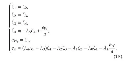
eWfis the flat output of the classical compensation network.The characteristic polynomial of the normalized closed-loop system,ignoring the attenuated effects of the nonlinearities and disturbances,is given by

2.3 The perturbed case
Considerthe following nonlinearmodelofa perturbed boost converter(See Fig.2)

whereiis the inductor current,vis the output capacitor voltage,E(t)is a time-varying disturbance voltage value of the power supply.Ris the known value of the load resistor,v/R||Rprepresents an unknown time-varying load disturbance drain current(I(t)L).Pis a digital signal which controls a bidirectional switch.The control inputuis,as before,the binary-valued switch position functionu∈{0,1}.

Fig.2 A perturbed boost converter.
It is desired,in spite of the effects of the total disturbance,affecting the system,to transfer the total stored energy,

from an initial equilibrium value¯Winittowards a final desired equilibrium value,¯Wfinal,in a pre-specified amount of time,while tracking a given smooth reference trajectoryW*(t)satisfying the initial and final restrictions.This stored energy maneuver is motivated by the desire to smoothly transfer the nominal output voltage level from a corresponding initial equilibrium value towards a final desired equilibrium value.The tracking error,eW=W-W*(t),willbe assumed to evolve governed by the perturbed dynamics,

A local first degree polynomial model is adopted for the unknown disturbance ξ,represented by a secondorder homogeneous pure integration subsystem.
3 Experimental setup
The experimental setup,shown in Fig.3,is composed of a boost converter designed to operate in continuous conduction mode at a 20 kHz switching frequency,a pair of sensors,one to measure the inductor current,and the other to measure the output capacitor voltage.An additional circuit is used to enable/disable a disturbance resistive load triggered by means of an output digital signalp(DSP).The nominal values of the components and manufacturer information about the sensors are shown in Fig.3.
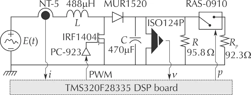
Fig.3 General scheme of the experimental platform(DC/DC boost converter).
The algorithm of the control and the desired reference trajectory were implemented using aTMS320F28335 DSP board,where,the complete scheme operates at a fixed sampling rate of 1 MHz.The DSP clock frequency is adjusted to 150 MHz.Two ADCs,a PWM generator and a digital output are required.The program takes up 23%of the available RAM(7.821 KB).The elements of the control system shown in Fig.4 and these are described below.
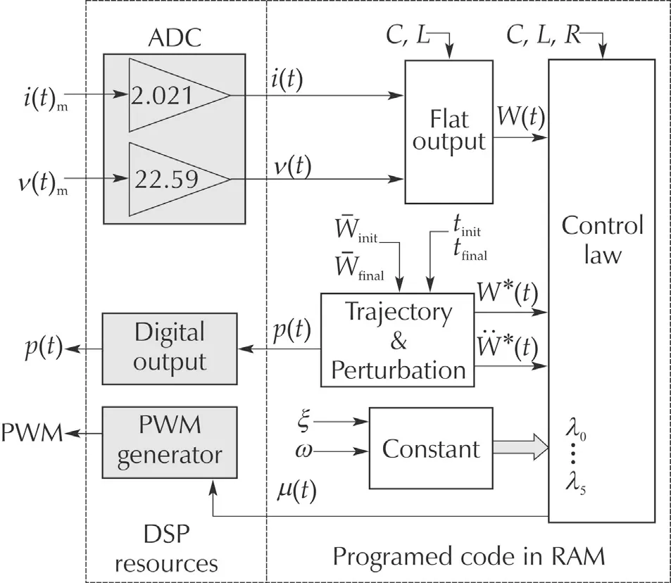
Fig.4 General scheme of the experimental platform(DSP board).
The measured signalsiandvare digitized with two 12-bitADC with a gain calibration of2.021 and 22.59 respectively.The control input μ adjusts the duty cycle of a PWM module,which is set to a frequency of 20 kHz.The disturbance signalp,use a digital output port of the DSP board,which has a voltage level of 3.3 V whenp=1.Therefore,a pre-amplification step is required to activate the relay RAS-0910.The algorithm of control is composed of four modules,as shown in Fig.4.TheFlat outputmodule obtains the total energy stored in the systemW(t)from(8)and requires the signalsi(t),v(t),and the nominal values ofLandC.TheTrajectory&perturbationmodule generates the reference pathW*(t),as follows:under equilibrium conditions,the average values ofthe boostconvertervariables,(1),written in terms of the desired constant average output voltage¯v=Vd,are given by


withf(t,tinit,tfinal)∈[0,1],∀t∈[tinit,tfinal]being a 10th-order Bezier polynomial(See[30])given by
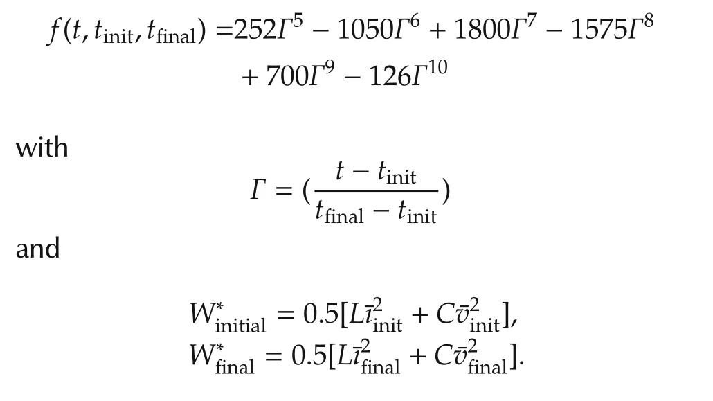
The initial and final values of the average output voltagevand the average inductor current,iare given by

The system parameters:RandE,are assumed to be continuously time varying in an unknown manner.These parameters are required to calculate the rest to rest reference trajectory for the flat output and the gains in the feedback control law.For theControl lawmodule,equations(15),corresponding to the flat filter controller are used.To generate the code of this module,we use the implicit Euler method to pass the equations to their discrete form.That is to say,for a time function ν(t):
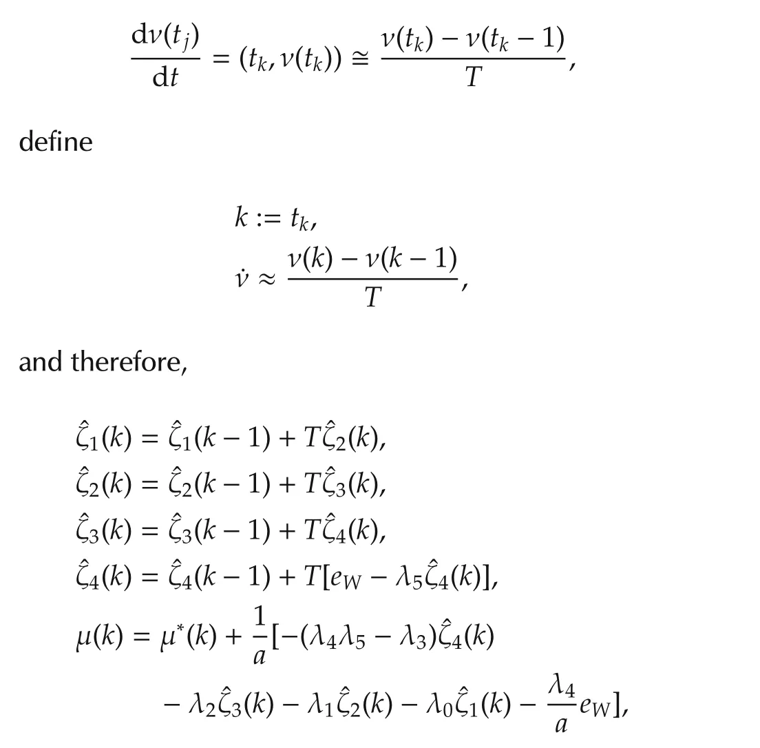
where ν(k)is the current sample,and ν(k-1)is the previous sample andTis the sampling period(1μs).The evolution ofeμ(t)will asymptotically exponentially converge to zero if and only if the coefficients of the linear feedback tracking controller are chosen in such a manner that the characteristic polynomial of the closedloop system isHurwitz,i.e.,all roots of the polynomialp(s)(16),in the complex variables∈C,lie in the left half of the complex plane.With ζ=0.707 and ω=15,the poles placement in closed-loop system are:p1,2=-0.35514-14.793j,p3,4=-0.36268+15.201j,p5=-3.856,andp6=-58.338.Therefore,the tracking erroreμ(t)in closed is asymptotically exponentially converge to zero.
3.1 Simulation results for the unperturbed case
A boost converter,with parametersL=488×10-6H,C=470×10-6F,andR=95.8Ω,is required to transfer its output equilibrium voltage¯vinitial=30 V towards a final desired equilibrium¯vfinal=45 V.The battery nominal value isE=20 V.
In order to achieve a smooth rest-to-rest maneuver of the output voltagev,from the initial equilibrium value of¯vinitial=30 V,towards the final desired equilibrium value of¯vfinal=45 V,in a prescribed time interval of 1 s,a corresponding smooth trajectory,W*(t),of the total stored energyWwasprescribed from the corresponding initial value¯Winitial=0.2149 J towards the final desired value,¯Wfinal=0.4835 J,also in a time intervalof1 s starting att=2 s,then the reference trajectory is repeated in the opposite direction after 8 s.The desired rest-torest stored energy trajectory,W*(t),was prescribed using a classical Bezier time-polynomial of 10th degree smoothly interpolating between the required initial and final values forW.
Fig.5 depicts the PSIM2PSIM is a simulation software specifically designed for power electronics and motor drives.With fast simulation and friendly user interface,PSIM provides a powerful simulation environment for power electronics,analog and digital control,magnetics,and motor drive system studies.simulations results of the performance of the linear flat filtering based controller for the boost converter in a desired average total stored energy transfer from an initial operating equilibrium towards a final,desired,equilibrium,indirectly achieving a smooth voltage increase between corresponding equilibrium values.In Fig.6,the average controlinputis seen to comply with the uniform boundedness requirement μ(t)∈ [0,1]during the required maneuver.
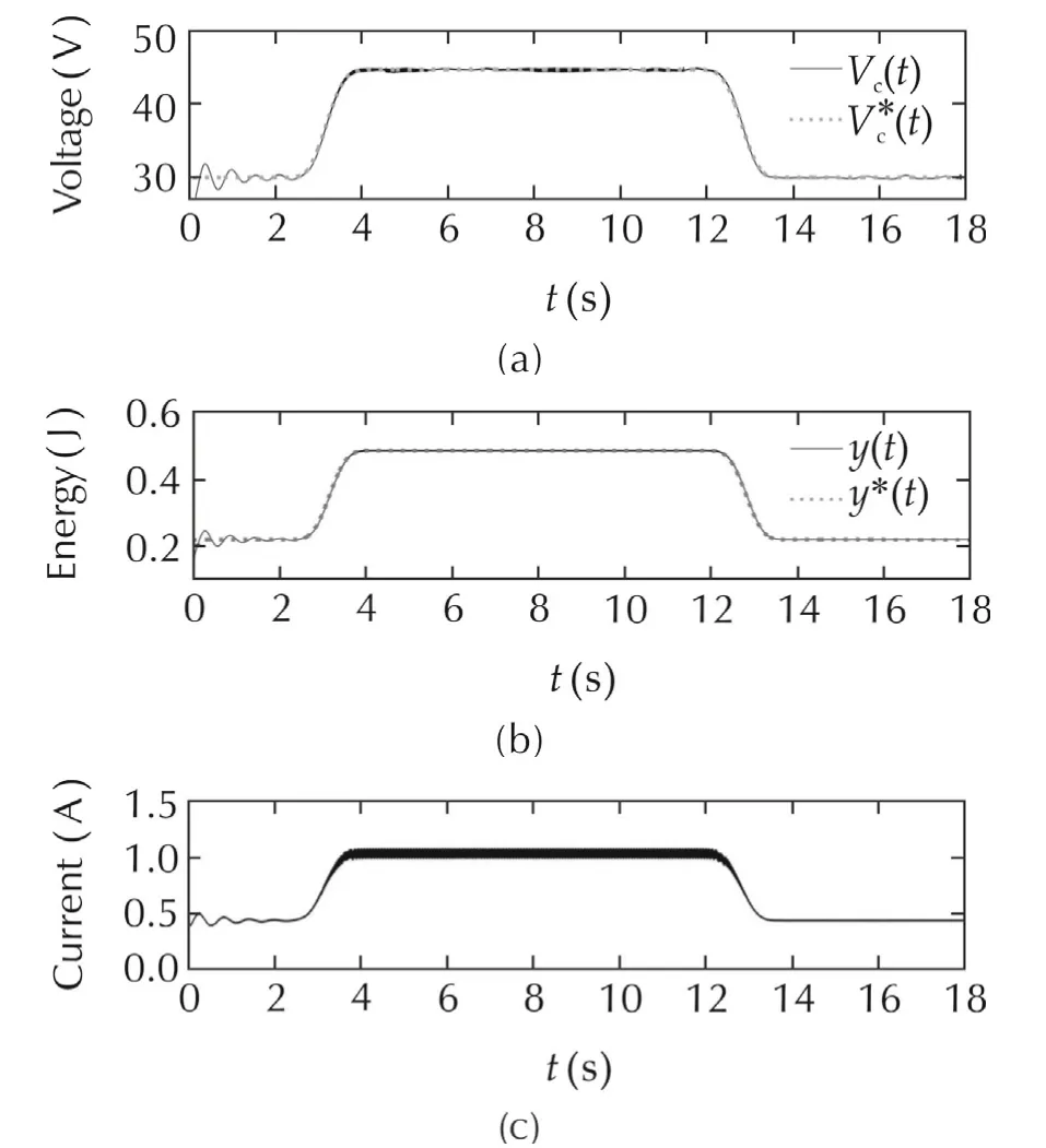
Fig.5 Performance of flat-filter based controller for a boost converter,on a unperturbed case.(a)Capacitor voltage responses.(b)Total stored energy responses.(c)Inductor current response.
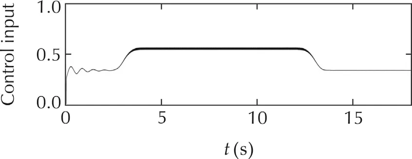
Fig.6 Switched control input and average control input produced by the flat filter based controller.
3.2 Simulation and experimentalresults forthe perturbed case
We apply the same flat filtering based controller previously designed for the unperturbed case and adopt the same output voltage rest-to-rest maneuver.For this test,we programme the unknown time-varying function of the batteryE(t)V,as follows:

Also,we change the outputresistance valueRthrough the connection with other perturbation parallel resistanceRp,the connection and disconnection of the perturbation resistance is controlled by means of an output digital signalp,the equivalent resistance of the boost power converter system,is given by
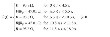
Through the variations of the power source and output resistance,we test the performance of the proposed control.In the first place,we obtain the PSIM simulations results of the performance flat-filter control under variations of power source,and under sudden output resistance change.In the second place,we obtain the experimental results of the performance flat-filter control with these same variations.
3.2.1 PSIM simulations results
Fig.7 shows on the top graph the output voltage response of boost converter,while the upper graph shows the flat output response of the boost converter system,under the variations of power source and output load resistance,which are shown on Fig.8.The ISTE(integral square tracking error)of output voltage performance index shows a good performance in spite of the variations of power source and output load resistance.Thus,we observe that the linear flat filtering based controller achieves the robustness on thenon-minimum phasevariableof the boost converter system for the perturbed case(See Fig.9).Fig.10 shows the inductor and output resistance current responses under the power source and output resistance variations,we observe that the amplitude ofthe currents is incremented when the nominal value of output resistance is reduced in the intervals given by(20).
Fig.8 shows on the top graph the comparison between the flatfiltercontroland robustnonlinearadaptive control[24]of the output voltage,where we see that the flat filter response do not present a voltage overshoot in the initial condition,while the robust adaptive response present a voltage overshoot.Additionally,we see that the responses in steady-state,the flat filter controller response has a light damping,and the robust adaptive controller response has nothing of damping.The same occurs for the flat output responses of both controllers,this is shown on the upper graph of Fig.8.
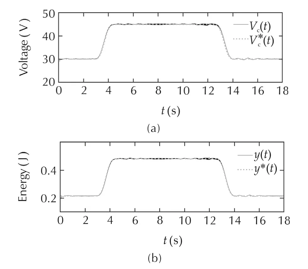
Fig.7 PSIM simulation results:Output voltage response and flat output response for a stored energy trajectory tracking task,with power source and output resistance variations.(a)Capacitor voltages.(b)Total stored energy responses.
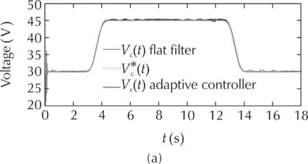
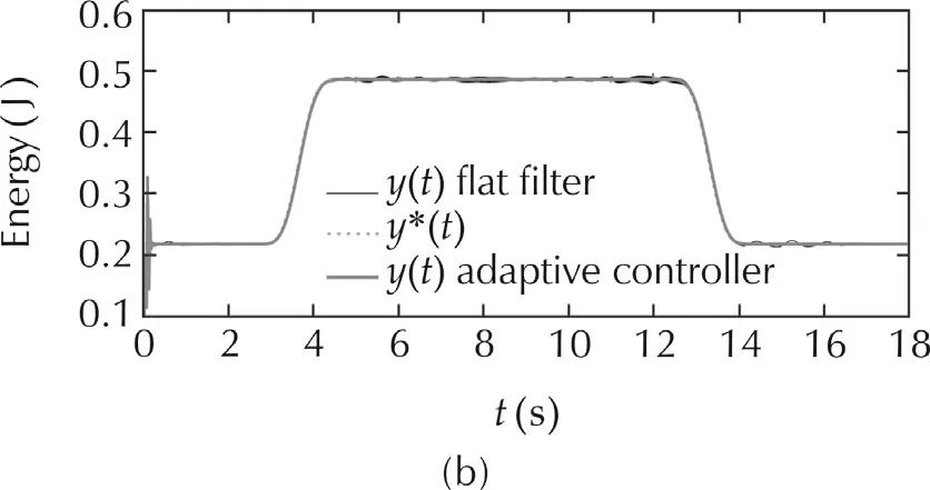
Fig.8 PSIM simulation results:Output voltage responses and flat output responses for a stored energy trajectory tracking task,with power source and output resistance variations.(a)Capacitor voltages.(b)Total stored energy responses.
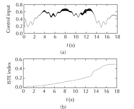
Fig.9 PSIM simulations results:Average flat filter control and integral square tracking error of the output voltage of boost power converter.(a)Average control input.(b)ISTE index.
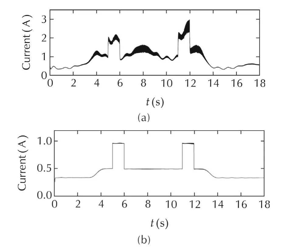
Fig.10 PSIM simulations results:Inductor current response and output load current response for a stored energy trajectory tracking task,with power source and output resistance variations.(a)Inductor current response.(b)Load current disturbance.
3.2.2 Experimental results
Fig.11 shows the experimental results of the output voltage and flat output of the boost power converter.We observe that the output voltage and output flat responses of the system in steady-state present a light damping due to damping coefficientofthe flat-filtercontroller,which was tuned with a value of ζ=0.707,this produces responses of under-damped type(See Section 3).
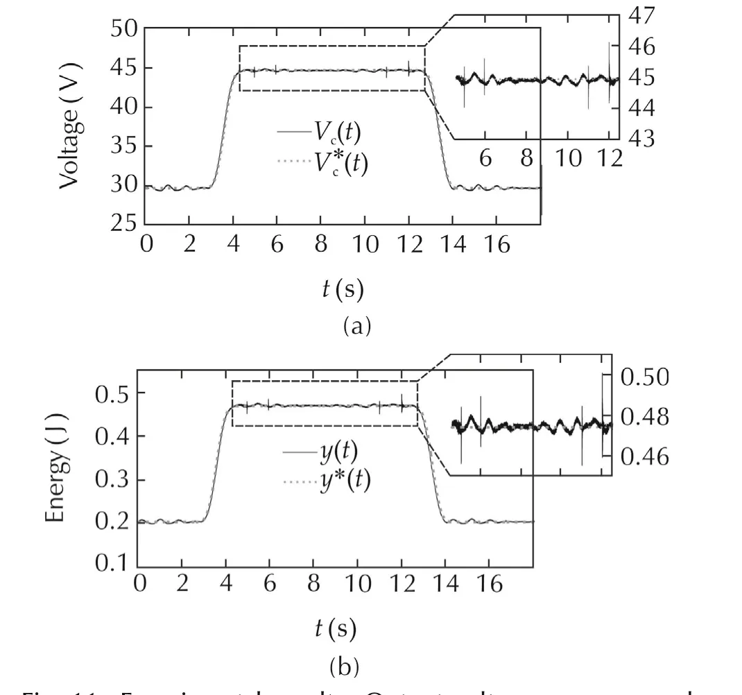
Fig.11 Experimental results:Output voltage response and flat output response for a stored energy trajectory tracking task,with power source and output resistance variations.(a)Capacitor voltages.(b)Total stored energy responses.

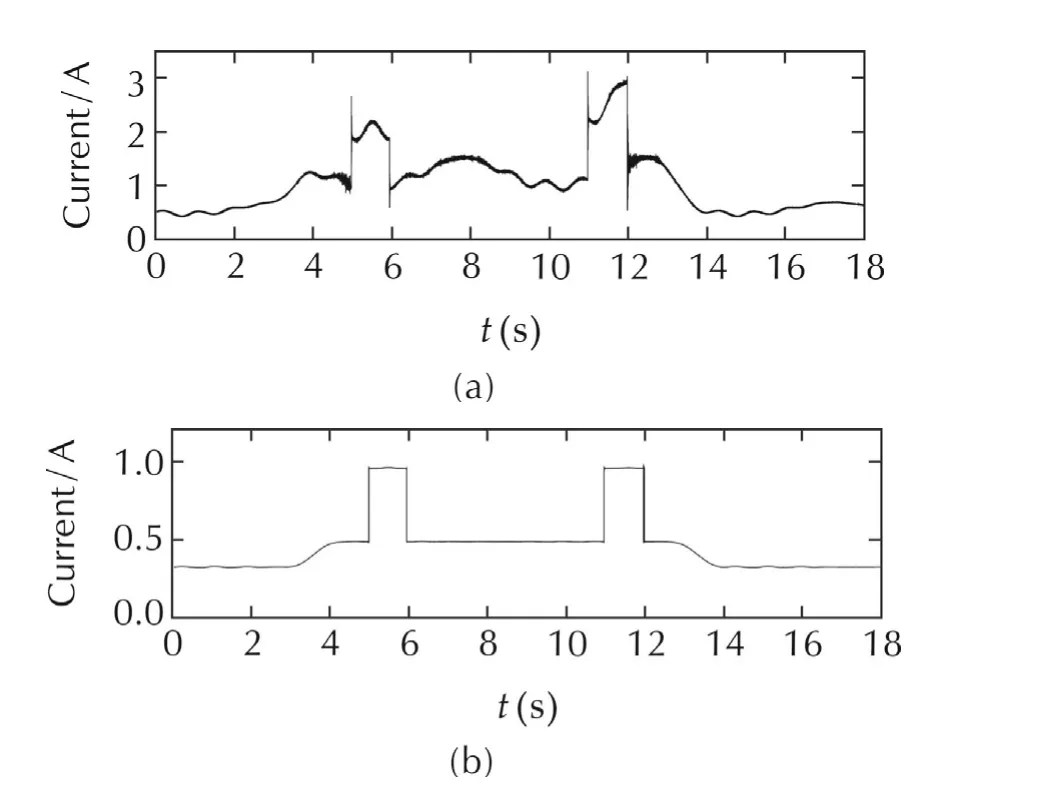
Fig.13 Experimental results:Inductor current response and load current response.(a)Inductor current response.(b)Load current disturbance.
4 Conclusions
In this article,we have introduced an application of a remarkable new property of flatness,summarized as follows:any linear controllable system whose flat output(or Brunovski output)coincides with the system output,may be controlled,in stabilization or trajectory tracking tasks,by means of a linear,well tuned,stable linear filter alone.The filter processes,respectively,the system output,or the system output trajectory tracking error.A linear combination of the internal states of the linear filter conform the required stabilizing feedback law.The coefficients of the linear filter,which turns out to be also flat in a filtering context,are uniquely deter-mined in a rather trivial manner involving only an overall pole placement effort for the closed-loop stability of the system.The flat filter constitutes a reinterpretation of the classical compensation networks for linear systems.The classical compensation networks are shown to be totally equivalent to the well known GPIC’s based on integral reconstructors.GPIC efficiently evade the need for asymptotic state observers.The striking fact,coincident in a dual manner,and without need for extended observers,with ADRC schemes is that the above linear resultmay be easily extended to the approximate control ofnonlinearuncertain,and exogenously perturbed,nonlineardifferentially flatsystems.As in ADRC,we also use a controlinputchanneltrivialization in the form ofa constant gain.The proposed robust flat filtering based controller also shares a philosophical viewpoint with MFC schemes.The fundamental idea of MFC,in high dimensional input-output systems,is that of viewing additive endogenous and exogenous total disturbances,as well as unknown nonlinear control input gains,as on-line piece-wise algebraically identifiable time signals.These are ascribed to a first,or,at most,second order,reference model system on which a P,PD or PID controller is readily designed while periodical updating of the local on-line identifications is performed.The synthesized control input is then shared with the actual plant.In robust flat filtering controls we only respect the system order,treat nonlinearities as unknown time signals that can be significantly attenuated by a linear classical compensation network including a suitable pure integration internal model for the effects of the total unknown disturbances.The nonlinear control input gain is arbitrarily replaced by a constant gain.
[1]H.Sira-Ram´ırez,R.Silva-Ortigoza.Control Design Techniques in Power Electronics Devices.London:Springer,2006.
[2]M.Fliess,J.Levine,Ph.Mart´ın,et al.Flatness and defect of nonlinear systems:Introductory theory and examples.International Journal of Control,1992,61(6):1327–1361.
[3]H.Sira-Ram´ırez,S.K.Aggrawal.Differentially Flat Systems.New York:Marcel Dekker Inc.,2004.
[4]J.Levine.Analysis and Control of Nonlinear Systems:A Flatness Based Approach.Berlin:Springer,2009.
[5]M.Fliess,R.Marquez,E.Delaleau,et al.Correcteurs proportionnels-int`egraux generalises.ESAIM,Control,Optimization and Calculus of Variations,2002,7(2):23–41.
[6]J.Han.From PID to active disturbance rejection control.IEEE Transactions on Industrial Electronics,2009,56(3):900–906.
[7]Q.Zheng,Z.Chen,Z.Gao.A practical approach to disturbance decoupling control.Control Engineering Practice,2009,17(9):1016–1025.
[8]Q.Zheng,L.Gao,Z.Gao.On validation of extended state observer through analysis and experimentation.ASME Journal of Dynamic Systems,Measurement and Control,2012,134(2):1–6.
[9]B.Guo,Z.Zhao.Weak convergence of nonlinear high-gain tracking differentiator.IEEE Transactions on Automatic Control,2013,58(4):1074–1080.
[10]B.Guo,Z.Zhao.On the convergence of an extended state observer for nonlinear systems with uncertainty.Systems&Control Letters,2011,60(6):420–430.
[11]B.Guo,Z.Zhao.On the convergence of the nonlinear active disturbance rejection control for MIMO systems.SIAM Journal of Control and Optimization,2013,51(2):1727–1757.
[12]R.Madonski,P.Herman.Survey on methods of increasing the efficiency of extended state disturbance observers.ISA Transactions,2014,56:18–27.
[13]W.Chen,J.Yang,L.Guo,et al.Disturbance observer-based control and related methods–an overview.IEEE Transactions on Industrial Electronics,2015,63(2):1083–1095.
[14]G.A.Ramos Fuentes,J.A.Cortes-Romero,Z.Zou,et al.Power active filter control based on a resonant disturbance observer.IET Power Electronics,2015,8(4):554–564.
[15]Q.Zhong,Y.Zhang,J.Yang,et al.Non-linear auto-disturbance rejection controlofparallelactive powerfilters.IETControlTheory&Applications,2009,3(7):907–916.
[16]X.Wang,Y.Pang,P.C.Loh,et al.A series-LC-filtered active damperwith grid disturbance rejection for AC power-electronicsbased power systems.IEEE Transaction on Power Electronics,2015,30(8):4037–4041.
[17]S.Li,J.Li,Y.Mo.Piezoelectric multimode vibration control for stiffened plate using ADRC-based acceleration compensation.IEEE Transactions on Industrial Electronics,2014,61(12):6892–6902.
[18]H.Sira-Ramirez,J.Linares-Flores,C.Garc´ıa-Rodr´ıguez,et al.On the control of the permanent magnet synchronous motor:an active disturbance rejection control approach.IEEE Transactions on Control System Technology,2014,22(5):2056–2063.
[19]X.Chang,Y.Li,W.Zhang,et al.Active disturbance rejection control for a flywheel energy storage system.IEEE Transactions on Industrial Electronics,2015,62(2):991–1001.
[20]H.Hwang,L.Wu,J.Han,et al.A new synthesis method for unit coordinated controlsystem in thermalpowerplant-ADRC control scheme.International Conference on Power System Technology,Singapore:IEEE,2004:133–138.
[21]H.Sira-Ram´ırez,A.Oliver-Salazar.On the robust control of buckconverter DC-motor combinations.IEEE Transactions on Power Electronics,2013,28(8):3912–3922.
[22]Z.Gao.Scaling and bandwidth-parameterization based controller tuning.Proceedings of the American Control Conference,Denver,Colorado:IEEE,2003:4989–4996.
[23]B.Sun,Z.Gao.A DSP-based active disturbance rejection control design for a 1-kW H-bridge DC-DC power converter.IEEE Transactions on Industrial Electronics,2005,52(5):1271–1277.
[24]J.Linares-Flores,A.Hernandez-Mendez,C.Garc´ıa-Rodr´ıguez,et al.Robust nonlinear adaptive control of a boost converter via algebraic parameter identification.IEEE Transactions on Industrial Electronics,2014,61(8):4105–4114.
[25]A.Isidori.Nonlinear Control Systems.New York:Springer,1995.
[26]M.Fliess,H.Sira-Ram´ırez,R.Marquez-Contreras.Regulation of non-minimum phase outputs:a flatness based approach.Perspectives in Control,London:Springer,1998:143–163.
[27]M.Fliess,C.Join.Model-free control.International Journal of Control,2013,86(12):2228–2252.
[28]H.Sira-Ram´ırez,C.Garc´ıa-Rodr´ıguez,J.Cortes-Romero,et al.Algebraic Identification and Estimation Methods in Feedback Control Systems.Chichester:John Wiley&Sons Ltd.,2014.
[29]B.Francis,W.M.Wohnam.The internalmodelprinciple forlinear multivariable regulators.Applied Mathematics and Optimization,1975,2(2):170–194.
[30]J.Linares-Flores,C.Garc´ıa-Rodriguez,H.Sira-Ram´ırez,et al.Robust backstepping tracking controller for low speed PMSM positioning system:design,analysis,and implementation.IEEE Transactions on Industrial Informatics,2015,11(5):1130–1141.
[31]H.Sira-Ram´ırez,J.Linares-Flores,A.Luviano-Juarez,et al.Global ultramodels and active disturbance rejection control of nonlinear differentially flat systems.Revista Iberoamericana de Automatica e Informatica Industrial,2015,12(2):133–144.
[32]M.Fliess,C.Join.Stability margins and model-free control:A first look.Proceedings of the 13th European Control Conference.Strasbourg:IEEE,2014:454–459.
[33]H.Sira-Ram´ırez.Sliding Mode Control:The Delta-Sigma Modulation Approach.Heidelberg:Birkhauser,2015.
Appendix
In this appendix we expose,in a tutorial fashion,the validity of flat filters,or robust GPIC,to handle simplified models of perturbed controllable systems.We briefly illustrate this in the context of an output stabilization task for a,pure integration,third-order system.
Consider the linear time-invariant system:

Integrating the system expression once,and then once again,while purposefully neglecting the effects of the unknown initial conditions,one obtains two expressions for the unknowns˙yand¨y,which we respectively address,henceforth,as the structural estimates:˙yand ¨yof those variables.These two variables,in terms of iterated integrals of inputs,is just given by


The use of these faulty estimates,in any stabilizing linear feedback scheme,demands additive integral output compensation;including up to a double integral of the available output signal.
A stabilizing controller is then proposed to be

After substitution of the expressions of the integral reconstructors for˙yand¨y,one obtains the following implicit expression for the controller

Simple association of the iterated integrals leads to the following equivalent expressions which fully explain the controller representation depicted in Fig.a1.

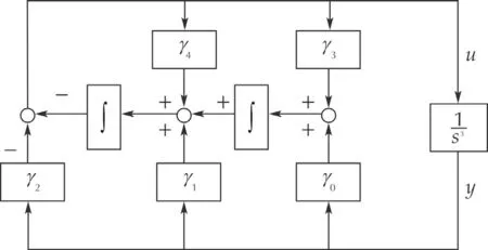
Fig.a1 GPIC stabilizing scheme,for a third-order system,using integral reconstructors.
Taking Laplace transforms in the last expression and after rearrangement it yields:

The characteristic polynomial of the closed-loop system is clearly given by

with freely assignable parameters for stability achievement.It is tedious but not difficult to show that the classical requirements for stable roots ofp(s)in equation(a7),imply,both,the stable locations of poles and zeroes of the filter in(a6).
In frequency domain terms,the integral reconstructorbased controller yields a dynamical classical compensation network of the form(a6).This subsystem can be regarded as a combination of a stable filter,smoothing the available output of the system,and a feed-forward term synthesizing the required plant input in terms of a linear combination of the internal states of such a filter.We address the above classical controller as theflat-filterbased controller.The reasons for this terminology are:1)Regarding the controller as a dynamical system with“input"represented by the output of the systemy,and with “output"represented by the system’s control input,u,the filtered outputyfqualifies as a flat output for such a linear dynamical system.Indeed,all variables in the dynamic compensator can be expressed in terms of the flat outputyfand a finite number of its time derivatives.2)A crucial property of flat linear time-invariant systems is that their transfer functions exhibit no zero dynamics.Such is the case of the transfer function of the filtered outputyfconsideringyas an input.The flat filtered output is defined as

The state space representation of the flat filtering controller follows immediately from the controller expression written in compensation network form and expressed back in the time domain.Defining,yf=ζ1and˙yf=ζ2,one has

A1.The robustness issue
Suppose it is desired to control the same system(a1)in a perturbed version of the form:

where ξ(t)is only known to be an absolutely bounded signal.A compensator would try to overcome the unknown disturbance with as many integrations in the compensator as reasonably possible in the hope offacing a classicaldisturbance of polynomial type.Notice,however,that any smooth,bounded,time-varying perturbation is ultra-locally efficiently approximated by a time polynomial of arbitrary degree(piecewise constant,piecewise linear,parabolic,etc.).Any finite degree time polynomial perturbation,taken as internal model of the unstructured additive perturbation,may then be also locally approximately cancelled by a sufficient number of differentiations.These differentiations are easily realized as iterated integrations in the denominator of the compensation network.
Recallthatin extended state observers and in GPIobservers,respectively,a single extra integrator,or,a finite number of integrations extending the observer’s state space,suffices to have an arbitrarily close estimation to the actual disturbance.Similarly,and dually,in GPIC based flat filters,the suitable addition of one or a finite number of integrators in the compensation network denominator will result,under closed-loop conditions,in at least the same number of time differentiations ofthe additive disturbance.This simple duality is atthe heartof regarding non-linear state dependent,and even input dependent,disturbances as unstructured time polynomialmodels[6]whose effects can be on-line identified[27],estimated[31],or cancelled,in an approximate manner.That this philosophy works even for nonlinear state and input dependent additive nonlinearities rests on the fact that,ultimately,while the system is operating on line,such disturbances are,indeed,time varying signals.Efforts to generally assess closed-loop stability of the existing control schemes adopting this modeling philosophy for disturbances may be found in[8,10,18,27,32].See also the excellent survey by Madonski and Herman[12].
The preceding paragraph justifies the use of a robust flat filter based compensator for the perturbed third-order pure integration system.Here a first degree time polynomial internal model is adopted for the additive perturbation(hence,m=2 is needed).A stabilizing task,to a trivial reference output equilibrium¯y=0,is imposed on the system.We propose then,

The closed-loop system evolves in accordance with

The disturbance,ultra-locally modeled(see Fliess and Join[27]and,also,[31])by a first degree time polynomial,is differentiated at least twice in the closed-loop system.




杂志排行
Control Theory and Technology的其它文章
- Active disturbance rejection control:between the formulation in time and the understanding in frequency
- Yet another tutorial of disturbance observer:robust stabilization and recovery of nominal performance
- Control of systems with sector-bounded nonlinearities:robust stability and command effort minimization by disturbance rejection
- On ADRC for non-minimum phase systems:canonical form selection and stability conditions
- Sampled-data extended state observer for uncertain nonlinear systems
- Extended state observer for uncertain lower triangular nonlinear systems subject to stochastic disturbance
