Numerical analysis of detaching and wrinkling of mechanically lined pipe during its spooling-on stage to the reel
2015-12-22TianfengZhaoZhihuiHu
Tianfeng Zhao∗,Zhihui Hu
aCollege of Mechanical and Transportation Engineering,China University of Petroleum,Beijing 102249,China
bEngineering Design Institute,CNPC Offshore Engineering Company Limited,Beijing 100028,China
Numerical analysis of detaching and wrinkling of mechanically lined pipe during its spooling-on stage to the reel
Tianfeng Zhaoa,∗,Zhihui Hub
aCollege of Mechanical and Transportation Engineering,China University of Petroleum,Beijing 102249,China
bEngineering Design Institute,CNPC Offshore Engineering Company Limited,Beijing 100028,China
H I G H L I G H T S
•Quasi 2D models simulating the gripping stresses preserved in the mechanically lined pipe(MLP).
•Critical spooling-on curvatures prediction for MLP liner-detaching.
•A comparative analysis for the liner wrinkling behaviors of MLPs with different wall thicknesses of outer layers.
A R T I C L E I N F O
Article history:
Accepted 31 August 2015
Available online 30 September 2015
Mechanically lined pipe
Detaching
Wrinkling
Spooling-on
Critical curvature
The structural behavior of mechanically lined pipes(MLPs)during the spooling-on phase is investigated in this paper,motivated by their promising offshore applications relying on reel installation.By applying quasi 2D models,we first investigated the gripping stresses preserved in the MLP after the hydraulic expansion manufacturing process and the detachment of the liner under spooling-on curvatures. Furthermore,a comparative 3D finite element(FE)analysis for the liner wrinkling behaviors of MLP with different wall thicknesses of outer layers was performed and indicated that when the wall thickness of outer layer increases from 14.3 mm to 17.9 mm,MLP’s critical spooling-on curvature increased more than 47%,reaching 0.1432 rad/m.
©2015 Published by Elsevier Ltd on behalf of The Chinese Society of Theoretical and Applied Mechanics. This is an open access article under the CC BY-NC-ND license(http://creativecommons.org/licenses/ by-nc-nd/4.0/).
1.Introduction
When compared against added-corrosion inhibitors for transportation,or laying submarine pipelines made of corrosion resistant alloys,mechanically lined pipes(MLPs)have obvious economic benefits for offshore exploitations in the strong corrosive environments found in oil and gas fields.MLP is a double-walled pipe,consisting of a load-bearing,high-strength,low-alloy carbon steel outer layer,lined with a thin-walled sleeve made from a corrosion-resistant material[1–3].However,due to high welding difficulty and low welding efficiency,a traditional s-lay approach requires a longer offshore operation time for the installation of MLP,which restricts the application ofthis type oftubularproduct. The industry believes that for MLP,the most efficient installation method is reel-laying,which requires welding and reeling on land, and then unwinding and installing on site at sea.
However,during the spooling-on phase,when MLPs are exposed to bending,the thin liner may start to detach and wrinkle, as indicated by full-scale tests[4,5],as well as finite element(FE) analyses performed by Hilberink et al.[6,7],Mair[8],Hilberink[9, 10],Yuan and Kyriakides[11]and some of the approximate analytical solutions in the works of Vedeld et al.[12]and Vasilikis and Karamanos[13].Vasilikis and Karamanos[13]used the FE model to study the elastic detachment of the liner in an MLP and gained considerable insight on wrinkling.
Subsea 7 and BUTTING had launched a joint research project on the feasibility and significant advantages of installing MLP using the reel-laying method[14].In MLP bending experiments implemented by Focke[5](Fig.1(a))and Hilberink [9](Fig.1(b)),a total of nine test strings is used to demonstrate that by applying internal pressure,a high quality lined pipe could be installed on the seabed fully fit-for-purpose with no formation of any wrinkles.
All studies mentioned above have indicated that to employ reel installation of MLP,the key is to solve the possible detaching, wrinkling,and collapsing of the liner layer during the spoolingon phase.Furthermore,the specific behavior of MLP during thereel-laying installation needs careful examination and testing to understand the influence of the global plastic deformation caused by bending on the mechanical contact between the liner and the outer layer,as well as the capacity on the liner to survive the reeling process without local buckling.Motivated by this challenge,significant efforts have been undertaken by industrial and academic researchers to establish the extent to which lined pipe can be safely bent,to identify the main factors that influence liner detaching or wrinkling,and also to find ways to prevent any deformation or detachment within the pipe.
This paper begins with modeling the gripping force of the MLPs, focusing on determining the critical curve,which causes liner detachment and wrinkling during the spooling-on phase.The postbuckling responses ofliner wrinkling are also investigated by 3DFE models in this paper,and we include a comparative analysis on the wall thickness influence of MLP’s outer layer.
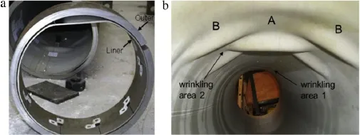
Fig.1.MLP bending experiments.(a)Liner detachment[5]and(b)wrinkled liner[9].
2.Initial stress states of MLPs
Several manufacturing techniques exist to produce MLPs. However,the most common technique employed is the hydraulic expansion method.During this manufacturing process,hydraulic pressure is applied to initiate plastic deformation ofthe liner;then, the pressure causes elastic deformation of the outer layer to seal the gap between the two pipe layers,which creates a rebounding and squeezing of the outside carrier pipe as it contracts.
During the hydraulic inflation process,the liner needs to be loaded and unloaded together with the outer layer;thus,elastic rebounding of the liner will always cause some loss of gripping force.In addition,because the outside carbon steel pipe cannot be deformed plastically in the manufacturing process,and the unloading of hydraulic inflation process is performed before the internal wall of carbon steel pipe begins to yield,a gripping force of MLPs exists.In this study,a typical MLP with geometric and material parameters similar to Focke’s studies are applied:(1)an outer layer made of X65 carbon steel(with outside diameter of 323.9 mm and wall thickness of 17.9 mm)and(2)a liner made of stainless steel Alloy 825(with outside diameter of 288.0 mm and wall thickness of 3 mm).
The real stress–plastic strain curves for X65 carbon steel and stainless steel Alloy 825 obtained from uniaxial tensile tests(as shown in Fig.2)are used for the quasi 2D FE model.For X65 carbon steel,the elastic modulus is 210 000 MPa,Poisson’s ratio is 0.3,and yield stress is 448 MPa,and for stainless steel Alloy 825 used for the liner,the elastic modulus is 193000 MPa,Poisson’s ratio is 0.3, and yield stress is 296 MPa.
FE methods are employed to simulate the gripping force induced in a hydraulic expansion-manufactured MLP.Four-node reduced-integration shell elements(S4R)are employed for the modeling of the thin-walled liner,whereas 8-node brick elements (C3D8R)are used to simulate the thick-walled outer layer.
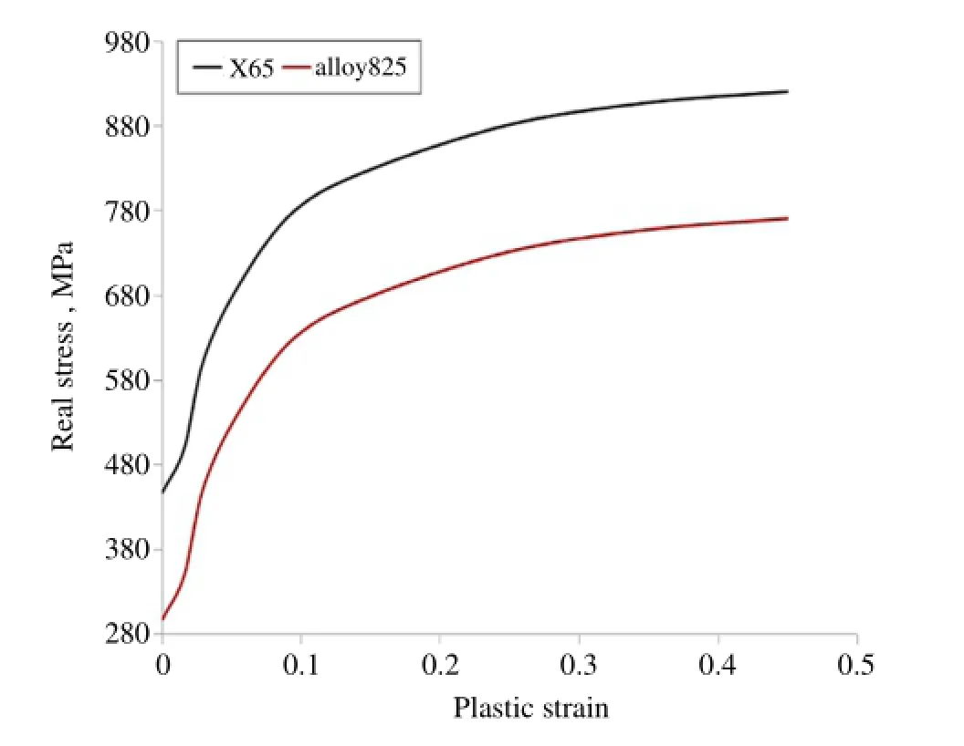
Fig.2.Real stress–plastic strain curves for the outer layer and liner materials.
Assuming no variation of loading and deformation in the longitudinal direction of the pipe,a quasi 2D model with normal hard contact between two pipe layers is adequate to model the hydraulic inflation process and estimate the gripping force between the two layers.A 0.1 m MLP segment is modeled to simulate the initial stress of the MLP and its detaching during the bending.
Through a loading–unloading analysis,the principal stresses of the outer layer and the liner induced by hydraulic expansion pressures(HEP)from 40 to 60 MPa can be acquired,as well as the final residual gripping stress(RGS)preserved in the layer interface of MLP,which are listed in Table 1.
For the liner,different HEP values bring almost the same unloading von Mises stress because of the plastic deformation of stainless steel Alloy 825 in the manufacturing process.Moreover, the liners are rarely influenced by HEP values after unloading the final principal stresses.For the outer layer of MLP,a higher HEP value means a greater internal wall stress of outer layer and a greater contact stress between two layers in the hydraulic expansion loading process.After unloading of HEP,the internal wallstresses ofouter layer and RGSes are approximate for different HEP values.
Therefore,increasing HEP is not an effective approach to enhance bonding strength of the MLP,which is highly dependent upon the mechanical properties of the liner itself.
3.Detachment of the liner when spooling an MLP onto a reel
Generally,the bending of the composite structure may lead to differential ovalization and eventual separation of part of the inner layer from the outer layer.The reeling process imposes high plasticstrains(due to bending)in the pipe,which may cause unacceptable liner detachment and wrinkling in MLP.
Herein,we discuss the possible detaching between the liner and outer layer and approach the problemnumerically,using nonlinear FEs to simulate liner’s deformation and its interaction with the outer layer.Stresses and strains are monitored throughout the deformation stage,detecting possible detachment ofthe liner from the outer layer.
C3D8R brick elements and S4R shell elements are employed to model the outer layer and the liner respectively.Bending moment was applied to a reference node coupling with one section of the outer layer when another section of the outer layer is constrained by a symmetry boundary condition.During the analysis the rotations of the reference node were recorded along with the bending moment applied.
Figures 3 and 4 demonstrate the contact opening contour between two pipe layers and the cumulative plastic strain contour of the outer layer at the detaching increment in the bending analysis followed the hydraulic inflation process,in which 50 MPa HEP is assumed and the RGS between pipe layers is 6.74 MPa.
Under elastoplastic conditions there is a nonlinear relationship between the reeling curvature of MLP and the bending moment loaded.As the reeling curvature increases the contact stress between the liner and the outer layer drops until the off-contact gap appears,which is shown in Fig.5.
When the reeling curvature of MLP reaches 0.117 rad/m at 6th increment,detaching appears followed by an increase of the reeling curvature and the off-contact gap of the detachment is enlarged.Figure 6 records the bending stress and cumulative plastic strain variation induced in the liner and outer layer during the reeling curvature increase process.
Figure 6 also indicates that together with the curvature growth in a reeling process,the bending stress and cumulative plastic strain of outer layer can rapidly increase,but those in the liner rarely change,most likely because the strain hardening has already begun from the hydraulic expansion process.
Generally,for a reeling-up process,the permitted cumulative plastic strain of the outer layer is 2.5%,which had already successfully serviced as a practical engineering standard in several Technip’s reel-laying projects;thus,the reel diameter is designed for such a requirement.FE analysis of this paper demonstrates that when the cumulative plastic strain of the outer layer of this test MLP reaches 2.5%,detachment already occurs,and liner wrinkling may also take place.

Table 1Stress analysis results for manufacturing process of MLPs.
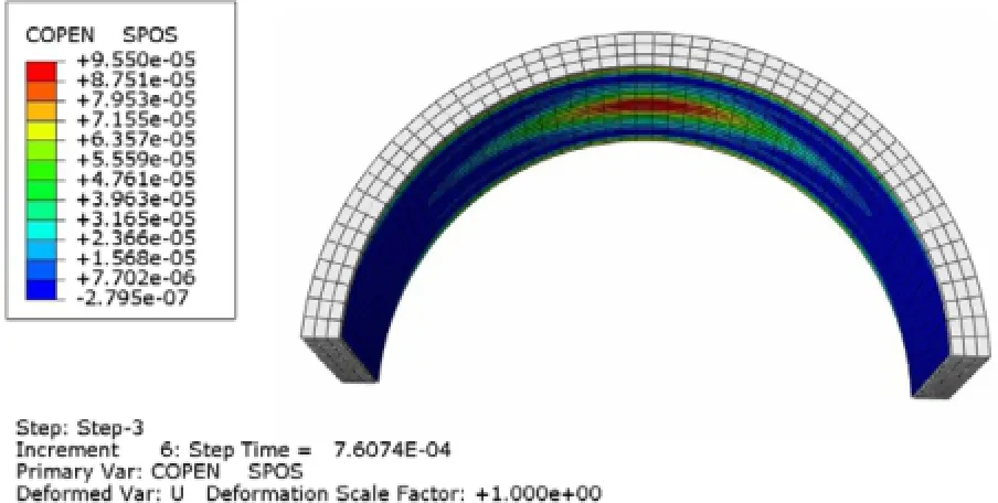
Fig.3.The contact opening between two pipe layers at the incrementofdetaching.
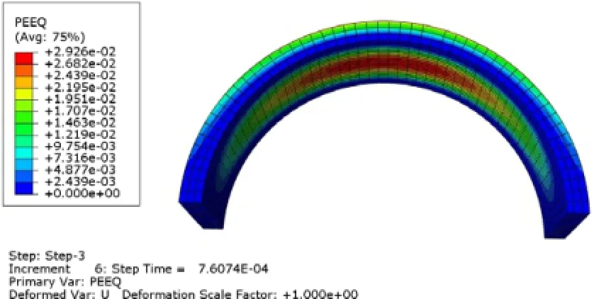
Fig.4.The cumulative plastic strain of the carrier pipe at the increment of the liner beginning detaching.
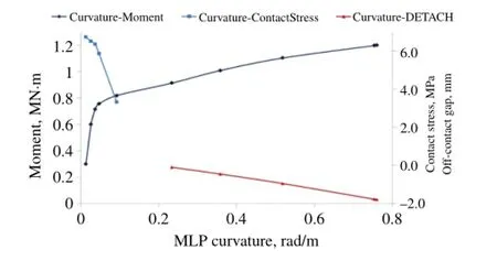
Fig.5.Bending moment,contact stress and off-contact gap in MLP as the reeling curvature of MLP increases.
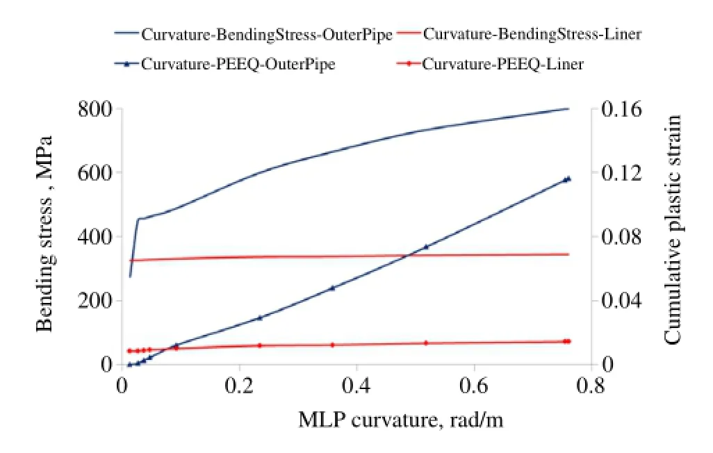
Fig.6.Bending stress and cumulative plastic strain induced in the liner and outer layer as the reeling curvature of MLP increases.

Fig.7.The contact stress distribution between two pipe layers of the test MLP when plastic strain upper limit of the outer layer reaches.
4.Winkling behavior of the liner when spooling an MLP onto a reel
A 3D FE model for the wrinkling behavior analysis was also developed utilizing C3D8R brick elements to model the outer layer and S4R shell elements to model the liner.Geometric and material parameters were same as those in the previous 3D model for detachment analysis,and a modified Riks algorithm was used to analyze the wrinkling response of MLP during the spooling-on stage of the MLP.
Herein,we discuss the scenario when spooling the MLP onto a reelin allorsubstantialabsence ofinternalpressure above ambient pressure in the MLP.As Riks analysis reached the 52th increment, the cumulated equivalent plastic strain in the outer layer of MLP reached 2.5%,which is the upper limit of plastic strain permitted by recent reeling-lay criteria(API spec 5 LD,2009 and DNV-OSF101,2010).This results in a permitted maximum MLP spoolingon curvature,called criticalspooling-on curvature,of0.1867 rad/m for the test MLP.We found that the liner already wrinkled with a cumulated equivalent plastic strain 3.61%.Figure 7 shows the contact stress distribution between the two pipe layers,in which corrugated detachment appears.For a spooling-on process before reel-laying operation,above liner detaching and wrinkling are also not permitted and these special requirements drop the critical spooling-on curvature of the test MLP to 0.1432 rad/m if no inner pressure is employed in the spooling-on process.
A comparative analysis is carried out when the wall thickness of the MLP outer layer changed to 14.3 mm and the outer diameter of 3 mm liner correspondingly increased,whereas other geometric and material parameters stayed the same.As Riks analysis reached the 19th increment,the cumulated equivalent plastic strain of the MLP out pipe already reached 2.6%,exceeding the upper limit of plastic strain.Thus,the analysis indicates that the spooling-on critical curvature of MLP with 14.3 mm wall thickness outer layer is less than 0.0974 rad/m.For this MLP,the critical spooling-on curvature decided by liner wrinkling is 0.1086 rad/m,so the final critical curvature can select 0.0974 rad/m.
For a comparative of the two MLP examples,Fig.8 provides relationship curves of the spooling-on curvature and the spoolingon bending moment.Figure 9 displays the wrinkling deformations and the final von Mises stress distributions of the liners under the 0.1867 rad/m spooling-on curvature.
5.Conclusions
1.The quasi-2DFE models have proven to be effective in modeling the manufacturing RGS or predicting the bending detachment of the MLP if plastic properties of bi-materials are fully taken into account.However,quasi-2D models are not sufficient enough to analyze the liner wrinkling behavior of MLPs for the possible different buckling modes.Thus,a 3D FE model is necessary.
2.Based on the hydraulic expansion manufacturing process, expansion pressure is not a sufficiently sensitive parameter in enhancing the final bonding force between the two layers of MLPs.The elastic rebound of the outer layer can only generate limited restriction on the liner,which needs to be assembled inside the outer layer before hydraulic expansion is performed. Thus,increasing RGS is not a feasible approach to make the MLPs reelable.In the bending process,the critical point of MLP rapidly loses RGS and begins detaching.
3.For a common pipeline to reel-laying,the critical spooling-on curvature means that the cumulated equivalent plastic strain reaches the upper limit(2.5%for most offshore criteria),but for an MLP,the criticalspooling-on curvature is the minimumvalue that may reach the upper-limit of plastic strain for the outer layer,liner detaching,or liner wrinkling.Taking the two 3D FE analyses as examples,MLP with outer layer of 17.9 mm wall thickness has a critical spooling-on curvature of 0.1432 rad/m, which depends on liner detaching and wrinkling.However,the same MLP with outer layer of 14.3 mm wall thickness has a critical spooling-on curvature of 0.0974 rad/m,which depends on the cumulated equivalent plastic strain of the outer layer.
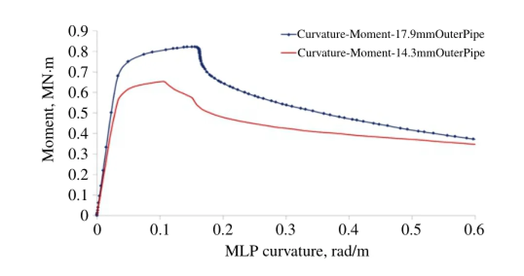
Fig.8.Relationship curves of MLP spooling-on curvature and spooling-on bending moment for test MLPs.
Acknowledgments
This study was supported by the Science Foundation of China University of Petroleum,Beijing(2462015YQ0415)and theSpecialized Research Fund for the Doctoral Program of Higher Education of China(20120007120002).
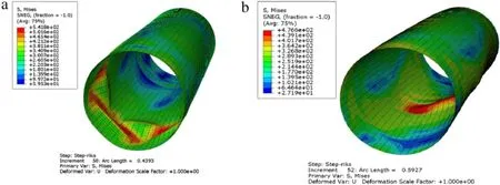
Fig.9.Different wrinkling deformations and von Mises stress distributions of the liners of two test MLPs under 0.1867 rad/m spooling-on curvature.(a)Test MLP with 14.3 mm outer layer.(b)Test MLP with 17.9 mm outer layer.
References
[1]I.Rommerskirchen,T.Schuller,K.Blachinger,et al.,New liner materials used in BuBi-pipes,in:Proc.Stainless Steel World,KCI Publishing B.V., ISBN:9073168201,2003,pp.49–53.
[2]A.C.De Koning,H.Nakasugi,P.Li,TFP and TFT back in town(Tight fit CRA lined pipe and tubing),in:Stainless Steel World,2003,pp.53–61.Jan./Feb.
[3]X.Wang,P.Li,R.Wang,Study on hydro-forming technology of manufacturing bimetallic CRA-lined pipe,Int.J.Mach.Tools&Manuf.45(2005)373–378.
[4]E.S.Focke,A.M.Gresnigt,J.Meek,et al.,The Influence of Heating of the Liner Pipe During the Manufacturing Process of Tight Fit Pipe,ISOPE,California, 2006.
[5]E.Focke,Reeling of tight fit pipe(Ph.D.thesis),University of Delft,2007.
[6]A.Hilberink,A.M.Gresnigt,L.J.Sluys,Liner wrinkling of lined pipe under compression:a numerical and experimental investigation,in:Proc.29th Int’l Conf.Ocean,Offshore&Arctic Eng.,OMAE2010-20285,Shanghai,June,2010. [7]A.Hilberink,A.M.Gresnigt,L.J.Sluys,Mechanical behaviour of lined pipe during bending:numerical and experimental results compared,in:Proc.30th Int’l Conf. Ocean, Offshore & Arctic Eng., OMAE2011-49434, Rotterdam,2011.
[8] J. Mair, Mechanical lined pipe—installationUnderwater Technology Conference, B e r g e n , June 2011.
[9]A.Hilberink,Mechanical behaviour of lined pipe(Ph.D.thesis),Delft Technical University, ISBN: 978-94-6186-012-5, 2011.
[10] A. Hilberink, Liner wrinkling in a lined pipe-a finite element approach, Explor. Prod. Oil Gas Rev. 8 (2012) 1 2 6 – 1 2 8 .
[11] L. Yuan, S. Kyriakides, Liner wrinkling and collapse of bi-material pipe under bending,Int.J.Solids Struct.51(2014)599–611.
[12]K.Vedeld,H.Osnes,O.Fyrileiv,Analytical expressions for stress distributions in lined pipes:axial stress and contact pressure interaction,Mar.Struct.26 (2012) 1 – 2 6 .
[13] D. Vasilikis, S.A. Karamanos, Mechanical behavior and wrinkling of lined pipes, Int.J.Solids Struct.49(2012)3432–3446.
[14]G.A.Toguyeni,J.Banse,Mechanically lined pipe:Installation by reel-lay,OTC 23096,in:Offshore Technology Conference held in,Houston,Texas,USA, 30 April-3 May, 2012.
23 August 2015
∗.
E-mail address:zhao_tianfeng@sohu.com(T.Zhao).
http://dx.doi.org/10.1016/j.taml.2015.08.004
2095-0349/©2015 Published by Elsevier Ltd on behalf of The Chinese Society of Theoretical and Applied Mechanics.This is an open access article under the CC BY-NC-ND license(http://creativecommons.org/licenses/by-nc-nd/4.0/).
*This article belongs to the Solid Mechanics
杂志排行
Theoretical & Applied Mechanics Letters的其它文章
- Direct comparison of hydraulic tortuosity and electric tortuosity based on finite element analysis
- Numerical investigation on the aerodynamics of a simplified high-speed train under crosswinds
- On the magnetic anomaly at Easter Island during the 2010 Chile tsunami
- Response of turbulent fluctuations to the periodic perturbations in a flow over a backward facing step
- Experimental study on interaction between a positive mass and a negative effective mass through a mass–spring system
- Understanding ductile-to-brittle transition of metallic glasses from shear transformation zone dilatation
