Output constrained IMC controllers in control systems of electromechanical actuators
2015-12-05PiotrMARUSAKSuwatKUNTANAPREEDA
Piotr M.MARUSAK,Suwat KUNTANAPREEDA
1.Institute of Control and Computation Engineering,Warsaw University of Technology,Nowowiejska 15/19,00-665 Warsaw,Poland;
2.Faculty of Engineering,King Mongkut’s University of Technology North Bangkok,Bangsue,Bangkok 10800,Thailand
Output constrained IMC controllers in control systems of electromechanical actuators
Piotr M.MARUSAK1,Suwat KUNTANAPREEDA2†
1.Institute of Control and Computation Engineering,Warsaw University of Technology,Nowowiejska 15/19,00-665 Warsaw,Poland;
2.Faculty of Engineering,King Mongkut’s University of Technology North Bangkok,Bangsue,Bangkok 10800,Thailand
Electromechanical actuators are widely used in many industrial applications.There are usually some constraints existing in a designed system.This paper proposes a simple method to design constrained controllers for electromechanical actuators.The controllers merge the ideas exploited in internal model control and model predictive control.They are designed using the standard control system structure with unity negative feedback.The structure of the controllers is relatively simple as well as the design process.The output constraint handling mechanism is based on prediction of the control plant behavior many time steps ahead.The mechanism increases control performance and safety of the control plant.The benefits offered by the proposed controllers have been demonstrated in real-life experiments carried out in control systems of two electromechanical actuators:a DC motor and an electro hydraulic actuator.
Constrained control,internal model control(IMC),model predictive control(MPC),electromechanical actuators
DOI10.1007/s11768-015-4047-0
1 Introduction
Internal model control(IMC)and model predictive control(MPC)are two well-established control tech-niquesused for years. The IMC has been developed until now and found applications in control systems of a wide spectrum of different control plants[1-6].The major advantages of the IMC include relatively simple form of the control law allowing applications with small sampling times,possibility to successfully apply this technique to control plants with difficult dynamics,and intuitive and easy-to-understand idea of the controller design.The design procedure applied in the paper consists in using the inverse of the zeroes and poles of the process model being inside the unit circle and then doing shaping of the dynamics of the controller.The shaping of dynamics can be done using the well-known pole placement or a heuristic technique.Thus,the controllers can be designed and tuned relatively easily.
In practice,there are always some constraints existing in control systems.If the constraints are not taken intoconsideration by the control algorithm,control performance can deteriorate.The MPC is a control technique in which it is relatively easy to take the constraints into consideration.It has been used in various applications due to the advantages it offers[7-11].The idea proposed in this paper makes use of the benefits of the IMC and MPC to obtain a simple,constrained control method for electromechanical actuators.
Electromechanical actuators are widely used in many industrial applications. Two electromechanical actuators are considered in this paper as illustrative examples.They are:a DC motor and an electro hydraulic linear actuator.DC motors are very popular actuators because of their simple structure and relatively low cost.They are also commonly used in the literature as illustrative control plants,allowing a reader to easily follow the proposed new ideas used in control systems of these plants[12-15].
electro hydraulic actuators are extensively used in the applications that need large action forces.They serve as very efficient actuators because they possess a high force-to-weight ratio,fast response,high stiffness,and high load capability.The applications that involve interaction with the environment might require force control.The electro hydraulic control is therefore an important field of research[16-21].
The idea behind the paper consists in extending the IMC controllers by combining them with an output constraint satisfaction mechanism adapted from analytical MPC algorithms.The output constraint handling mechanism is based on prediction of the control plant behaviour many time steps ahead.Moreover,as it is based on the mechanism adapted from analytical MPC algorithms,it does not need online optimization to be applied at each iteration(like in the numerical MPC algorithms),what allows the method to be used in control systems of fast control plants(with relatively small sampling times);see[18]for an application of the mechanism with the MPC analytical controller.
The rest of the paper is organized as follows.In the next section, the proposed controllers equipped with the mechanism of output constraint handling are described.In Section 3,descriptions of the experimental control plants are provided.Design of the controllers for the considered control plants is detailed in Section 4.Section5contains presentation of real-life experiments.The last section concludes the paper.
2 Constrained control design
This section proposes an approach for designing simple discrete-time controllers with efficient handling of output constraints.The control plant is assumed to be described by the following ARX model:

where y(k)is the output of the plant at time step k;k∈{0,1,2,...},u(k)is the input of the plant at time step k,d(k)is the disturbance at time step k,A(q-1)=1+a0q-1+a1q-2+...+an-1q-n,B(q-1)=(b0+b1q-1+b2q-2+...+bm-1q-m+1)q-1,and q-1is the delay operator.q-1f(k)=f(k-1),q-if(k)=f(k-i).
2.1 Control design
Assume that(1)can be expressed as

where Kprepresents the gain of the control plant,αs(q-1)=1+ αs1q-1+ αs2q-2+...has roots of A(q-1)placed inside the unit circle,αu(q-1)=1+ αu1q-1+αu2q-2+...contains the rest of the roots of A(q-1),βs(q-1)=1+ βs1q-1+ βs2q-2+...has roots of B(q-1)placed inside the unit circle,and βu(q-1)=(1+ βu1q-1+βu2q-2+...)q-1contains the rest of the roots of B(q-1).
Consider the IMC-based control structure shown in Fig.1[1],where r is the set-point signal,u is the control signal,y is the output of the control plant and˘y is the output of the control plant model.From(2),by neglecting the disturbance,the plant model can be written as


Fig.1 Structure of the control system with an IMC controller.

To design the IMC controller, polynomials αs(q-1)and βs(q-1)from(3)are exploited for pole-zero cancellation.Thus,the IMC controller is given by where the gain of the controller K and polynomials α0(q-1)and β0(q-1)are chosen by a designer.From(3)to(5),one obtains the following control law:

where αc(q-1)= α0(q-1)αu(q-1)-KKpβ0(q-1)βu(q-1),βc(q-1)= β0(q-1)αu(q-1).
Thus,the design process can be simplified and the dynamics of the controller can be chosen directly,in the standard unity feedback configuration.Instead of designing α0(q-1)and β0(q-1),polynomials αc(q-1)and βc(q-1)are directly chosen by the designer(their order and,at the same time,the number of the tuning parameters can be chosen according to the needs).It should be,however,noticed that the more complicated the polynomials αc(q-1)and βc(q-1)are,the more complicated the controller is,as well as its tuning and stability analysis.On the other hand,if one needs the controller with more degrees of freedom,then high-order polynomials can be used.One should however remember that the orders of these polynomials should be chosen in such a way that a causal controller is obtained.
2.2 Stability analysis
From(2)and(6),the closed-loop system without d(k)becomes

2.3 Output constraint handling
The control law(6)is derived based on the no-constraint assumption. Nonetheless in practice there are always some constraints existing in the control system.If the constraints are not taken into consideration by the control algorithm,control performance can deteriorate.In the case of simple controllers,in which obtaining of the control signal is not based on online optimization problem solving,control signal constraints can be taken into consideration using a mechanism of control projection onto the admissible set,as it is typically done in analytical MPC algorithms[8].
This mechanism can be used,after appropriate modification,for output constraint handling[18].The idea can be easily adapted to the discussed IMC controllers.The proposed mechanism is based on utilization of the control plant model to predict behavior of the control plant-the idea of prediction generation derived from MPC algorithms.As it will be shown in the latter part of the paper the mechanism can be used to improve operation and safety of control systems with the proposed controllers.Contrary to the method used in[18],here the output constraints will be transformed to the control values instead of control increments.Moreover,the simplified method of constraint transformation is presented,as in the case of IMC controllers(and also other controllers,for which the method can be applied),prediction will be used only in the constraint handling mechanism(not in the control law synthesis).Therefore,the disturbance used in the prediction can be just calculated(not transformed)and the predicted output values can be obtained recursively.As the result,less arithmetic operations are needed when the currently proposed method is applied.
According to(1)output of the plant model(with the neglected disturbance)in the next time step can be expressed as

where A0(q-1)=-a0-a1q-1-a2q-2-...-an-1q-n+1and B0(q-1)=b0+b1q-1+b2q-2+...+bmq-m+1.Thus,the 1-step ahead prediction of the output of the control plant at time step k can be expressed as

where dDMC(k)is a dynamic matrix control(DMC)-type disturbance added to the prediction in order to include influence of the disturbances and modeling uncertainty.The DMC is one of the MPC algorithms,based on the model in the form of step responses.In this algorithm it is assumed that the disturbance values d(k+i)in the future are equal to the current value of the disturbance d(k);see[8]for details.It is a reasonable assumption if one does not have a better estimate of these values.Thus,it is assumed in the proposed mechanism that dDMC(k)=d(k)since one does not have a better estimate of these values.
If needed,one can obtain the prediction recursively for many time steps ahead.Thus,the prediction of the output value for the(k+i)th step is described by
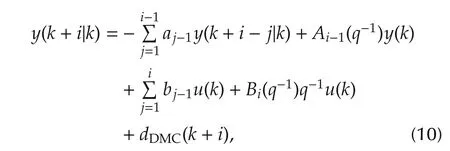
where Ai-1(q-1)=-ai-1-aiq-1-...-an-1q-n+iand Bi(q-1)= bi+bi+1q-1+...+bmq-m+i+1.If there is no estimation of future disturbances,it is assumed that dDMCis constant for all future time steps,thus dDMC(k+i)=dDMC(k).
The mechanism of output constraint satisfaction consists in constraining the control signal in such a way that the predicted output signal will not violate the constraint.Assume that the following constraint should be satisfied(lower bounds can be handled in a similar way):

where ymaxis the upper limit of the output variable.Thus,after using the prediction(9),the following constraint is obtained:

The constraint can be further transformed to the constraint put on the manipulated variable which was just calculated by the controller:

Now,it is sufficient to check if(13)is true,and if not,to modify the control signal;it is equivalent to apply the following rule:


The constraint for the ith time step is as follows:

which yields the following form:

Thus,the following control value modification rule is obtained:

A simulation study demonstrating the benefit of the present IMC algorithm equipped with the constraint handling mechanism compared with the operation of the online optimization-based MPC algorithm is given in the appendix.The latter algorithm is a standard one used in constrained control problems in the case when fast controller operation is not a critical issue(for relatively long sampling times).The results show that the characters of the responses obtained in both control systems are practically the same.However,the on line optimization-based algorithm is much more computationally expensive,which is not suited for implementation in the control systems considered in the paper.
3 Experimental control plants
3.1 DC motor
The first experimental control plant under consideration is a permanent magnet DC motor driving an inertial load through a gear train(see Fig.2).The control plant consists of a permanent magnet DC motor,a power amplifier,a gear train,a tachometer-generator,a potentiometer,a rotating mass which represents the inertia load,and a PC computer equipped with an ADC/DAC interface board.The speed of the motor is directly measured by the tachometer-generator.The potentiometer is used to measure the angular position of the load.The position and speed signals are fed back to the computer through the interface board.The control signal generated by the algorithm implemented on the computer is transmitted to the power amplifier.
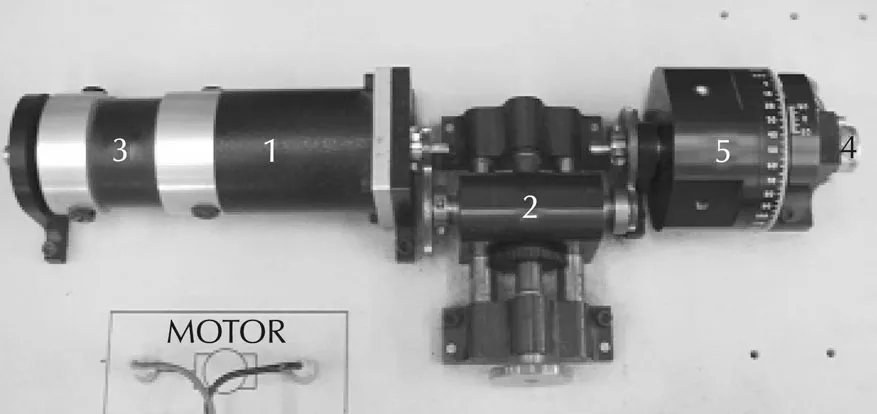
Fig.2 Experimental DC motor test bench.1:permanent magnet DC motor,2:gear train,3:tachometer-generator,4:potentiometer,and 5:inertia load.
The mathematical model of the motor can be simply expressed as[14]

where the speed of the rotor ω and the input voltage Vinare the plant’s output and input,respectively.Here,a=and
0c=The values of the parameters of the control plant are given in Table 1.

Table 1 Parameters of the DC motor.
3.2 electro hydraulic actuator
The next control plant under investigation is the electro hydraulic system shown in Fig.3.A force control problem is considered here.The system consists of a hydraulic power unit,a single-rod hydraulic cylinder,a servo solenoid valve,a loadcell,a spring which represents the environment or load,and a PC computer equipped with an ADC/DAC interface board.The cylinder is fixed on a frame.The environment or load’s force is applied to the end of the piston rod.The force is measured by the loadcell.The force signal is fed back to the computer through the interface board.The control signal generated by the algorithm implemented on the computer is transmitted to the servo solenoid valve.
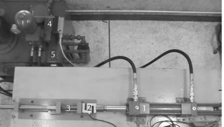
Fig.3 Experimental electro hydraulic test bench.1:hydraulic cylinder,2:loadcell,3:spring,4:servo solenoid valve,and 5:power unit.
The linearized model of the electro hydraulic system can be expressed as[16]

where the environment or load’s force F and the input u are the plant’s output and input,respectively.Here,u=is the input voltage,x is the displacement of the actuator,
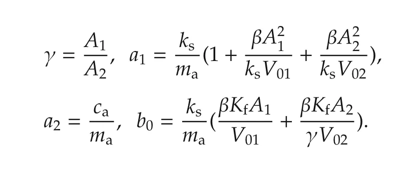
The values of the parameters of the control plant are given in Table 2.
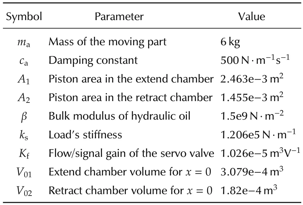
Table 2 Parameters of the electro hydraulic plant.
4 Design of controllers
4.1 DC motor
From(16),the transfer function is expressed as

After using the values of the parameters from Table 1 and discretizing P(s)with the sampling period of 0.005s,the ARX model of the control plant is as follows:

where y=ω,u=Vin,and d is the disturbance.Thus,it can be expressed in the form of(2)with Kp=1.202,αs(q-1)=1-0.8548q-1,βu(q-1)=q-1and αu(q-1)= βs(q-1)=1.From(6),the controller is assumed as

where K and α are tuning parameters.By choosing K=1/Kp,the closed-loop system is given as

Due to the simplicity of the closed-loop system,it is easy to notice that α<1 results in a stable control loop.
4.2 electro hydraulic actuator
From(17),the transfer function of the control plant can be expressed as

After using the values of the parameters from Table 2 and discretizing P(s)with the sampling period of 0.0001s,the following ARX model is obtained:

where y=F and d is the disturbance.Then,it can be expressed in the form of(2)with Kp=0.000652,αs(q-1)=1-1.914q-1+0.992q-2,αu(q-1)=1-q-1,βs(q-1)=1+0.2685q-1,andβu(q-1)=(1+3.7085q-1)q-1.
Thus,the controller given by(6)is as follows:

In the simplest controller(referred to as the first-order controller),the following polynomials are chosen:

Thus,in the first-order controller K and α are the tuning parameters.
Note that the first-order controller can be extended by adding the next first-order term as follows:

where α2is an additional tuning parameter.It can be generalized by choosing

where a and b are tuning parameters.This extended controller is referred in this paper as the second-order controller.
The stability of the control system with the first-order controller was tested using the Hurwitz criterion discrete-time systems. As a result, for the assumed range of values of α parameter(0<α<1),it was obtained thatfor gain K∈(0,413.57)nominal stability of the control system is guaranteed.
In the case of the discussed controllers the more complicated ones can be easily designed using the simpler ones.Such a procedure of the second-order controller design was found to be very useful during the real-life experiments.The details are given in Section 5.2.
5 Real-life experiments
5.1 DC motor
The proposed IMC speed controller,described in Section 4.1,with α =0.95 and ωmax=40 rad/s is used as a partofthepositioncontrolsystem.APIcontrollerisused as the position controller.The control system structure is shown in Fig.4.This control problem is widely found in practice.For example,in position control of some manipulators,the speed should be limited to avoid a risk of operation accident and to reduce the centrifugal force of the rotation joint caused by unbalanced masses.Also,a high speed operation can induce mechanical vibration in higher modes,which can cause instability.
The responses obtained in the control system of the DC motor with the speed controller designed in Section 4,equipped with the constraint handling mechanism,are shown in Fig.5.The control system is fast.The set-point value is achieved in half of the second.At the same time,the speed controller,thanks to the usage of the constraint handling mechanism,works in such a way that the maximum value of speed(ωmax=40rad/s)is practically not exceeded.Note that the speed constraint handling is implemented in the speed controller and works regardless the position controller used.

Fig.4 Position control system of the DC motor with the proposed constrained speed controller used in the inner control loop.
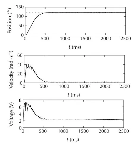
Fig.5 Responses of the control system of the DC motor with the constrained speed controller to the step change of the set-point value from¯θ=0°to¯θ=120°.
5.2 electro hydraulic plant
5.2.1 Tests of set-point signal following
During the first real-life experiment,responses of the first-order controller to the set-point change to¯F=800N and to periodic changes of the set-point signal were obtained.Here,K=1 and α=0.99 were chosen.The controller works fast and follows the sinusoid signal very well(see Fig.6).
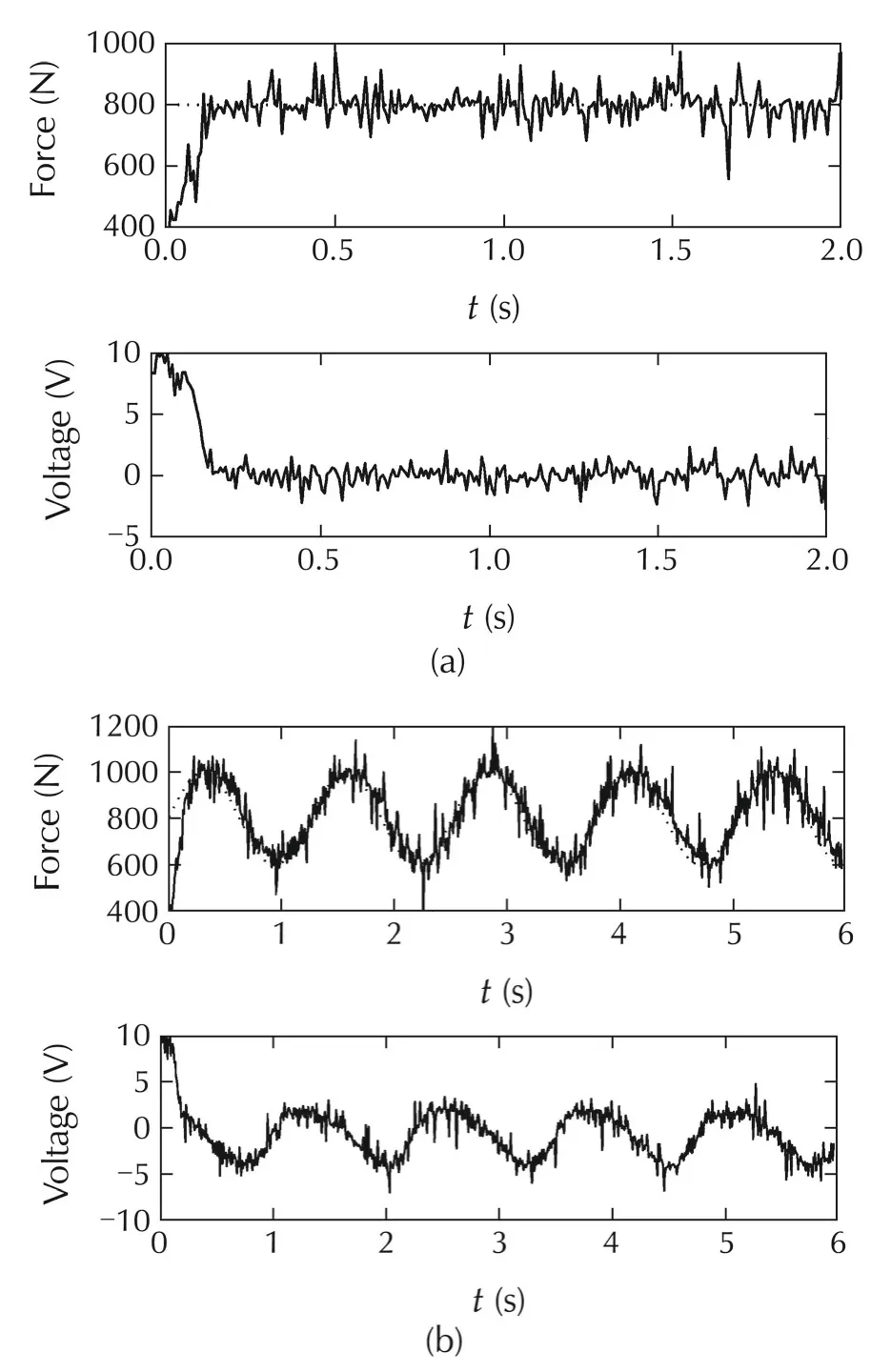
Fig.6 Responses of the control system of the electro hydraulic plant with the first-order controller to (a) the set-point signal from¯F=400N to¯F=800N and(b)the periodic changes of the set-point signal¯F(t)=800+200sin(5t)N.
Then,a heuristic method of the second-order controller design was used.The first-order controller was extended with the additional first-order term with α2=0.99.The second-order controller works as fast as the first-order one(see Fig.7).However,at the same time the obtained responses are smoother than in the previous experiment.Note that thanks to the form of the controller it is possible to gradually improve its operation,if needed.
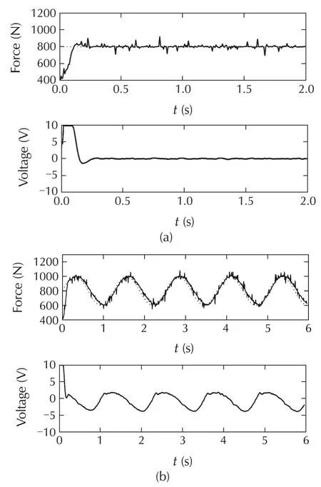
Fig.7 Responses of the control system of the electro hydraulic plant with the second-order controller to(a)the step change of the set-point signal from¯F=400N to¯F=800N and(b)the periodicchanges of the set-point signal¯F(t)=800+200sin(5t)N.
5.2.2 Tests of the output constraint handling mechanism
During the next experiments the output constraint handling mechanism was tested.The force limit is set to 1200N,assuming that it is introduced in order to prevent damage of a device the actuator interacts with.Responses to the periodic changes of the set-point signal,obtained with the first-order controller when only one predicted value of the output was constrained,are shown in Fig.8(a).Thanks to the application of the proposed mechanism,the output signal stays near the assumed limit(Fmax=1200N)instead of following the set-point signal.The mechanism works well despite its relative simplicity.
There was also done a test with different values of the constraint horizon(see Fig.8(b))in the control system with the second-order controller.In the case when only one future predicted output value was constrained the output signal is close to the constraint.For constraint horizon equal to 2,the output signal moves away the constraint.Thus,because of model ling uncertainty growing with the constraint horizon,more conservative control action is obtained(in terms of distance of the output signal from the constraint).However,it does not affect safety of the proposed approach;conversely,the risk of output constraint violation decreases.
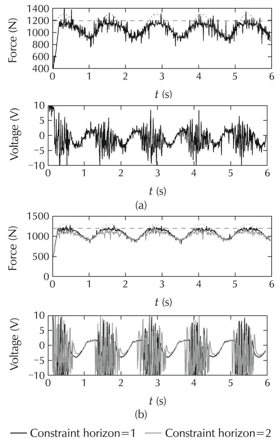
Fig.8 Responses of the control systems of the electro hydraulic plant(a)with the first-order controller and(b)with the second-order controller to periodic changes of the set-point signal¯F(t)=1100+200sin(5t)N.
6 Conclusions
The proposed constrained controllers,based on the well-established IMC and MPC techniques were successfully applied to the electromechanical actuators.The controllers offer good control performance and,at the same time,are relatively easy to design.
The output constraint handling mechanism can increase safety of the controlled process.It is,moreover,possible to constrain many future (predicted) output values what can positively influence effectiveness of the mechanism.Application details of the methods were discussed thoroughly,thus they can be easily applied to other control plants.
[1]M.Morari,E.Zafiriou.Robust Process Control.Englewood Cliffs:Prentice Hall,1989.
[2]W.Sun,J.Huang.On a robust synchronization problem via internal model approach.Asian Journal of Control,2010,12(1):103-109.
[3]Y.S.Lu.Internal model control of lightly damped systems subject to periodic exogenous signals.IEEE Transactions on Control System and Technology,2010,18(3):699-704.
[4]R.Dong,Y.Tan,D.He.Anonsmooth IMC method for mechanical systems with backlash.Journal of Control Theory and Applications,2013,11(4):600-607.
[5]D.Zhao,T.Chai.Intelligent optimal control system for ball mill grinding process.Journal of Control Theory and Applications,2013,11(3):454-462.
[6]T.Wang,W.S.Gan.Stochastic analysis of FXLMS-based internal model control feedback active noise control systems.Signal Processing,2014,101:121-133.
[7]E.F.Camacho,C.Bordons.Model Predictive Control.New York:Springer,1999.
[8]P.Tatjewski.Advanced Control of Industrial Processes:Structures and Algorithms.New York:Springer,2007.
[9]W.Chen,Y.Cao.Stability analysis of constrained nonlinear model predictive control with terminal weighting.Asian Journal of Control,2012,14(5):1374-1381.
[10]S.K.Kim,S.Y.Son,Y.Lee.Use of model predictive controller in dual-loop control of three-phase PWM AC/DC converter.International Journal of Control,Automation,and Systems,2014,12(2):340-348.
[11]E.Saade,D.E.Clough,A.W.Weimer.Model predictive control of a solar-thermal reactor.Solar Energy,2014,102:31-44.
[12]K.Nuri,R.Dhaouadi,N.B.Braiek.Adaptivecontrol of anonlinear DC motor drive using recurrent neural networks.Applied Soft Computing,2008,8(1):371-382.
[13]H.A.Yousef,M.E.Elkhatib,O.A.Sebakhy.Wavelet networkbased motion control of DC motors.Expert Systems with Applications,2009,37(2):1522-1527.
[14]J.Reyes-Reyes,C.M.Astorga-Zaragoza,M.Adam-Medina,et al.Bounded neuro-control position regulation for a geared DC motor.Engineering Applications of Artificial Intelligence,2010,23(8):1398-1407.
[15]R.Morales,J.A.Somolinos,H.Sira-Ram’ırez.Control of a DC motor using algebraic derivative estimation with real time experiments.Measurement,2014,47:401-417.
[16]P.Nakkarat,S.Kuntanapreeda.Observer-based backstepping force control of an electro hydraulic actuator.Control Engineering Practice,2009,17(8):895-902.
[17]M.H.Chiang.The velocity control of an electro-hydraulic displacement-controlled system using adaptive fuzzy controller with self-tuning fuzzy sliding mode compensation.Asian Journal of Control,2011,13(4):492-504.
[18]P.M.Marusak,S.Kuntanapreeda.Constrained model predictive force control of an electro hydraulic actuator.Control Engineering Practice,2011,19(1):62-73.
[19]M.Karpenko,N.Sepehri.electro hydraulic force control design of a hardware-in-the-loop load emulator using a nonlinear QFT technique.Control Engineering Practice,2012,20(6):598-609.
[20]T.Sangpet,S.Kuntanapreeda.Force control of an electro hydraulic actuator using a fractional-order controller.Asian Journal of Control,2013,15(3):764-772.
[21]C.Wang,Z.Jiao,S.Wu,et al.Nonlinear adaptive torque control of electro-hydraulic load system with external active motion disturbance.Mechatronics,2014,24(1):32-40.
Appendix
This appendix presents a simulation study demonstrating the benefit of the output constraint handling algorithm described in Section 2 compared with the operation of the on line optimization based MPC algorithm[7,8].The MPC algorithm was tunned to be as fast as the IMC algorithm;the assumed values of parameters are as follows: prediction horizon is equal to 400,and control horizon is equal to 1.The nonlinear model of the electro hydraulic actuator from Section 3.2 was used to simulate the control plant in the study.During example experiments,results of which are shown in Figs.a1 and a2,it was assumed that in the case of both algorithms constraint horizon is equal to 1.There are differences in the obtained responses but they are rather small.Both algorithms result in practically the same responses whereas the present algorithm consumes markedly less computational load,which is considered as its benefit over the numerical algorithm.Thus,it can be applied in the control systems which demand small sampling times.
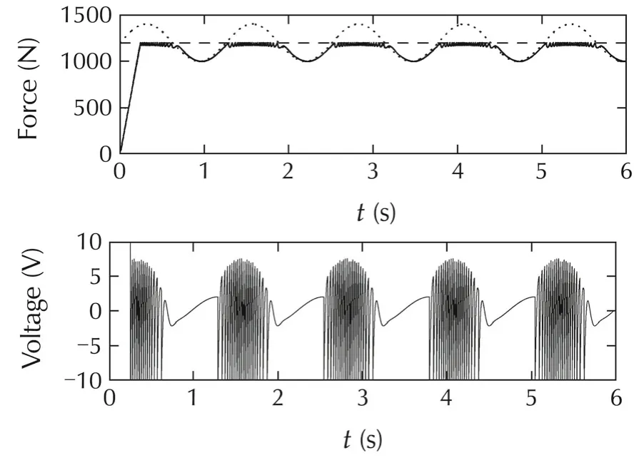
Fig.a1 Responses of the control system with the online optimization-based MPC algorithm;prediction horizon=400;constraint horizon=1.
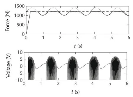
Fig.a2 Responses of the control system with the IMC controller with output constraint handling mechanism;constraint horizon=1.
There were also made experiments with both the MPC and IMC algorithms in different working conditions.First,it was tested,how the MPC algorithm behaves with different values of constraint horizon.It was found that when increasing the constraint horizon the MPC algorithm provides smoother control signal;see Fig.a3 for the responses obtained with constraint horizon equal to 400(the same as the prediction horizon which was used in the MPC algorithm).
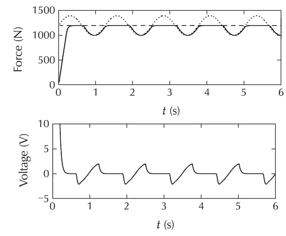
Fig.a3 Responses of the control system with the online optimization-based MPC algorithm;constraint horizon=400.
However,there were also made experiments with a random noise added to the output of the control plant(to better simulate the real-life conditions).Note that in the case of experiments described in[18]noise was present and must have been taken into consideration during design of the controller.In the case of constraint horizon equal to 400 the control system with the MPC algorithm behaved terribly(stabilized far from the set-point signal and far from the constraint).Its operation improved after reducing the constraint horizon.Thus,the problems were probably caused by too significant modeling uncertainty and demand to constrain the predicted output signal far in the future.The result obtained with the MPC algorithm for constraint horizon equal to 10 is shown in Fig.a4.Unfortunately,in the considered case control signal is non smooth,like in the case with too short constraint horizon,and without noise added to the output of the control plant.Moreover,there is also a high-frequency noise on the control variable.It can be also noticed that the output signal,due to some modeling inaccuracy,is a slightly below the constraint(has some safety margin).It is,in general,good behavior,but in the case of longer constraint horizon may result in inappropriate operation of the controller,what hap pend in the case when the constraint horizon was assumed equal to 400.
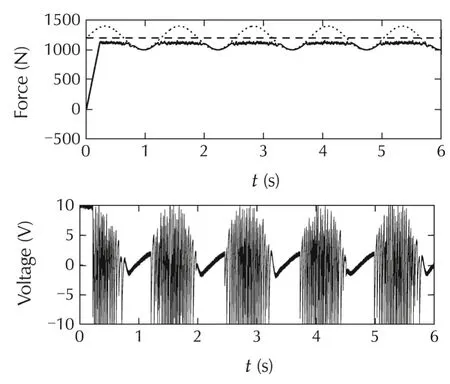
Fig.a4 Responses of the control system with the online optimization-based MPC algorithm;constraint horizon=10;a random disturbance added to the output of the control plant.
Similar experiment was done for the IMC algorithm with the proposed constraint handling mechanism(Fig.a5).This time the high-frequency noise is not present on the control variable and the output variable is less noisy.Thus,the IMC algorithm with the proposed constraint handling mechanism works better,in the considered case,than the MPC algorithm.It is also good to notice that the proposed mechanism with constraint horizon equal to 10(Fig.a5)gave practically the same result as when constraint horizon was equal to 400(Fig.a6),but it should be emphasized that in the latter case much more computations were needed.These experiments illustrate well the usefulness of possibility of choosing the constraint horizon in the proposed approach.
9 April 2014;revised 2 March 2015;accepted 3 March 2015
†Corresponding author.
E-mail:suwat@kmutnb.ac.th.Tel.:+66 2 555-2000;fax:+66 2 586-9541.
©2015 South China University of Technology,Academy of Mathematics and Systems Science,CAS,and Springer-Verlag Berlin Heidelberg
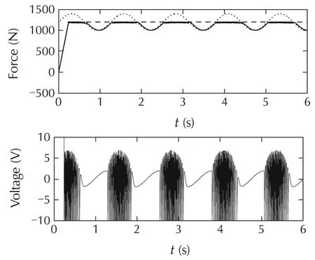
Fig.a5 Responses of the control system with the IMC controller with output constraint handling mechanism;constraint horizon=10;a random disturbance added to the output of the control plant.
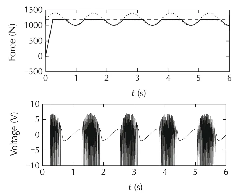
Fig.a6 Responses of the control system with the IMC controller with output constraint handling mechanism;constraint horizon=400;a random disturbance added to the output of the control plant.

Piotr M.MARUSAK received the M.Sc.degree in Computer Science and the Ph.D.degree in Automatic Control from the Warsaw University of Technology in 1997 and 2003,respectively.He is with the Institute of Control and Computation Engineering of the Warsaw University of Technology.His main research interests include predictive control algorithms based on linear and nonlinear(especially fuzzy)process models,as well as the application of these algorithms in fault-tolerant control systems,and the cooperation of predictive control algorithms with set-point optimization.E-mail:p.marusak@ia.pw.edu.pl.

Suwat KUNTANAPREEDA received the B.Eng.degree in Mechanical Engineering from King Mongkut’s University of Technology North Bangkok(KMUTNB),Thailand,in 1990,and the M.S.and Ph.D.degrees in Mechanical Engineering from Utah State University,U.S.A.,in 1992 and 1995,respectively.He is with the Department of Mechanical and Aerospace Engineering of KMUTNB.His research interests include nonlinear control,adaptive control,fractional-order control,intelligent control and applications of these control laws to mechatronic,chaotic,and aerospace systems.E-mail:suwat@kmutnb.ac.th.
杂志排行
Control Theory and Technology的其它文章
- Optimal control of quantum systems with SU(1,1)dynamical symmetry
- L1adaptive control with sliding-mode based adaptive law
- Infinite horizon indefinite stochastic linear quadratic control for discrete-time systems
- Error quantification of the normalized right graph symbol for an errors-in-variables system
- Quasi-Newton-type optimized iterative learning control for discrete linear time invariant systems
- On the use of positive feedback for improved torque control
