Ethernet based time synchronization for Raspberry Pi network improving network model verification for distributed active turbulent flow control
2015-12-05MarcelDUECKMarioSCHLOESSERStefanvanWAASENMichaelSCHIEK
Marcel DUECK ,Mario SCHLOESSER ,Stefan van WAASEN ,2,Michael SCHIEK
1.Central Institute of Engineering,Electronics and Analytics ZEA-2:Electronic Systems,Forschungszentrum Juelich GmbH,ZEA-2,Wilhelm-Johnen-Straβe,52428 Juelich,Germany
2.University of Duisburg-Essen,Faculty of Engineering,47057 Duisburg,Germany
Received 23 October 2014;revised 15 April 2015;accepted 20 April 2015
Ethernet based time synchronization for Raspberry Pi network improving network model verification for distributed active turbulent flow control
Marcel DUECK1†,Mario SCHLOESSER1,Stefan van WAASEN1,2,Michael SCHIEK1
1.Central Institute of Engineering,Electronics and Analytics ZEA-2:Electronic Systems,Forschungszentrum Juelich GmbH,ZEA-2,Wilhelm-Johnen-Straβe,52428 Juelich,Germany
2.University of Duisburg-Essen,Faculty of Engineering,47057 Duisburg,Germany
Received 23 October 2014;revised 15 April 2015;accepted 20 April 2015
Friction drag primarily determines the total drag of transport systems.A promising approach to reduce drag at high Reynolds numbers(>104)are active transversal surface waves in combination with passive methods like a riblet surface.For the application in transportation systems with large surfaces such as airplanes,ships or trains,a large scale distributed real-time actuator and sensor network is required.This network is responsible for providing connections between a global flow control and distributed actuators and sensors.For the development of this network we established at first a small scale network model based on Simulink and TrueTime.To determine timescales for network events on different package sizes we set up a Raspberry Pi based testbed as a physical representation of our first model.These timescales are reduced to time differences between the deterministic network events to verify the behavior of our model.Experimental results were improved by synchronizing the testbed with sufficient precision.With this approach we assure a link between the large scale model and the later constructed microcontroller based real-time actuator and sensor network for distributed active turbulent flow control.
Raspberry Pi,TrueTime,distributed actuator and sensor network,network model
DOI 10.1007/s11768-015-4143-1
1 Introduction
The FOR1779 group(“Active drag reduction by transversal surface waves”[1])deals with fundamental research concernig active drag reduction by transversal surface waves.The combination of this active method with passive riblet structures is investigated.
The described work deals with an enhancementof the model based development of a scale real-time actuator and sensor network for closed loop controlled transversal surface waves on an airfoil.The network model provides both,an interface for actuators and sensors which are meant for the realization of a closed loop wave control and an interface to the global closed loop flow control which is fed by a hot-wire sensor signal(see Fig.1).

Fig.1 Cascade control loop connecting external flow control with internal wave control by model in the loop network simulation.
The network simulation is intended to connect the actuation control[2]and the flow control(see Fig.1).Within this approach the network simulation can be either used as a single application for network investigations or model in the loop to connect the external flow control to the actuation control.This could for example be used for wind tunnel experiments.
Recently,we presented the use of a Raspberry Pi based testbed with a switched Ethernetnetwork connection[3].To improve the verification ofTrueTime network modelbehaviorwe now implemented an Ethernetbased timestamp synchronization with less overhead.This ensures sufficient precise results for time measurements on different network nodes.
In the following sections,the recent work which also represents the setup of our experiments will be described.Afterwards further investigations with the True-Time network-modelwillbe presented.Then the current synchronization approach for the Raspberry Pi testbed is highlighted.The last section will conclude the work and a brief overview of further issues will be given.
2 Recent work
A TrueTime simulation[4]was set up with a first communication paradigm.Fournodesrepresentthe network.Each type of node is used once.The later aim of a large scale actuator and sensor network is to use network nodes limited to these four types.Refering to the IEEE 1451 Smart Transducer Interface Standards[5]the nodes are named as follows:
.NCAPI:interfacing node;
.NCAPC:controlling node;
.STMA:actuating node;
.STMS:sensing node.
NCAP stands fornetwork capable application processor.STM is the smart transducer module,which should represent an NCAP with transducer interfacing module(TIM)as one node with a connection to digital or analog data excitation or aquisition devices.
Due to the idea of upscaling the network,the implemented communication sequence(see Fig.2)as well as the parameters which have to be introduced in every TrueTime simulation needed to be verified by a testbed.

Fig.2 Communication sequence of a package through the four nodes.Packages start nearly every 10 ms from STMS.The whole process runs for 10 s,so that there is an amount of about 4.000 communication-events per experiment.
Recent studies about gathering network parameters were done by Ionete et.al.[6]for package loss estimations.According to this approach a Raspberry Pi based testbed for the acquisition of transmission parameters was build.The communication behavior,which is used in the network model,was implemented into the testbed to establish a connection between the simulation and the real world.
In Table 1,the usage of a switched Ethernet approach is shown.All neccessary parameters needed in the True-Time simulation are listed[3].
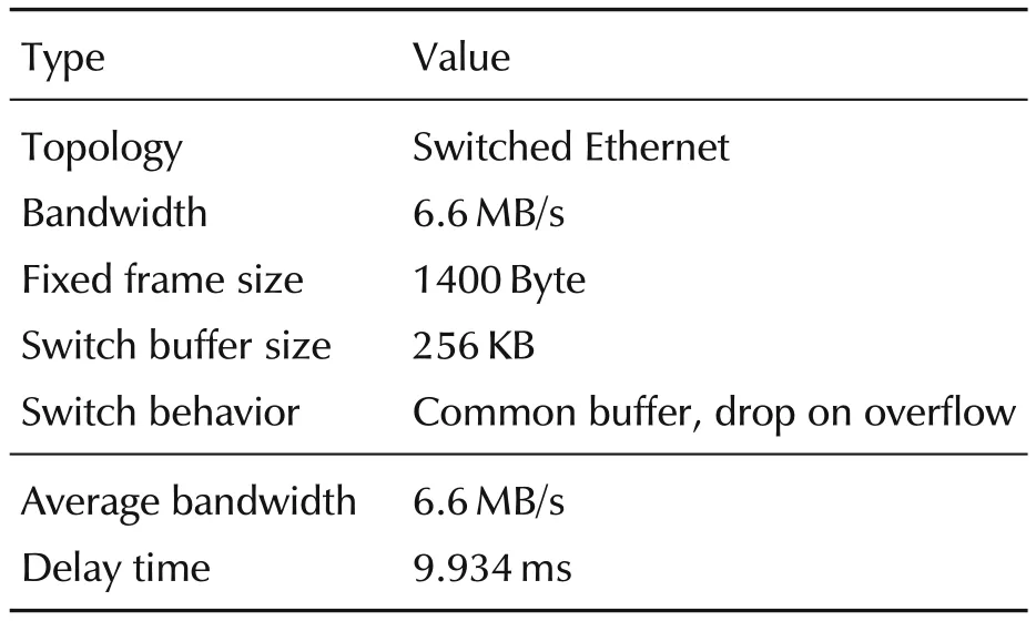
Table 1 Collected parameters introduced into the TrueTime model.
It was assumed that there are stochastical fluctuations in the testbed experiment which leads to a difference in time no matter what times are introduced into the model.This among other aspects,was investigated and is now presented in the next sections.
3 TrueTime network model
The proposed communication paradigm regarding the obtained parameters was extended.Three differentsizes of packages have been investigated,each was held constant during the simulation.
.64 Byte;
.732 Byte;
.1400 Byte.
The data generating node named STMS(sensornode),was modified by implementing a reduction of timing constants.Using different TrueTime code functions to generate a periodically executed function the simulation of this node could be characterized by just one single time segment.Instead of initiating a periodical task in the STMSnode a state machine was implemented.Likewise the other nodes have been modified.A good approach for the TrueTime modelling is the strict separation of source code and modifiable global constants.On the one hand some constants could be set by the graphicaluserinterface ofTrueTime blocks,on the other hand a global file which preserves the used time and package-size constants saves much time comparing different parameter configurations and makes automation much easier.
The documentation of the TrueTime toolbox states that the propagation delay is not considered in True-Time[7]nevertheless there is some delay induced when sending a package in the proposed switched Ethernet mode.The delay equals the propagation time,which is calculated by TrueTime,but in the resulting networkschedule there is no gap marked as busy.Considering the plain CSMA/CD Ethernet mode there is not any induced delay.The time schedules which mark the network as busy when we consider no time for calculation and forwarding fit together directly without any empty space in between.
Regarding the huge amount of work which is to be used for placing different nodes with predefined parameters onto a simulink sheet,a support tool has been written[3].The program with the purpose of“modelgeneration by GUI”is permanently growing during the development process of the network model.Fig.3 shows a result in the current configuration with automated generation of a network model.This corresponds to the described model together with the interfaces previously specified.In Fig.3 connected to NCAPIthere is an interface to communicate with the external flow control.Also in this figure STMAhas a connection to a model of an actuation system which can also be replaced by a network connection to the actuation control mentioned before[2].
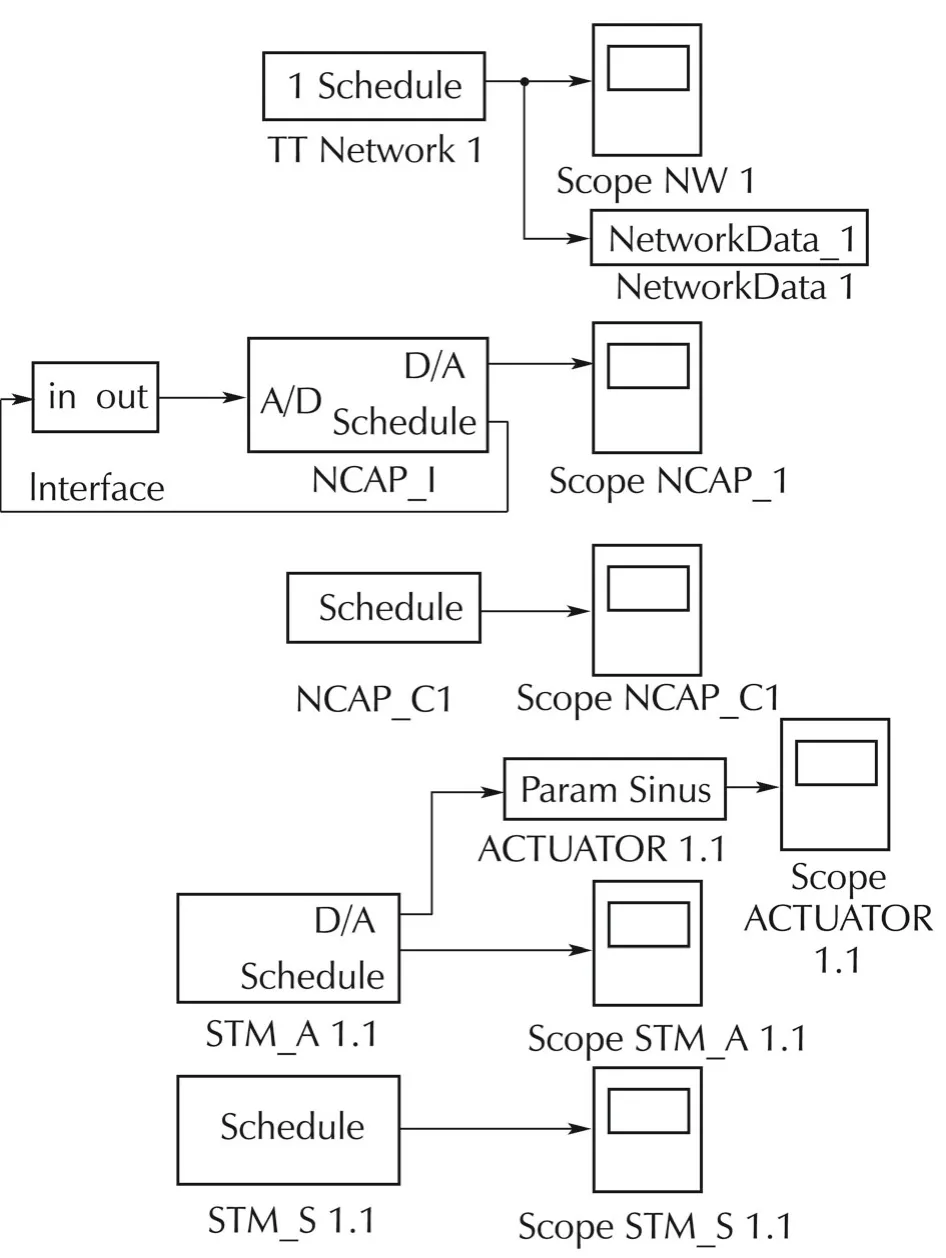
Fig.3 TrueTime model generated by an additional tool and extended with the proposed interfaces for global flow control and actuation control models.
4 Raspberry Pi testbed
4.1 Architecture comparison
About 20 years ago,the personal computer architecture became more and more important for the development of different applications and systems.For example for embedded applications it was well useable[8].Today there are low cost desktop computers with the well known architecture available.Computing power and storage seems not to be limited for current applications like CAD or high frequency data aquisition.Cost and size as well as energy consumption are main disadvantages to use personal computers for the purpose of a network communication testbed.
Other currently available platforms which could be used are microcontroller based embedded systems like the iNODE[9].Unfortunately the time and also the costs of hardware-development are very high,but advantages are the flexibility which provides a full adjustment to the requirements as well as low energy consumption and small size.These nodes run with real-time operating systems for this reason the preparation before implementation can start can be very time consuming and also debugging can be very complex.At this time,it is notneccessary to use something similarto the iNODE or the iNODE itself.Nowadays,the development of small and low cost computers is advancing rapidly.Computing power seems just to be limited by product size.The Raspberry Pi platform[10]is a good example for this,representing a small credit card sized computer limited in computation power and storage.Nevertheless,it has a very good cost-performance ratio and is easy configured for a direct start of implementation[11].In contrast to the pure microcontroller solution the Raspberry Pi also needs peripheral devices,at least a keyboard.Implementation is possible in common programming languages and results can be acquired quickly.In general,the Raspberry Pi is a good compromise between a pure microcontroller solution like the iNODE[9]and a standard desktop computer.In particular for our purpose it seems to be the best available solution.
4.2 Synchronization strategy
As proposed in the previous investigations[3]a more stable synchronization of the four Raspberry Pi nodes should produce more reliable results.The used mechanism of NTP in this scenario is not accurate enough.The proposed precision of 200μ s was not achieved[12].
Instead of integrating additional hardware like the real-time clock supposed recently[3]we now achieved synchronization by an Ethernet-broadcast in the network.It was implemented by an initial package without considering delays or network load.Different package sizes for the synchronizing-package show different accuracy.The smaller the package size,the more exact is the synchronization.If the package size grows also“impossible”results with difference in time between the nodes occur.
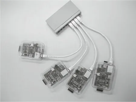
Fig.4 Raspberry Pi B nodes connected through a switched Ethernet network.The behavior of the nodes is monitored to estimate “real-world”network parameters.
The synchronization is initiated once at the start by STMA.Since the propagation delay is not included in this synchronization protocol it is not robust for use in busy networks,but a solution with less overhead for the investigated testbed.This protocol works properly for application in this small network and it is accurate enough for the current investigations.
Feasible ways of synchronization in a larger testbed or in the later application might be the IEEE 1588[13]which is related to the IEEE 1451 and developed at the same site or the synchronization by separated GPIOChannel which requires an additional wired connection between all nodes and might not be feasible.
The next section deals with the experiments made with the Raspberry Pi testbed and the comparison between measurements and simulation results.
5 Experimental results
About 70 experiments for each type of the three proposed package sizes were made.Within these experiments a cycle was executed every 10 ms.The experiment is started from STMAby sending the synchroniz-ing package.Then each cycle is initiated by the sensor node sending a package through controlling node,interface node,again controlling node and finally actuation node.

After this a sleep time of 9.75 ms was introduced.At first some experiments were made where the package size for the synchronizing package has the same size as the package size for sending the data packages frequently.Then this was compared to synchronizing by the smallest possible package(64 Byte)and better results occured.For the first part of measuring,every result of 1400 Byte was not useable and had to be withdrawn.
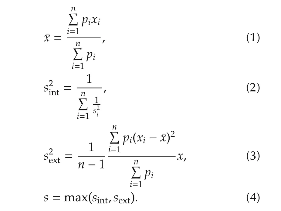
The useable results were analyzed by taking mean value and standard deviation of each simulation.For a better comparison between each package size the weighted mean value(equation(1))was taken,as well as the standard deviation which can be calculated by the maximum(equation(4))of internal(equation(2))and external(equation(3))consistency over all series of measurements[14].
Since the standard deviations(see Table 2)is not growing with package size and not stable between the directconsecutively occurring events on every node(Table 2,lines 1,2 and 4)there seems to be no direct relation between package size and standard deviation.In every of the three package size cases the time between these events is almost the same(e.g.,64 Byte:9.99 ms).If we try to compare our results directly with simulations working with the resulting mean time values there are several experiments where both are fitting nearly complete.This leads to the assumption that fluctuations between the measured events are rather a measurement error than a well characterising value for the data sets.
Considering the three different package sizes and the event rate there is a relation between decreasing number of events and growing mean time value.Therefore,the time between two events is depending on package size.If a simulation with different package sizes is considered,thishasto be taken into account.Then there has to be a calculation depending on the size of packages.
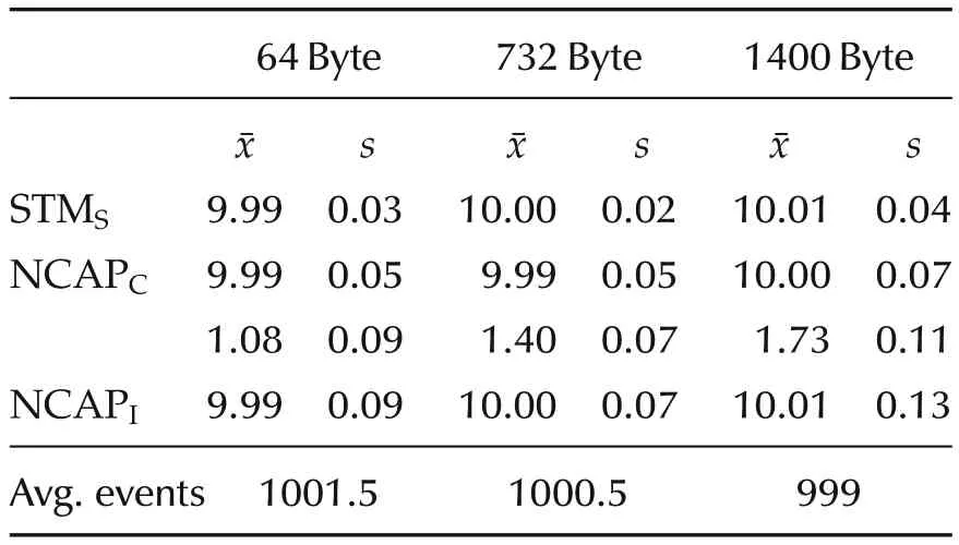
Table 2 Summarized characteristical values of the time measurements in ms,paired with the average events on STMS node in ten second lasting experiments.
Equation(5)delivers the approximationtstmsof waiting time between events regarding the results in Table 2.The size of the currently sent package is represented byp.The predefined values 64 as well as 9.99 representthe smallest size of a package and the shortest time which can be used in this experiment.

Considering the results of experiments with 732 Byte package size,network simulation data seem to be of good quality.The top line represents the STMS,the middle line represents NCAPCand the bottom line represents NCAPI.In the shown comparison(see Fig.5)the number of peaks is the same(e.g.,STMS1.000 peaks),so the differences between simulation and measurement are constant.
Taking a closeup into account(see Fig.6)the differences in time of the peaks on each node are in submillisecond region(less than 0.5 ms).This is the highest accuracy which can be obtained by using the configuration of measuring with the Raspberry Pi.
In the last section,the previously presented work is concluded and a brief outlook is given.
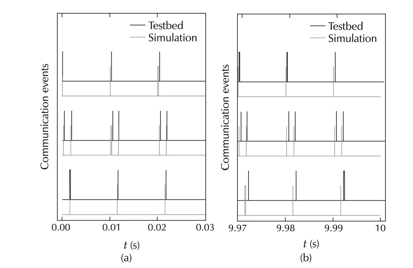
Fig.5 Result of a comparison between the Raspberry Pi based testbed and the TrueTime network simulation at 732 Byte package size with tstms=10.00 ms.The occurring communication events are compared by overlaying at(a)the beginning and(b)end of the experiment.
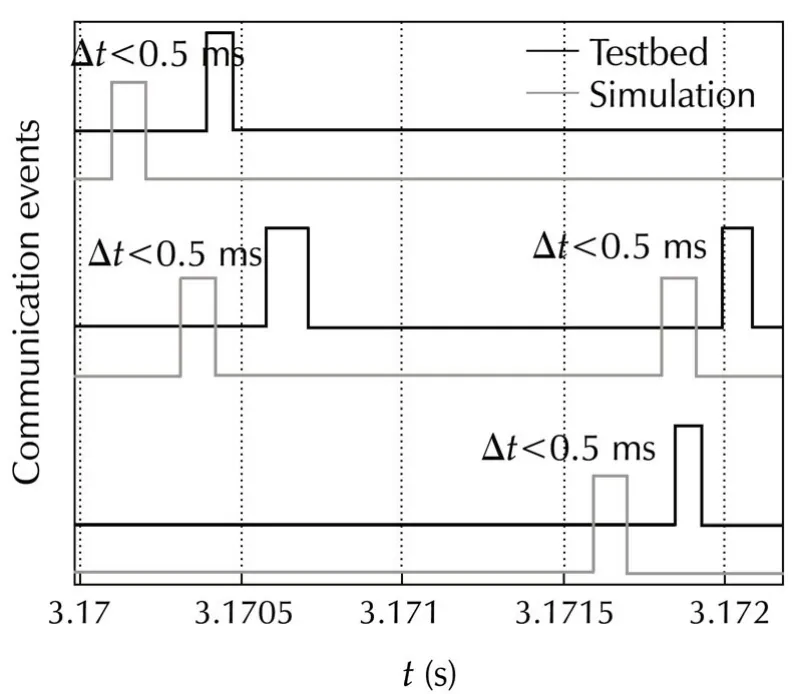
Fig.6 Closeup into comparison between the Raspberry Pi based testbed and the TrueTime network simulation.Difference between the results of measurement and simulation are in region of submilliseconds.
6 Discussion and outlo ok
In this paper,first the current situation in the development of a real-time actuator and sensor network for application in active turbulent flow control was presented.In the recent work,previous results and the communication paradigm were shown.Then the extension of the network model and simulation in TrueTime was explained.Concerning the linked testbed a brief overview of three different architectures was made with the result of Raspberry Pi as best solution available.We figured out that the Ethernet based broadcast synchronization works sufficiently and does not require additional hardware.Because propagation delay and network occupation is not considered in this approach,another strategy to synchronize all nodes in one network has to be considered.As main result from the experiments regarding the propagation time,the time between the sending events is depending on the package size.The assumption of a dependency between package size and standard deviation on estimated time differences could not be proved.
One of the next steps will be the implementation of state-machines into the model which fit to project requirements.This will go along with the connection of the project partners namely flow control and hardware development through a large scale network.
Considering such a large scale network it will also be interesting to use a testbed with more nodes.For the later application it could be useful to have a running testbed which is a small representation of the model where for example real-time signal processing algorithms could be investigated.
Particularly,the Raspberry Pi testbed could further be used to verify different types of synchronization algorithms.A first step will be the investigation of the IEEE 1588 Precision Clock Synchronization ProtocolStandard which is developed by NIST as well as the IEEE 1451 Smart Transducer Interface Standard[5,13].Regarding the wide range of literature concerning synchronization algorithms and strategies also other methods as IEEE 1588 should be taken into account.Hence,it should be possible to figure out which algorithm fits best to the proposed application with the future aim of usage in a microcontroller based large-scale actuator and sensor network.
Acknowledgements
The authors would like to thank all partners in the research group FOR1779.
[1]DFG.GEPRIS,2014:http://gepris.dfg.de/gepris/projekt/202175 528.
[2]M.Dueck,M.Kaparaki,S.Srivastava,et al.Development of a realtime actuation controlin a network-simulation framework for active drag reduction in turbulent flow.International Automatic Control Conference(CACS),New York:IEEE,2013,256–261.
[3]M.Dueck,M.Schloesser,M.Kaparaki,et al.Raspberry Pi based testbed verifying truetime network model parameters for application in distributed active turbulent flow control.Proceedings of SICE Annual Conference.New York:IEEE,2014:1970–1975.
[4]A.Cervin,D.Henriksson,B.Lincoln,et al.How does control timing affect performance?Analysis and simulation of timing using jitterbug and truetime.IEEE Control Systems Magazine,2003,23(3):16–30.
[5]IEEE Standard for A Smart Transducer Interface for Sensors and Actuators–Network Capable Application Processor(NCAP)Information Model.New York:The Institute of Electrical and Electronics Engineers,2000.
[6]C.Ionete,D.Sendrescu,D.Popescu,etal.Ethernetfornetworked control an experimental test bench.Proceedings of the 49th Annual Conference of the Society of Instrument and Control Engineers of Japan,Piscataway:IEEE,2010:3556–3559.
[7]A.Cervin,D.Henriksson,M.Ohlin.TrueTime 2.0 Beta–Reference Manual.Sweden:Department of Automatic Control,Lund University,2010.
[8]R.Lehrbaum.Using the PC architecture in embedded applications.Proceedings of WESCON.New York:IEEE,1993:610–620.
[9]M.Schloesser,A.Schnitzer,Y.Hong,et al.iNODE:intelligent network operating device forneurologicaland neurophysiological research.Proceedings of the 4th European Conference of the International Federation for Medical and Biological Engineering.New York:Springer,2009:1710–1713.
[10]The Raspberry Pi Foundation.FAQs of Raspberry PI.2014:http://www.raspberrypi.org/faqs.
[11]S.Banerjee,D.Sethia,T.Mittal,et al.Secure sensor node with Raspberry PI.International Conference on Multimedia,Signal Processing and Communication Technologies.New York:IEEE,2013:26–30.
[12]Network Time Foundation.The Network Time Protocol.2014:http://www.ntp.org/.
[13]IEEE Std 1588-2008:Standard for a Precision Clock Synchronization Protocol for Networked Measurement and Control Systems.New York:The Institute of Electrical and Electronics Engineers,2008.
[14]H.Gr¨anicher.Messung beendet-was nun?:Einf¨uhrung und Nachschlagewerk f¨ur die Planung und Auswertung von Messungen.Stuttgart:vdf,Hochsch.-Verlag an der ETH Z¨urich,1996.

the B.Sc.in Scientific Programming from Aachen University of Applied Sciences,Aachen,Germany,and a degree as mathematicaltechnicalsoftware developer(MaTSE)from the Chamber of Commerce(IHK,Aachen)in 2010.In 2012,he
the M.Sc.in Technomathematics“Integration of mobile iOS devices in instrumentation applications”from Aachen University of Applied Sciences,Aachen,Germany.He is a Ph.D.candidate at the RWTH Aachen University,Aachen,Germany,and working as Research Associate in the Central Institute of Engineering,Electronics and Analytics,Systems of Electronics,Forschungszentrum J¨ulich,Germany.His research interest covers distributed large scale real-time actuatorand sensornetworks and iterative learning controlalgorithms.E-mail:m.dueck@fz-juelich.de.

Mario SCHLOESSERreceived the Diploma in Electricaland Computer Engineering from Aachen University of Applied Sciences,Aachen,Germany,in 2006.He has seven years of Ramp;D experience as Development Engineerin the CentralInstitute ofEngineering,Electronics and Analytics,Systems of Electronics,Forschungszentrum J¨ulich,Germany.Since 2014,he is appointed as Head of the Digital Hardware Systems Department.His current research interests include the miniaturization of distributed sensor and actuator networks,high speed communication protocols and embedded DAQ systems.E-mail:m.schloesser@fz-juelich.de.

Stefan van WAASENreceived his Diploma as well as Doctor’s degree in Electrical Engineering from Duisburg University,Germany in 1994 and 1999,respectively.He has 13 years experience in industrial development of semiconductor based wireless and wireline communication products.Since 2010,he is Directorofthe CentralInstitute ofEngineering,Electronic and Analytics:Electronic Systems at Forschungszentrum J¨ulich.Since 2014,he is also Professor for Measurement and Sensor Systems at University of Duisburg-Essen at the Faculty of Engineering.His current reasearch interests are complex detector systems and high integration strategies.E-mail:s.van.waasen@fz-juelich.de.

Michael SCHIEKreceived the Diploma degree in Physics in 1994 and the Ph.D.degree in 1998 both from the RWTH Aachen University,Aachen,Germany.Since 1998,he has been Scientific Assistant at the Research Centre J¨ulich,Central Institute ZEA-2 Electronic Systems,Germany,where he is heading ofthe team “Modelling and Algorithms”.His current research interests include nonlinear time series analysis and distributed sensor-actuator networks.E-mail:m.schiek@fz-juelich.de.
†Corresponding author.
E-mail:m.dueck@fz-juelich.de.Tel.:+49 2461-61 5267.
This work was supported by German Research Foundation(DFG)(No.1779-WA3076/1-1).
©2015 South China University of Technology,Academy of Mathematics and Systems Science,CAS,and Springer-Verlag Berlin Heidelberg
杂志排行
Control Theory and Technology的其它文章
- Distributed dynamic pricing based on demand-supply balance and voltage phase difference in power grid
- Decentralized load frequency control for two-area interconnected power system
- Increasing the operating area of shunt active filters by advanced nonlinear control
- Simple adaptive air-fuel ratio control of a port injection SI engine with a cylinder pressure sensor
- Estimation and feedback control of air-fuel ratio for gasoline engines
- Gain-scheduling control of a floating offshore wind turbine above rated wind speed
