Gain-scheduling control of a floating offshore wind turbine above rated wind speed
2015-12-05OmidBAGHERIEHRyozoNAGAMUNE
Omid BAGHERIEH ,Ryozo NAGAMUNE
1.Department of Mechanical Engineering,University of California at Berkeley,5146 Etcheverry Hall,Berkeley,CA 94720,U.S.A.;
2.Department of Mechanical Engineering,University of British Columbia,6250 Applied Science Lane,Vancouver,BC V6T1Z4,Canada
Received 30 October 2014;revised 25 April 2015;accepted 27 April 2015
Gain-scheduling control of a floating offshore wind turbine above rated wind speed
Omid BAGHERIEH1,Ryozo NAGAMUNE2†
1.Department of Mechanical Engineering,University of California at Berkeley,5146 Etcheverry Hall,Berkeley,CA 94720,U.S.A.;
2.Department of Mechanical Engineering,University of British Columbia,6250 Applied Science Lane,Vancouver,BC V6T1Z4,Canada
Received 30 October 2014;revised 25 April 2015;accepted 27 April 2015
This paper presents an application of gain-scheduling(GS)control techniques to a floating offshore wind turbine on a barge platform for above rated wind speed cases.Special emphasis is placed on the dynamics variation of the wind turbine system caused by plant nonlinearity with respect to wind speed.The turbine system with the dynamics variation is represented by a linear parameter-varying(LPV)model,which is derived by interpolating linearized models at various operating wind speeds.To achieve control objectives of regulating power capture and minimizing platform motions,both linear quadratic regulator(LQR)GS and LPV GS controller design techniques are explored.The designed controllers are evaluated in simulations with the NREL 5 MW wind turbine model,and compared with the baseline proportional-integral(PI)GS controller and non-GS controllers.The simulation results demonstrate the performance superiority of LQR GS and LPV GS controllers,as well as the performance trade-off between power regulation and platform movement reduction.
Wind energy,gain-scheduling control,linear parameter-varying model,floating offshore wind turbines,above rated wind speed,power capture,platform motion
DOI 10.1007/s11768-015-4152-0
1 Introduction
Offshore wind turbines that are installed on a platfrom floating on the deep-water sea are becoming more and more popular worldwide due to their potential advantages of large and consistent power capture as well as small environmental impacts[1–3].However,the energy cost of floating offshore wind turbines is typically much higher than onshore ones and offshore ones with fixed foundations,and thus needs to be reduced fortheir further prevalence.Modeling and control of floating offshore wind turbines are of great importance for such cost reduction[4].
As for the modeling,a high-fidelity nonlinear modelfor floating offshore wind turbines has been developed in[5],and implemented in software FAST[6].This software is capable of not only running simulations using the nonlinear model,but also acquiring numerically the linearized model of the turbine under each operating condition.To cover some potential drawback of FAST,a control-oriented model of offshore wind turbines was derived in[7]and proven to behave similarly to the FAST model.An overview of offshore wind turbine modelling was presented in[8].
The linearized models obtained in these papers are only accurate around a selected operating condition.However,when the operating condition varies during the operation of wind turbines,the wind turbine dynamics will change accordingly,and therefore,it is appropriate to design a controller based on a model which represents dynamics variations explicitly.For the purpose of expressing dynamics variations,linear parametervarying(LPV)models for onshore and offshore wind turbines were developed in[9]and[10],respectively.However,these LPV models deal with only the blade rotation angle as the varying parameter,and does not incorporate other parameters which may change,such as wind speed and blade pitch angle.
As far as control of floating offshore wind turbines above rated wind speed,called Region III,is concerned,various blade pitch control methods were worked out such as state feedback,loop shaping and model predictive control[11–14].Additionally,in[10,15],linear time-invariant controllers were designed based on the LPV modeloffloating offshore wind turbines.These controllers,however,do not address plant dynamics variation with respect to wind speed variation.Moreover,a PI gain-scheduling(GS)controller which deals with the plant dynamics variation was proposed as a baseline controller in[16].However,the PI GS controller may encounter some performance limitations,because they have only a few tuning parameters.Blade pitch controllers with higher complexity will have potentials for performance improvement in Region III.
In this paper,LQR GS and LPV GS blade pitch controllers in Region III are designed for a floating offshore wind turbine on a barge platform.For LPV controller design,an LPV model is obtained by FAST linearization and an interpolation technique.The designed controllers are compared in simulations using FAST nonlinear model with the baseline PI gain-scheduling controller and linear time-invariant LQR controllers.It is verified by simulations that LQR GS and LPV GS controllers can improve both power regulation and platform motion reduction compared to the baseline controller,and that GS controllers outperform linear time-invariant ones.Furthermore,simulation results demonstrate that state feedback LQR GS offers much better performance than output feedback LQR GS does,which indicates the importance of platform motion sensors.
2 Plant description and control objectives
2.1 A floating offshore wind turbine
In this paper,we dealwith an offshore wind turbine attached to the buoyancy stabilized platform,which is also called barge platform(see[16]forotherfloating platform types).The barge platform is cheaper compared to other platforms.However,since a part of the barge platform is above sea level,waves can induce large motions of the platform.These motions will cause fatigue loads in the structure and components of the turbine,as well as the reduction in the captured energy.
The overall structure of a wind turbine and its platform degrees of freedom are illustrated in Fig.1.The wind passes through the rotational plane of the blades.The interaction between the blades and wind produces lift force,which rotates the blades.This rotation is transmitted to the generator via a gearbox.
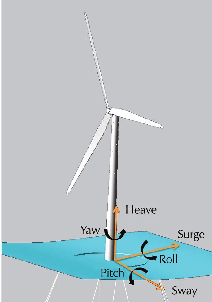
Fig.1 An illustration of a floating offshore wind turbine system and its platform degrees of freedom.
A wind turbine has three kinds of control inputs,i.e.,generator torque,blade pitch angles and nacelle yaw angle.Both generator torque and blade pitch angles are used to control the rotational speed of the shaft and the power capture.The three blades used in a wind turbine can be controlled individually or together which are called individual blade pitch and collective blade pitch control,respectively.To design a less complex controller,we will use the collective blade pitch method.For offshore wind turbines,blade pitch angles can also affect the platform motions.On the other hand,the actuator for the nacelle yaw angle is used in order to face the turbine in the direction of wind.Here,it is assumed thatthe wind direction is notchanging,and the turbine is always facing the wind direction.Therefore,nacelle yaw angle actuator is not used for this work.In summary,in this paper,generator torque and collective blade pitch angle are utilized as control inputs.
2.2 Operating regions of wind turbines
Fig.2 illustrates an example of the operating region for a specific wind turbine considered in[16]and in this paper.The available energy in wind and also the energy which should be captured by the turbine are shown in the figure.
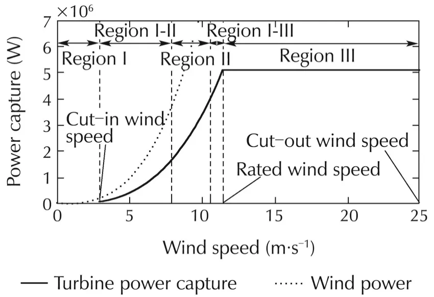
Fig.2 The power curve.
The rated wind speed is the lowest wind speed at which the rated power of a turbine is produced.This wind speed divides the operating region of a wind turbine into low wind speed region(Region II)and high wind speed region(Region III).Region III for the specific turbine considered in[16]and in this paper is given by{v:11.4≤v≤25}where v(m/s)denotes wind speed.
2.3 Control objectives for Region III
In Region III,the power which can be captured by the turbine is more than the rated power of the generator.Therefore,we need to regulate power capture at the rated power.Moreover,reduction ofplatform movements is anotherimportantcontrolobjective,to mitigate structural loading and power loss.
The captured power,denoted by P W,is obtained using the following equation:

where Tg(N·m)is the generator torque,ωg(rad·s−1)is the generator speed,and η is the generator efficiency.
There are two standard methodsto regulate the power capture to the rated power Pratedusing(1):
.Fixing Tgto the rated torque Trated,and regulating ωgto the rated generator speed ωg,ratedby manipulating blade pitch angle β.
.Regulating P to the rated power Pratedby manipulating Tgand β simultaneously.
The first method simplifies the controller and reduces loads on the turbine,but increases power fluctuations.The second method regulates power more effectively,but adds complexity to the controller and increases loads on the turbine[13].In this paper,to make the controller less complex and to reduce turbine loads,the first method is adopted.To regulate generator speed in the first method,the aerodynamic torque applied by the wind must be adjusted,because the generator torque is fixed.The aerodynamic torque can be controlled by modifying blade pitch angle in order to compensate for the variation in wind speed.
For minimization of platform movements,in this paper,we take into account only pitch movement ypptfor controller design,because the pitch motion will be most significant under the situation when the wind turbine is facing to the wind direction[13,14].
To recap,the control objectives for Region III are to minimize the deviation ofωgfromωg,ratedand the amplitude of ypptover the operating period by manipulating blade pitch angle.
3 LPV modeling for controller design
In this section,a method to derive an LPV model numerically for offshore floating wind turbines is presented,by using the software FAST.The model is to be used in Section 4 for LPV controller design.This section first reviews a nonlinear model realized in FAST briefly,and then presents a method for the LPV modelling from linearized models at various operating conditions of the nonlinear model.The LPV modelling method is applied to a specific wind turbine,Offshore NREL 5 MW Baseline Wind Turbine,which is a combination of the Onshore NREL 5 MW Baseline Wind Turbine and the ITI Energy Barge Platform[16].This turbine is referred to as NREL 5 MW.
3.1 Nonlinear model
The nonlinear model of an offshore wind turbine realized in FAST is represented in a state-space form as

Here,the control input vector u consists of generator torque,blade pitch angle and nacelle yaw angle,and the disturbance input vector udis comprised of wind and wave disturbance inputs.The vectors x and y are state and output vectors,respectively,and their components depend on the system complexity that can be specified by FAST users.In this paper,a simplified model having the following states,inputs and outputs,is considered for controller design,while the nonlinear model with full complexity is used for simulating and evaluating closedloop performance with designed controllers.


.Control inputs u:Collective blade pitch angle β°.
.Disturbance inputs ud:Wind speed v(m·s−1).
.Outputs y:Platform pitch angle ppt(rad)and generator speed ωg(r·min−1).
The outputs y can be calculated by(2)with the following C-matrices:

where N denotes the gearbox ratio.
3.2 Model linearization
Using the nonlinear model(2),we will derive the linearized model of the floating offshore wind turbine.The FAST linearization process does not have the capability of handling waves as disturbance inputs,and thus the model is linearized under still water assumption.Study of the wave effects on the linearized model is presented in[17].
The linearized model at each equilibrium point is represented by

where vectors x0,u0and ud,0designate the equilibrium points of x in(3),u=β and ud=v respectively,and the following vectors are the deviations from the equilibrium:

The system matricesin(5)are calculated by the standard linearization procedure as
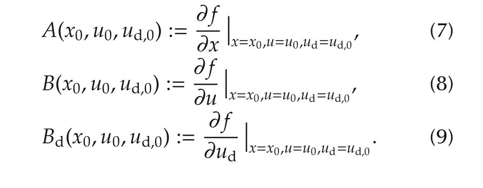
To obtain the LPV model(5)of the system,first equilibrium points and state space matrices in(7)–(9)are calculated for each operating point.Then,interpolation is used to find the LPV model between the points.FAST has an ability to determine the equilibrium points by numerically solving

when a part of parameter values in x0,u0and ud,0are specified.Here,we set the platform pitch rate ˙ ppt to be zero,and the generator speed ωgand the generator torque Tgto be their rated values ωg,ratedand Tg,rated.For each fixed wind speed ud,0=v,the unspecified parameter values,ppt and β,will be determined by solving(10)using FAST.Accordingly,system matrices in the linearized model are functions of wind speed v,and thus can be represented as A(v),B(v)and Bd(v).
To obtain the parametrization of A(v),B(v)and Bd(v)in terms of v,we take the following procedure:
1)Take samples v(k),k=1,2,3,...,from the operating wind speed range.


3)Parameterize A(v),B(v)and Bd(v),e.g.,as whereA0,B0,etc.,are matrices which have compatible sizes and are to be determined in the next step.
4)Using curve-fitting techniques,obtain the coefficient matrices in(11)such that the data in step 2)are approximately interpolated.If the curve-fitting result is not satisfactory,we increase the complexity of the parametrization in step 3),and redo curve-fitting.
4 Controller design
4.1 Feedback structure for controller design
Ageneralfeedback structure forfloating offshore wind turbines is illustrated in Fig.3,which contains both state and output feedback cases.Using this feedback structure,differentcontrollers are designed for Region III.The inner structure of each controller is explained in detail in the following sections.
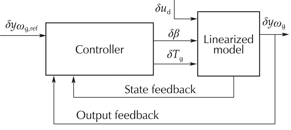
Fig.3 A general feedback structure for controller design.
In Fig.3,all the signals with δ are deviations from the equilibrium points.The feedback signals are output and state signals.As was explained in Section 3,the output signal is generator speed(yωg)and the state signals are rotorspeed(ωr),platform pitch angle(ppt)and platform pitch rate(˙
ppt).In this paper,whenever state-feedback is used,we assume thatallthe states are directly measurable by the available sensors[13,14].Also,the reference signalyωg,refis the reference for generator speed.
4.2 Baseline controller
The baseline controller for floating offshore wind turbines for Region III was introduced in[16],as depicted in Fig.4.The control inputs for NREL 5 MW are given in[16]as
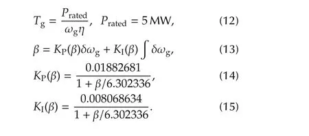
PI gain-scheduling controller takes into account dynamics variation according to operating condition change1The right hand side of(13)will determine β for the next time step..
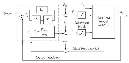
Fig.4 The baseline controller structure.
4.3 LQR controllers
The feedback structure with the LQR controller with an integrator is depicted in Fig.5,whereKxandKeare control gains for state and error signals,respectively.
An integratoris used inside the structure to reduce the steady state error for generator speed regulation,and to attenuate wind and wave disturbances.

For the LQR structure in Fig.5,both fixed(non-GS)controllers and GS controllers are designed,and hereafter,they are referred to as LQR F and LQR GS controllers,respectively.To design LQR F controllers,we use a linear time-invariant(LTI)model which is a linearized model at the middle point of the operating range(v=(11.4+25)/2=18.2 m·s−1).On the other hand,LQR GS controllers are acquired by first designing LTI controllers based on linearized models for each gridded operating point(i.e.,wind speed),and then by using the linear interpolation technique.

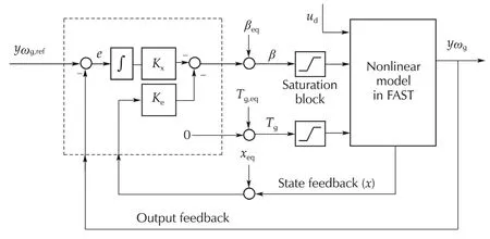
Fig.5 LQR feedback structure.
4.4 LPV gain-scheduling controllers
Two feedback structures for LPV GS controllers are illustrated in Fig.6 for designing an output feedback(OF)controller and a state-feedback(SF)controller,which are hereafter referred to as LPV GS OF and LPV GS SF,respectively.
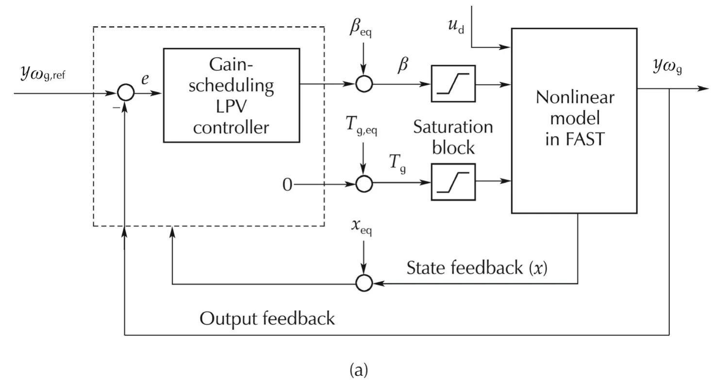
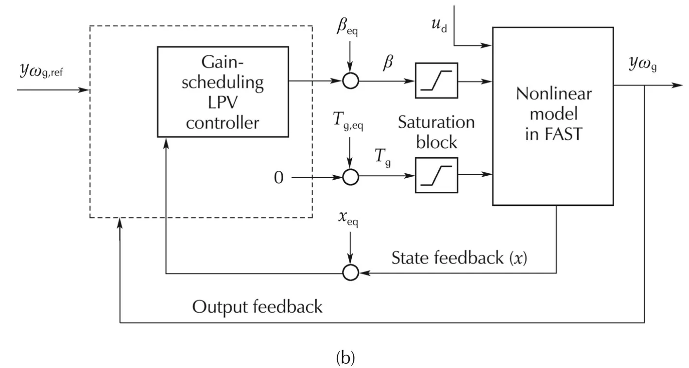
Fig.6 LPV GS feedback structures.
The LPV GS OF controller receives generator speed error and commands the blade pitch angles.To mathematically formulate a controller design problem reflecting the control objectives,we will consider the feedback structure depicted in Fig.7(a),where the control input δuis collective blade pitch angle and controllerK(v)is given as

wherexKis the controller state vector.In order to use the well-known gain-scheduling technique in[18],the closed-loop system in Fig.7(a)is reconfigured with a generalized plantG(v)as drawn in Fig.7(b).In the figure,the weighting functionsWe,WuandWpptplay roles in taking trade-off among regulation of generator speed,fulfilmentofthe controlinputconstraints,and minimization of platform pitch movement.
The procedure for designing the LPV GS SF controller is similar to that of the LPV GS OF.However,instead of feeding back generator speed,all the states are fed back.The feedback structure used for controller design and also the reconfigured structure with the generalized plant are shown in Fig.8.
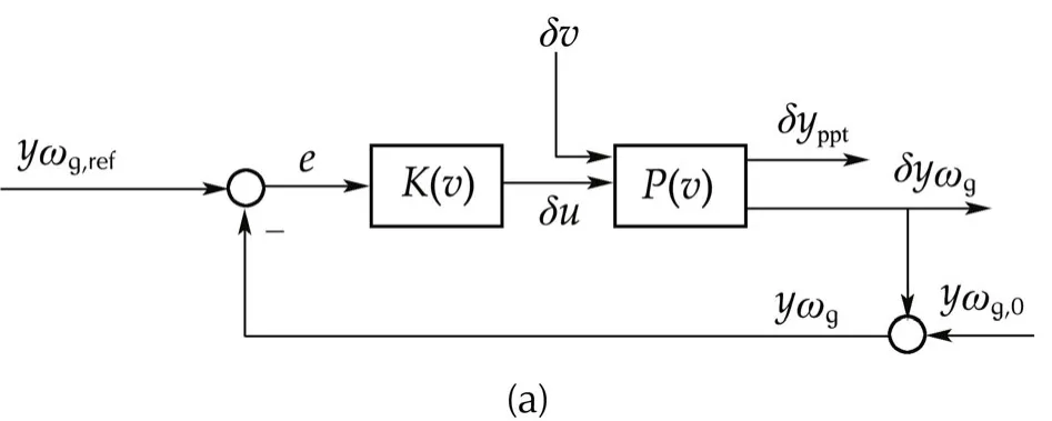
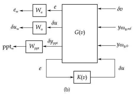
Fig.7 Feedback structures for LPV GS OF controller design.
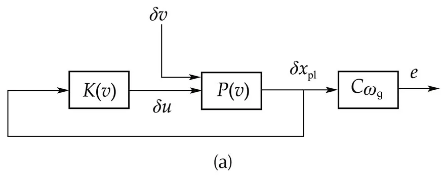
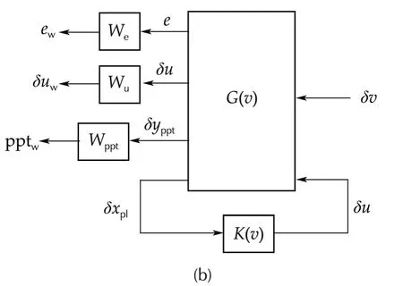
Fig.8 Feedback structures for LPV GS SF controller design.
5 Simulation results
Five controllers have been designed,that is,baseline,LQR F,LQR GS,LPV GS OF and LPV GS SF controllers.Time-domain simulations are carried out for these controllers,with simulation settings as explained in the following subsection.
5.1 Simulation settings
To evaluate the designed controllers,simulations are conducted for the closed-loop system depicted in Fig.9.Since the controllers are designed for the linearized plant,the input and output of the designed controllers are the deviation from the equilibrium points.Thisdeviation is calculated in the simulation by adding orsubtracting the equilibrium values to the related signals wherever needed.These equilibrium values for reference signal and output signal are not illustrated in this figure,because they will cancel out each other.The elements of this figure are explained next.
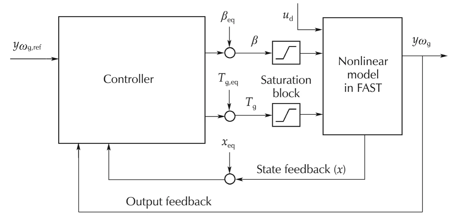
Fig.9 A general feedback structure for simulations.
The nonlinear model(2)is realized as a Simulink block.The block contains the nonlinear model with all the degrees of freedom of FAST model activated,which has 44 states and a number of inputs and outputs.
There are constraints on system inputs and their rates of changes due to the physical limitations of actuators.These constraints are realized in the saturation blocks.The constraints for the NREL 5 MW are given as β∈[0°,90°],˙β∈[−8,8](°)/s,Tg≤47402.91 N·m,and˙Tg∈[−15000,15000]N·m/s.
Wind and wave are disturbance inputsudto the system.The properties of these wind and wave profiles are shown in Table 1.The wave properties are selected for each wind speed profile using IEC Standards[19].Figs.10 show the wind profiles for these different meteorological conditions.These wind profiles are generated by software TurbSim[20].Also,wave profiles which are generated by FAST are shown in Figs.11.

Table 1 Meteorological conditions in Region III.
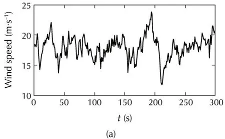
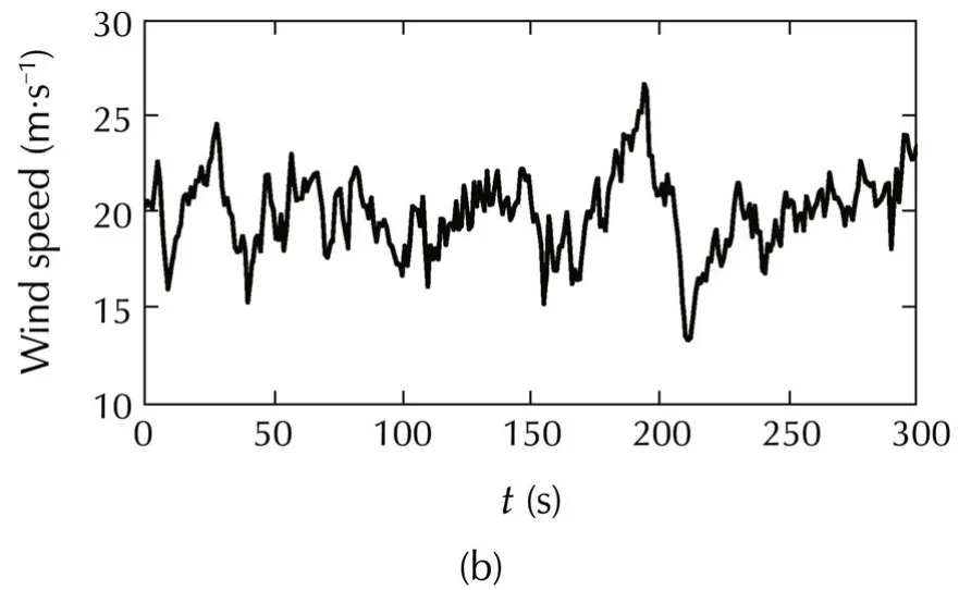
Fig.10 Wind speed profiles for simulations.
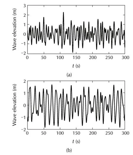
Fig.11 Wave elevation profiles for simulations.
The referenceyωg,reffor generator speed is set to the rated generated speed.The designed controllers are plugged into “Controller”block in order to compare closed-loop performances.
5.2 Performance measures for comparisons
Based on the control objectives presented in Section 2.3,several performance measures are defined in order to evaluate performance of designed controllers.The first objective is regulation of power capture.This is evaluated by taking the root-mean-square(RMS)value of the difference between the power capture and rated power.This measure is denoted byPrms.The second objective,reduction of platform motion,is evaluated by the RMS value of platform pitch angle pptrmsand its derivative ˙ pptrms.
5.3 Simulation results for the baseline controller
Simulations for NREL 5 MW with the baseline controller are conducted,with the disturbance inputs given in Figs.10 and 11.The control inputs(blade pitch angle and generator torque)and system responses(platform pitch angle and generator speed deviation)for the two meteorological conditions are shown in Figs.12 and 13.Also,the performance measures are calculated from simulation results and given in Table 2.
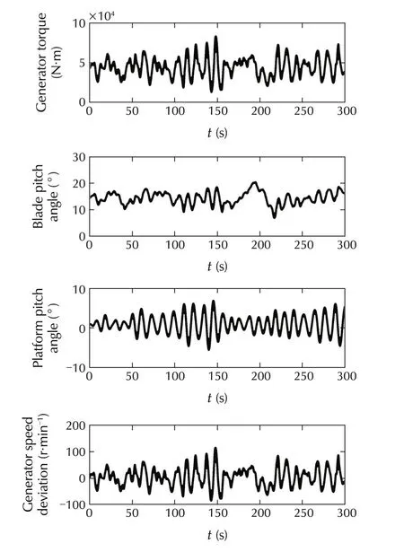
Fig.12 Control inputs and system responses for the baseline controller under Cond.I.
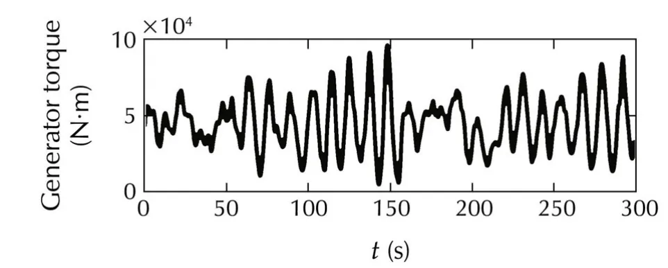
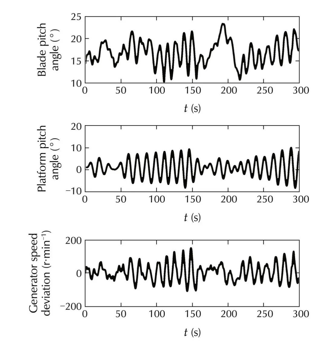
Fig.13 Control inputs and system responses for the baseline controller under Cond.II.

Table 2 Performances for the baseline controller.
5.4 Simulation results for the designed controller

For each controller,simulations are run for various design parameter values under the mentioned meteorologicalconditions.The evaluated performance measures for meteorological conditions(Cond.I and Cond.II)are shown in Fig.14.These figures show the relations between the RMS value of power regulation error and the RMS valuesofplatform pitch angle and itsrate ofchange.
By comparing the baseline controller performance in Table 2 with the evaluated performance measures for other designed controllers given in Fig.14,one can see that all the presented controller types can improve the performance measures compared to the baseline controller,by reducing both power regulation error and platform pitch movement at the same time.Specifically,power regulation has been improved substantially compared to the baseline controller.
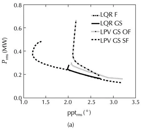
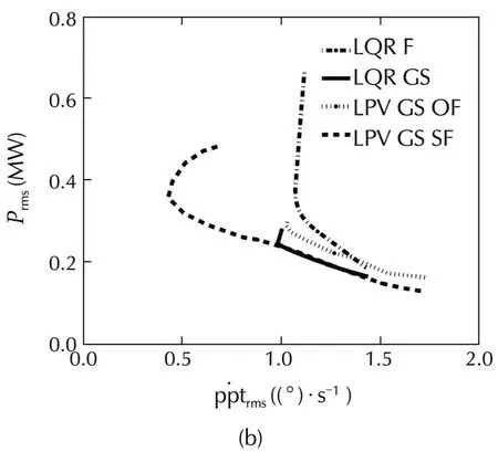
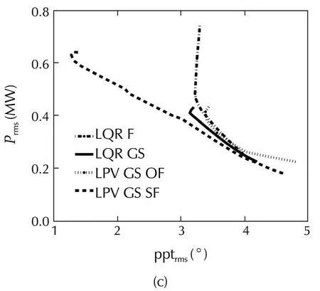
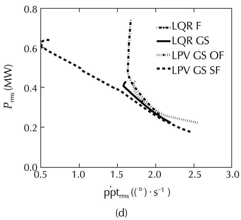
Fig.14 Error in power versus platform pitch response for different controllers.
Fig.14 demonstrates the trade-off between reduction of power regulation error and platform pitch movement for LQR controllers.However,as one can see in these figures,reduction of the platform pitch movement is restricted.By decreasingQless than approximatelyQ=10−4.0in these simulations,powerregulation willincrease withoutimprovementin the platform pitch movement.Also,improvement in power regulation is limited due to the stability issue.By increasingQmore than approximatelyQ=10−2.5in these simulations,which leads to high improvement in power regulation,the stability cannot be guaranteed using quadratic stability,even though the closed-loop system turned out to be stable in simulations.Another important result inferred from these figures is that LQR GS improves both power regulation and platform pitch compared to LQR F.The main reason for this improvement is that LQR GS is designed as a time-varying controller,with consideration of plant dynamics variations.
In Fig.14,the trade-off between the reduction of power regulation error and platform pitch movement can also be seen for LPV GS controllers.In the figures,it can be seen that the performance of the LPV GS SF controller is better than all other controllers in reducing power regulation error and platform pitch movement.
In order to compare the response of different controller structures over time,one controller from each structure is selected.The selected controller is the one which have achieved the bestreduction in platform pitch movement in that structure.The performance measures are compared in Tables 3 and 4.
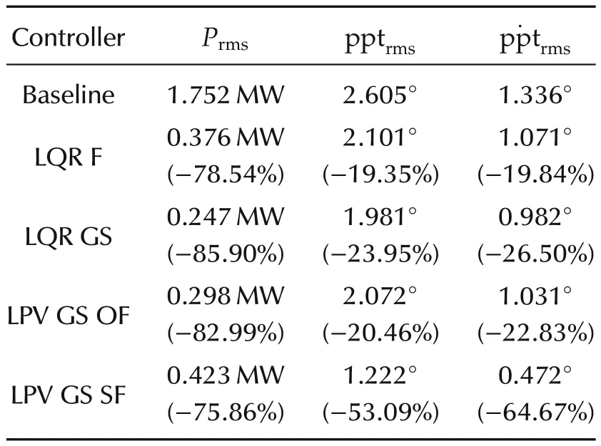
Table 3 Performances for selected controllers(Cond.I).
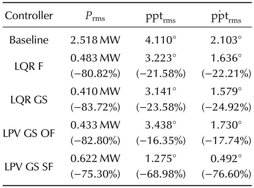
Table 4 Performances for selected controllers(Cond.II).
As one can see from Tables 3 and 4,and also time domain simulations in Fig.15,power regulation for all of the designed controllers has been improved substantially compared to the baseline controller.LPV GS SF is the best in reducing platform movements,while LQR GS isthe bestforpowerregulation.However,the LPV GS SF structure can achieve almost the same power regulation and platform pitch movement as LQR GS by changing its weighting functions.This can be seen in Fig.14(a)–(d)where the dashed curve for LQR GS SF hits the solid curve for LQR GS in all figures.
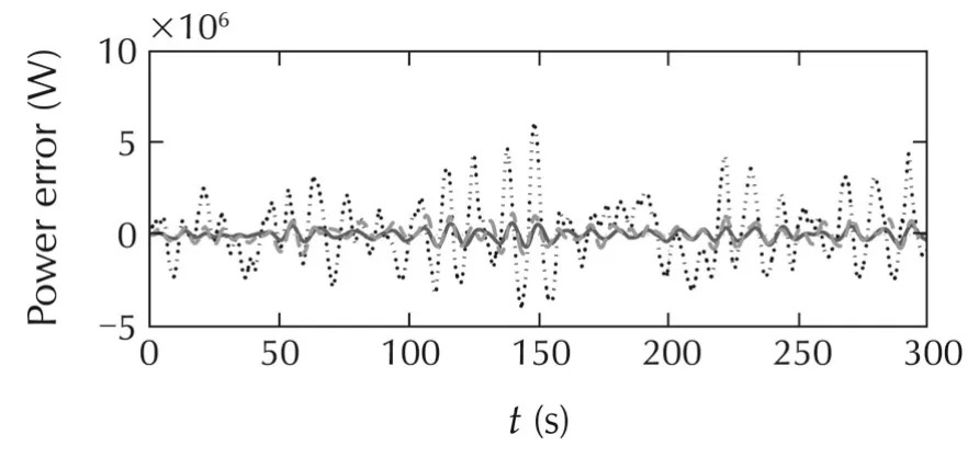
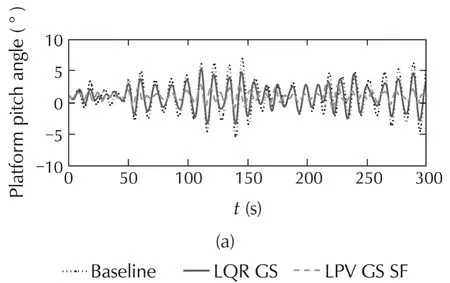
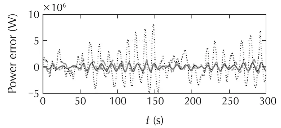
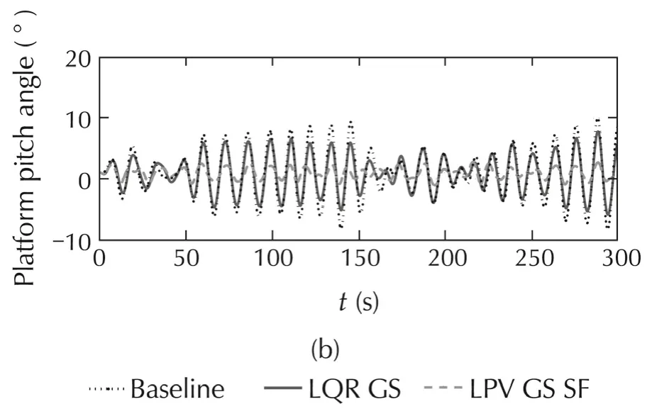
Fig.15 System responses for time-domain simulations for selected controllers.
6 Conclusions
Above rated wind speed,LQR gain-scheduling and LPV gain-scheduling controllers with both state feedback and output feedback structures were designed.These controllers were compared with the conventional controllers such as baseline and fixed LQR controllers presented in[13,16].The simulation results show that all the designed controllers have better performance compared to the conventionalcontrollerswith increased power regulation and reduced platform pitch movement.Among the three designed controllers,the LPV gain-scheduling controller with state-feedback surpassed the other two controllers,especially in platform pitch reduction.
Acknowledgements
The authors would like to thank Dr.Jason Jonkman at the National Renewable Energy Laboratory for technical advices.
[1]S.Mathew.Wind Energy:Fundamentals,Resource Analysis and Economics.Berlin:Springer,2006.
[2]W.Musial,S.Butterfield,B.Ram.Energy from offshore wind Proceedings of Offshore Technology Conference,Houston,Texas:2006:1888–1898.
[3]D.Roddier,C.Cermelli,A.Aubault,et al.WindFloat:A floating foundation for offshore wind turbines.Journal of Renewable and Sustainable Energy,2010,2(3):DOI 10.1063/1.3435339.
[4]C.P.Butterfield,W.Musial,J.M.Jonkman,et al.Engineering Challenges for Floating Offshore Wind Turbines.Golden Colorado:National Renewable Energy Laboratory,2007.
[5] J.M.Jonkman,S.Butterfield,W.Musial,et al.Definition of a 5-MW Reference Wind Turbine for Offshore System Development,Golden Colorado:National Renewable Energy Laboratory,2009.
[6]J.M.Jonkman,M.L.Buhl.FAST User’s Guide.Golden Colorado:National Renewable Energy Laboratory,2005.
[7]G.Betti,M.Farina,G.Guagliardi,et al.Development ofa controloriented model of floating wind turbines.IEEE Transactionos on Control Systems Technology,2014,22(1):69–82.
[8]P.J.Moriarty,S.B.Butterfield.Wind turbine modeling overview for control engineers.Proceedings of the American Control Conference.St.Louis:IEEE,2009:2090–2095.
[9]J.W.Van Wingerden,I.Houtzager,F.Felici,et al.Closed-loop identification of the time-varying dynamics of variable-speed wind turbines.International Journal of Robust and Nonlinear Control,2009,19(1):4–21.
[10]T.Bakka,H.R.Karimi.Robust output feedback H∞control synthesis with pole placement for offshore wind turbine system:An LMI approach.Proceedings of IEEE International Conference on Control Applications,Dubrovnik:IEEE,2012:1467–1472.
[11]M.A.Lackner,M.A.Rotea.Structural control of floating wind turbines.Mechatronics,2011,21(4):704–719.
[12]E.Lindeberg.OptimalControlofFloating Offshore Wind Turbines.Trondheim,Norway:Norwegian University of Science and Technology,2009.
[13]H.Namik,K.Stol.Individual blade pitch control of floating offshore wind turbines.Wind Energy,2010,13(1):74–85.
[14]H.Namik,K.Stol.Performance analysis of individual blade pitch control of offshore wind turbines on two floating platforms.Mechatronics,2011,21(4):691–703.
[15]T.Bakka,H.R.Karimi,N.A.Duffie.Gain scheduling for output H∞control of offshore wind turbine.Proceedings of the 22nd International Offshore and Polar Engineering Conference.Rhodes,Greece,2012:496–501.
[16]J.M.Jonkman.Dynamics Modeling and Loads Analysis of An Offshore Floating Wind Turbine.Golden Colorado:National Renewable Energy Laboratory,2007.
[17]J.R.Homer,R.Nagamune.Control-oriented physics-based models for floating offshore wind turbines.Proceedings of the American Control Conference.Chicago,Illinois:IEEE,2015.
[18]P.Apkarian,R.J.Adams.Advanced gain-scheduling techniques for uncertain systems.IEEE Transactions on Control Systems Technology,1998,6(1):21–32.
[19]T.Burton,N.Jenkins,D.Sharpe,et al.Wind Energy Handbook.New York:John Wileyamp;Sons,2011.
[20]B.J.Jonkman.TurbSim User’s Guide:Version 1.50.Golden Colorado:National Renewable Energy Laboratory,2009.
the B.Sc.degree in Mechanical Engineering from the Sharif University of Technology,Tehran,Iran,in 2011,and the M.Sc.degree in Mechanical Engineering from the University of British Columbia,Vancouver,Canada,in 2013.Since 2013,he has been with the Department of Mechanical Engineering,University of California,Berkeley,as a Ph.D.candidate.His current research interests include control applications to servo systems and wind turbines.E-mail:omidba2@gmail.com.


Ryozo NAGAMUNEreceived the B.Sc.and M.Sc.degrees from the Department of Control Engineering,Osaka University,Japan,in 1995 and 1997,respectively,and the Ph.D.degree from the Division of Optimization and Systems Theory,RoyalInstitute ofTechnology,Stockholm,Sweden,in 2002.From 2003 to 2006,he was a postdoctoral researcher at the Mittag-Leffler Institute,University of California at Berkeley,Berkeley,CA,U.S.A.,and the Royal Institute of Technology.He has been with the Department of Mechanical Engineering,The University of British Columbia,Vancouver,BC,Canada,since August 2006,where he is currently an associate professor.From September to December 2013,he was a visiting researcher at the National Wind Technology Center of the National Renewable Energy Laboratory,Golden,CO,U.S.A.His research interests include robust control theory and applications to mechatronics systems,such as hard disk drives,machine tool drives,automotive engines,and wind turbines.Dr.Nagamune received the IEEE CDC Best Student Paper Award in 2001,and the Best Paper Award at the 23rd Canadian Congress of Applied Mechanics in 2011.He is an associate editor of the ASME Journal of Dynamic Systems,Measurement and Control.He is a chair of the IEEE Joint Chapter of Control Systems,Robotics and Automation,and Systems,Man,and Cybernetics Societies in the Vancouver Section.He received the Canada Research Chair,Tier 2,in Control Engineering.E-mail:nagamune@mech.ubc.ca.
†Corresponding author.
E-mail:nagamune@mech.ubc.ca.Tel.:+1-604-827-4344;fax:+1-604-822-2403.
This work was supported by the Natural Sciences and Engineering Research Council of Canada(NSERC)(No.11R82911)and the Institute of Computing,Information and Cognitive Systems(ICICS)at the University of British Columbia.
©2015 South China University of Technology,Academy of Mathematics and Systems Science,CAS,and Springer-Verlag Berlin Heidelberg
杂志排行
Control Theory and Technology的其它文章
- Distributed dynamic pricing based on demand-supply balance and voltage phase difference in power grid
- Decentralized load frequency control for two-area interconnected power system
- Increasing the operating area of shunt active filters by advanced nonlinear control
- Simple adaptive air-fuel ratio control of a port injection SI engine with a cylinder pressure sensor
- Estimation and feedback control of air-fuel ratio for gasoline engines
- New adaptive vector control methods for induction motors with simpler structure and better performance
