Increasing the operating area of shunt active filters by advanced nonlinear control
2015-12-05AndreaTILLIChristianCONFICONI
Andrea TILLI,Christian CONFICONI
Center of Complex Automated Systems(CASY)at Department of Electrical,Electronic and Information Engineering(DEI),University of Bologna,Viale Risorgimento 2,40136 Bologna,Italy
Received 5 September 2014;Revised 10 April 2015;Accepted 10 April 2015
Increasing the operating area of shunt active filters by advanced nonlinear control
Andrea TILLI,Christian CONFICONI†
Center of Complex Automated Systems(CASY)at Department of Electrical,Electronic and Information Engineering(DEI),University of Bologna,Viale Risorgimento 2,40136 Bologna,Italy
Received 5 September 2014;Revised 10 April 2015;Accepted 10 April 2015
This work is aimed to rigorously manage voltage saturation and maximum current constraints in Shunt Active Filters.In this respect,assuming “unconstrained”control algorithms have already been defined to achieve standard objectives for such devices(i.e.current tracking for harmonic compensation and DC-bus voltage boundness),a plug-in unit,oriented to extend the system operating region and at the same time preserving good performance under large transients and overload conditions,is presented.This solution allows to improve availability,robustness and composability of Shunt Active Filters,which are expected to be key features in present and next generation complex and possibly “smart”power grids.The proposed unit is composed by two parts.First,a suitable anti-windup strategy is defined in order to deal with control input saturation.Its main purpose is to preserve the original“unconstrained error dynamics”,in face of input saturation,while guaranteeing low computational burden and reduced performance impairment(the latter goal,in harmonic compensation context,leads to rather non-standard problem formulation).To this aim,the anti-windup acts on the current references through a suitably-designed additional dynamics.Then,in order to cope with current limitations,an additional strategy has been designed;again the current references is suitably shaped to comply with the features and bounds of the system,augmented with the above-mentioned anti-windup solution.The proposed scheme can be simply joined to any kind of unconstrained controller adopted to steer Shunt Active Filters.In this work,an Internal-Model-based current controller is adopted as a benchmark case.The proposed approach is validate through extensive simulation tests.
Shunt active filters,power quality,anti-windup units,control of constrained systems
DOI 10.1007/s11768-015-4122-6
1 Introduction
Nonlinear loads,such as motor drives,power electronics rectifiers,absorbing undesired current harmonics,are the main cause of AC mains pollution.Harmonic currents determine additional power losses,worsen the system power factor and can impair correct operation of the equipment connected to the perturbed line grid,which is expected to work with sinusoidal voltages and currents.
The so-called active power filters(APFs)[1]are nowa-days the most widely used devices exploited to cope with this issue.A specific kind of APFs,are the shunt active filters(SAFs)[2],whose purpose is to inject proper currents into the mains,in order to compensate,partially or totally,the effects of the distorted load current.The SAF topology considered in this paper consists of a three-phase three-wire AC/DC boost converter[3],connected in parallel to the distorting load(see Fig.1).A DC-bus,or DC-link,capacitor provides energy storage functionality,while the inductances are exploited to steer the filter currents by means of the converter voltages.The switching devices of the three-legs bridge(also called “inverter”)are usually realized by IGBTs and free-wheeling diodes.
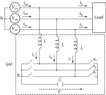
Fig.1 Shunt active filter topology.
From a control theory viewpoint,several approaches have been presented in the literature(see[2]for an overview),the main distinguishing marks are the algorithms adopted to steer the SAF current injected into mains and the solutionsused to controlthe DC-link voltage.As regards the current control,high performance hysteresis[4],and current predictive solutions[5,6],have been proposed.More recently,nonlinear[7]and adaptive[8]current controllers,based on input-output linearization methods,have been presented,while in[9,10,11],the internal model principle(IMP)has been exploited to design a robust current control solution.
A different control approach is to consider the mains current vector,in place of the filter currents,as the controlled output,achieving indirect harmonic compensation.The iterative learning controller proposed in[12],and the hysteresis control,based on adaptive estimation of the load fundamental component,elaborated in[13],belong to this category.
As far as DC-link voltage control is concerned,it must be remarked that the uncontrolled voltage dynamics is an oscillating and unstable zero dynamics w.r.t.current tracking objective[11].Oscillations structurally stem from the power exchange linked to harmonic compensation.On the other hand,instability,caused by unavoidable power losses,has to be handled.To this aim,additional current is usually drawn from the line grid.Under steady-state scenarios and suitable DC-link capacitor sizing,it can be shown that there exists a constant active current value,stabilizing the DC-link voltage and saving the needed oscillations[10].This is particularly attractive,since perfect asymptotic harmonic compensation can be preserved while stabilizing the internal DC-bus voltage dynamics.The additional current term is commonly provided by a dedicated control unit,exploiting the DC-link voltage measurements to modify the reference of the adopted current controller.In[14],an averaging control strategy is proposed to deal with DC-link stabilization,neglecting oscillations.In[15],the DC-link voltage dynamics is linearized and a low-pass linearvoltage controlleris adopted;while,in[16],a nonlinear PI controller is exploited to improve the voltage response.
Almost all the advanced control strategies proposed and implemented in state-of-the-art SAFs have been developed without considering explicitly the physical limits of such devices,namely the actuation saturation,the maximum admissible voltage on the DC-link capacitor and the maximum current of the converter switches.If a suitable device sizing procedure is carried out[11,17],a range of nominal operating conditions,under which the system limits are not hit,can be defined and adopted to design controllers,neglecting constraints.Anyway,in actual industrial applications,SAFs often face“offnominal”conditions,mainly related to line voltage and load current variations,which could lead the system to operate outside its nominal working area.In such situations,state-of-the-art SAFs typically just turn off,or keep working with heavily downgraded compensation capabilities.Such responses to non nominal scenarios impair SAFs performance,availability and even composability with other grid elements.This issue is crucial,expecially if SAFs have to operate in complex,and possibly “smart”,grid topologies,where demanding robustness,performance and reliability indexes are typically required.Therefore,suitable control countermeasures seem very importantto withstand off-nominaltransients and to extend the SAF operating range,avoiding component oversizing and ensuring,at the same time,graceful performance derating.
The aforementioned system limits can be mapped into norm saturation,for what concerns the control input vector(given by the inverter legs duty cycles),while a bound on the norm of filter currents vector needs to be guaranteed,along with an upper bound on the DC-link capacitor voltage(clearly,it has to be kept positive,as well).
The last constraint is usually the less stringent;very large capacitor values are commonly adopted in SAFs[17],and therefore,a DC-link controller satisfying the voltage constraints under nominal conditions is usually able to guarantee proper voltage behavior even under off-nominal situations,provided that current constraint and control input saturation are suitably handled.Therefore,the crucial limits to deal with are related to control input and current.
Control input saturation is typically managed by joining a suitable anti-windup compensator to the unconstrained original controller,with the aim to preserve as much as possible the unconstrained system performance.In the last decade,several techniques,regarded as“modern”anti-windup approaches,have been made available to deal rigorously with stability and performance preservation.In this context,three main categoriescan be outlined:command orreference,governor(CG),model recovery anti-windup(MRAW),and direct linear anti-windup(DLAW).CG approach consists of modifying the system reference,finding the bestapproximation of the original one which allows to comply with the system inputand state constraints.Receding horizon Model Predictive Control(MPC)framework is typically exploited to implement this concept(see[18,19]and references therein).
In contrast,MRAW and DLAW solutions act directly on the control input.In MRAW schemes,first proposed in[20,21],the anti-windup system basically replicates the plant model and is driven by the mismatch between the unconstrained control input and the saturated value;in addition,the control action is suitably modified in order to steer the constrained system response as close as possible to that of the unconstrained system,providing stability properties.DLAW schemes are based on a linear anti-windup compensator,which has to be designed in order to achieve stability and performance level optimization.Both the approaches can be arranged as LMI-based optimization problems(see[22,23]for a comprehensive overview of MRAW and DLAW methods).In this paper,a novel plug-in unit is proposed for being added to SAFs,equipped with their nominal controllers.The main goal of such unit is to handle explicitly the control input saturation and the current limits to achieve the following objectives.
a)To enlarge the SAF working area,beyond the nominal one,in terms of sustainable line voltage and manageable current harmonics.
b)To guarantee maximum performance in nominal conditions and to provide a slight reduction in all manageable off-nominal situations.In particular,no additional harmonics have to be injected in the line in any steady-state condition(this is of utmost importance since the main objective of SAFs is to compensate for distortion,and thus,new spurious currents are unacceptable).
c)To preserve the original current tracking error dynamics.In this way,the overall stability and tracking properties stem directly from the characteristics of the unconstrained controlled SAF and the features of the proposed plug-in unit,considered independently.Indeed,this makes the proposed unit an easy-to-plug-in unit.
d)To save a proper margin,allowing the nominal DC-link controller to handle the voltage dynamics properly,even in off-nominal conditions.As already mentioned,the DC-link voltage bound is usually less stringent w.r.t.current and control bounds,thanks to large capacitor sizing.Nevertheless,some attention has to be paid in defining the strategy for handling the latter bounds in order to achieve a sort of“intrinsic”verification of the voltage constraint,even in off-nominal conditions.
The objectives above are ensured by the proposed plug-in system,modifying the current reference and adding a suitable feed-forward action on the control inputs.CG or MPC methodologies could look suitable alternatives,since they would allow to cope with all the system limits by a single step design procedure.Nevertheless,the previously outlined objectives are rather non standard for those frameworks.Current error dynamics preservation is not a common specification,as well as the composabilty of the stability properties of the independent units.In addition,the crucial request on no injection of additional harmonic pollution,coming from constraints management,is hard to be formulated in CG or MPC context.Moreover,plant nonlinearity would demand a significant computational effort to solve on-line the constrained optimization problems arising in CG and MPC approaches.For these reasons,a multiple stages approach has been considered in designing the proposed unit.First,a suitable relaxation of the problem has been considered,then,at each step,additional objectives and constraints have been added.Although in general a suboptimal solution is obtained,this allows to outline a simple and effective procedure to tackle the problem.The resulting solution is composed by two elements,an anti-windup unit,dealing mainly with control saturation,and an harmonic reference manager,dealing with the constraints on the leg currents and tacking care of the characteristics of the adopted anti-windup unit.Both of these units will preserve some margin for DC-link voltage control.The proposed multi stages design reads as follows:
1)Focusing on the solely control input constraints,disregarding current bound(as well as the DC-bus dynamics preservation under saturation),the anti-windup system is designed in order to achieve the aforementioned objective c)and,to some extent,objectives a)and b).A suitable “additional dynamics”is defined,to generate the reference correction,along with a feedforward action to be added to the original control action.
2)The anti-windup strategy is slightly modified to take into account requirements stemming from DC-bus voltage dynamics preservation under saturation(objective d)).Only reactive current is used for anti-windup purposes.
3)The anti-windup units dynamics are steered towards a piecewise constant steady-state current modification.Hence,spurious harmonics related to the antiwindup unit are prevented(objective b)).The main insight to achieve this behavior is to exploit the periodicity of the harmonics to be compensated for.In this way the resulting additional current to deal with control action saturation is,in steady-state,a constant reactive current.Thislooks profitable,since thiskind ofadditionalcurrent in the line grid can be easily compensated by standard capacitor banks.
4)The effects of the previous changes in the antiwindup unit,in terms of shrinking the achievable working region(objective a)),are carefully analyzed.Then,the current limit is introduced and the strategy for the harmonic reference manager is defined.Suitable margins are saved for DC-link voltage control(objective d))and to take into account current tracking and antiwindup dynamics.
The paperisorganized asfollows.In Section 2,the SAF mathematical model is derived and the control objectives are formally recalled.Control and state bound are presented,and a sizing approach to neglect them under nominal conditions is mentioned.Then,the IMP-based current controller,presented in[9,10],is briefly recalled,since itwillserve as an unconstrained benchmark solution for the application of the proposed plug-in unit.In Section 3,the SAF control input and current limitation problems are elaborated,their causes are discussed and the consequences produced by critical events,such as line voltage amplitude variations and too large load current harmonics,are shown via simulation tests.In Section 4,the anti-windup unit is presented;first,the main ideas underlying the current control anti-windup approach,are introduced for a generic class of systems;then,the specific solution,regarding the SAF is introduced,and the improvements defined in items 2)and 3)are discussed.A very preliminary and incomplete version ofsuch parthas been presented in[24].In Section 5 the harmonic reference manager is defined,according to item 4)of the previous list.The control input feasibility set is analyzed,accounting for the current constraints and assuming the system has been augmented with the proposed anti-windup unit.Then,a numerically tractable optimization problem is formulated,in order to approximate the maximum feasible reference current,and define a proper current reference limitation strategy.Simulation testsare presented along the abovementioned Sections to underscore the specific features of the adopted solutions.Section 6 ends the paper with some discussion on the proposed method and future work directions.Appendices contain some technical details of the above-mentioned sections.
2 SAF system
Notation reported in Fig.1 will be adopted to denote the system variables;vm=[vmavmbvmc]Tis the mains voltage vector,im=[imaimbimc]Tare the mains currents,il=[ilailbilc]Tis the nonlinear load current vector,i=[iaibic]Tare the filter currents,while C,v are the capacitor value and the corresponding voltage and L is the inductances value.
The inverter switches commands are denoted as u1=[uxuyuz]T;due to the converter switching nature,such vector is enforced to range on a discrete set consisting of eight possible configurations(each component can be either 0 or 1).However,if a PWM(pulse width modulation)strategy is used to control the in-verter,by averaging theory,each leg control input can be considered such that ui∈[0,1],i=x,y,z(see[3]for details).
2.1 Model and control objectives
According to the standard two-phase representation of three-phase systems,and exploiting the so-called dq synchronous rotating reference frame,aligned to the mains voltage vector,the SAF model can be written as follows(see[25],[26],and references therein fordetails)

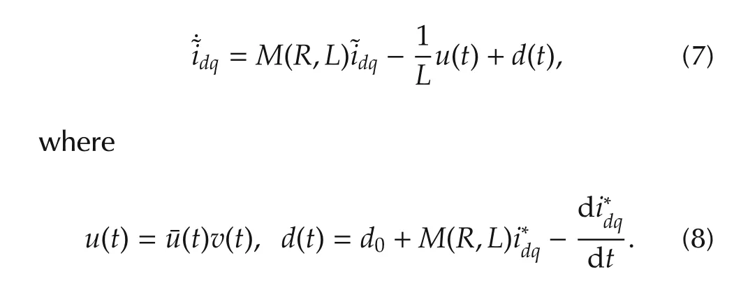
where Vmis the mains voltage amplitude,and R is the inductances parasitic resistance value;while ωmis the line angular frequency and¯u=[¯ud¯uq]T,idq=[idiq]are,respectively,the filter command input and current vectors,expressed in the rotating reference frame.Assuming that PWM techniques are exploited to actuate the desired control vector,it can be showed that¯u has to lie in a connected compact set in R2[11,17],which will be specified later on.
As regards the nonlinear load current vector il,its components can be approximated by the sum of a finite number of harmonics[27].Adopting the same synchronous coordinate setting,used in(1),yields

According to[27],the synchronous reference frame allows to split each current vector(i.e.,SAF current,load current,main current)in real,or active,part(the d-component),and virtual,or reactive,part(the qcomponent).Equivalently,active-reactive power variables,in place ofthe currents,can be adopted to express model(1)and load harmonics in(2)(see[11]).This reference frame choice allows a natural formulation of the control problem,and simplifies the regulator design.
Roughly speaking,the main control objective for SAFs is to steer their currents in order to cancel out the undesired load harmonics at the line side.This would qualify the issue as a standard output tracking problem.However,the DC-link voltage differentialequation represents an internal dynamics that needs to be carefully managed,since the DC-link provides the control authority to steer the filter current(see the first equation in(1)),then its voltage is usually required to belong to a given positive interval.We refer to[10],[11]for a comprehensive discussion of such part,next,the main points are summarized to recall the control problem properly.
If the purpose is to perfectly compensate for the load current harmonics,it can be verified that the corresponding DC-link voltage zero-dynamics results oscillating and drifting toward zero.The latter means that no positive interval can be adopted as positive invariant set,leading to a sort of instability of the DC-link voltage dynamics.In brief,while oscillations are unavoidable for harmonic compensation,instability is due to power losses on the parasitic resistance R.A natural choice to cope with this non-minimum phase behavior is to modify the filter current reference,in order to drain power from the grid and balance the powerlosses,making positive invariantthe desired positive intervalfor v(t).By the way,such reference modification should not impair the harmonics cancellation performance and the related v(t)oscillations.In this respect,it seems reasonable to seek for a modification of the filter current restricted to the d-component,which,in addition,under stationary load profiles,should tend to a constant value(corresponding to sinusoidal signals aligned with the mains voltages,in the standard three-phase reference frame).By physical considerations,it can be shown that such constant value,here denoted as ϕ0,can be determined by solving the following power balancing equation[10,11]

Bearing in mind these considerations,the SAF control problem can be formally posed as follows[10]:
O1)The instantaneous filter currents have to asymptotically compensate for the oscillating component of the load current real component,and for the load current reactive component.In addition,an active current component η has to be provided according to the following objective O2).Then,the ensuing reference has to be tracked:


O2)Given a safe voltage range[vmvM],assuming v(t0)∈[vmvM],by acting on the above mentioned η,the following condition must be fulfilled v(t)∈[vmvM],∀t> t0.In addition,under steady-state harmonic scenario,η is required to recover asymptotically the power loss term ϕ0defined in(3).
The two control objectives are interlaced and possibly in contrast each other.However,with a suitable SAF sizing,contrast can be avoided and feasibility can be a-priori guaranteed,as recalled in the next section.
Two separate controllers are usually adopted to tackle the problem;a current tracking controller and a DC-link voltage stabilizer,designed to handle O1)and O2),respectively.As mentioned in the Introduction,this control topology is commonly designed disregarding the system control input and current constraints,assuming a predefined set of nominal operating conditions.
Next,the system constraints are formulated in terms of norm bounds on the model control input and state variables.Nominal conditions allowing to neglect them in control design are enlighten.Then,a possible unconstrained control unit,that will serve as a benchmark for the proposed saturated control solution,is presented.
2.2 Control and current bounds
The SAF system is subject to three main limitations:a finite control authority due to the limited voltage on the converter legs,that clearly can not exceed the DC-bus capacitor voltage,a maximum current that the converter switches can provide,and a limitation on the DC-bus voltage oscillation amplitude during compensation,which can notraise beyond the setdefined in O2).While the latter constraint is explicitly considered in standard controlproblem formulation,inputand currentlimitsare not.Here,we elaborate on these constraints,in order to derive inequalities involving the input and current state variables of the SAF model(1).Then,we recall briefly as such limits can be handled at sizing stage and neglected in control design,but only under nominal conditions.
As regards the limitation on the inverter voltage,recalling the averaging effects ofPWMtechniques(applied to the converter switches in order to obtain the desired legs voltages)and by(8),it can be mapped on a norm constraint for the control vector¯u.After some computations,it turns out that¯u has to belong to the hexagon reported in Fig.2(see[11,17]for details).
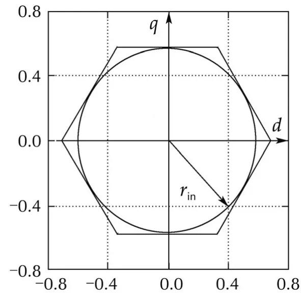
Fig.2 Control input feasibility space.


For what concerns the system current constraint,recalling(4),it can be expressed as the following inequality:


Fulfillment of inequalities(5)and(6),as well as the feasibility ofO1)and O2),clearly depends on the system parameters,the nonlinear load profile,and,in principle,the adopted control law.As shown in[11,17],a suit-able sizing procedure can be defined to deal with the above issues for a set of nominal working conditions.This nominal set is defined by a set of possible nonlinear load current profiles and an interval of admissible line voltage values.Moreover,saving a suitable margin in such sizing procedure,current and voltage controllerscan be designed neglecting the above-mentioned bound,because it can be reasonably assumed that the input-state trajectories of the controlled system never hit the bounds,providing that the working conditions of SAF are always inside the nominal set and the initial values of the state variables are suitably bounded.This is the implicit assumption,usually underlying the design of state-of-the-art SAF controllers.
2.3 Unconstrained control solution
Here,we briefly recall a possible control solution,designed to achieve the objectives stated in Section 2.1.We adopt the algorithms presented in[10,11],please refer to such references for complete presentation and formal analysis.According to common approaches,it is assumed that a sizing procedure,as the one recalled in Section 2.2,has been already applied and,then,the issues related to O1)and O2)feasibility and state-input bounds can be disregarded,under a suitable set of nominal working conditions.In this respect,we can refer the recalled control solution as unconstrained.

Here,relying on a suitable voltage stabilization algorithm which will be discussed later,v(t)is assumed measurable and always in[vm,vM].

with Γi∈ R1×2N+1suitably defined known vectors,and the matrix Ω ∈ R(2N+1)×(2N+1)defined as blkdiag(Ωj),with Ω0=0 and

Then,the following internal model based controller can be defined:
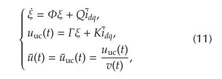
where Φ = blkdiag(Ω,Ω) ∈ R(4N+2)×(4N+2),Γ =blkdiag(Γd,Γq)∈ R2×(4N+2),while Q and K are matrices to be chosen in order to stabilize the following closedloop error dynamics,resulting from the interconnection of systems(11)and(7)(see[10,11]for further details)

where˜ξ=ξ−Lw(t).Note that the unconstrained control action¯uuc,imposed at the SAF input¯u,is always well-defined according to the assumption on the DC-link dynamics v(t).
Tuning the internal model controller on the exosystem(9),allows to extract(from the load current measurements)and compensate for a defined set of N load harmonics,modeled by the bank of oscillators in Ω,while the integrators provide robustness w.r.t.parametric uncertainties,and allow to estimate and compensate for the load reactive fundamental component Ilq0.
Regarding the DC-link voltage stabilization,the solution reported in[11](based on[10,14,28])is considered here.Details are not reported for brevity,such controller is able to meet,under nominal conditions,the requirement O2),acting on the reference modification η and guaranteeing overall system stability,when combined with the above-mentioned current controller.
3 Issues from off-nominal working conditions
In the previous section,we sketched a controlscheme able to comply with the system objectives without violating the SAF physical constraints,assuming system components have been properly sized,and provided that some nominal working conditions are verified.
Nevertheless,in industrial environments,several unpredicted situations may occur,that can bring the system not to operate in the predefined scenarios.As a result,bounds could be hit and violated,even if a correct system sizing and controller design were carried out.For SAFs,three main kind of off-nominal conditions can take place:mains voltage amplitude fluctuations outside the predefined range,excessive harmonic compensation request,initial conditions beyond the assumed possible set.Each of these can induce violation of the constraints defined in Section 2.2.

As regards constraint(6),obviously high currentreferences and initial tracking error,produced by large nonlinear loads,cannot be totally compensated if the maximum filter current is exceeded.Moreover,unsuitable handling of control input saturation could give violation of current limits,as well.
Depending on the particular scenario and system parameters,only input saturation can take place(e.g.,in case of limited line voltage steps),only current saturation can occur(e.g.,if vmis set to high values but Imaxis relatively small),or both constraints can be hit(e.g.,in case of highly unfeasible harmonics compensation request).
Actually,even the constraints on the DC-link voltage oscillations,expressed by objective O2)in Section 2.1,can be violated,for instance in case of load harmonics larger than what assumed at sizing stage,in particular to select vmand C[11,17].However,SAF capacitors are usually oversized to limit voltage oscillations and increase their expected life[17].Thus,the potential violation of O2),in actual applications,cannot take place“by itself”,but it can occur only as a consequence of incorrect handling of control input saturation and current limits.Therefore,the focus will be on these two phenomena,induced by off-nominal working conditions,and their possible effects.When not managed properly,they generate very pernicious effects,as“bad”filter currents,very far from the expected ones,and dangerous values,possibly leading to SAF sudden disconnection for protection,hence impairing the availability of such systems.In orderto confirm this statement,Fig.3 shows the consequences of control input saturation induced by a 20%increase of mains voltage amplitude.Simulations have been carried out considering a SAF equipped with the unconstrained control of Section 2.3.Its parameters are reported in Table 1,while the nonlinear load current profile consists of two harmonics with 5 A amplitude at frequency 7ωmand 13ωm,respectively.When the line voltage amplitude increases(at time t=1.5 s),a strong degradation of compensation performance occurs and highly distorted currents are injected on the line grid,as the main current waveform in Fig.3 shows.Moreover,when the mains voltages amplitude is restored to its nominal value(at time t=3 s),the windup effect is clearly present on the control inputs,this causes strong oscillations of the mains currents.
For SAF applications,particular attention has to be paid to reduce as much as possible the occurrence of these critical behaviors,since each of them is reflected to the line grid.
Therefore,suitable anti-windup and current limitation solutions need to be joined to the unconstrained controller to deal with off-nominal conditions.
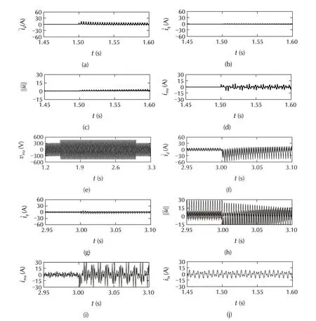
Fig.3 System performance under line voltage 20%increase in the interval[1.5,3]s:transition from nominal to saturation condition(a)–(d)and viceversa(f)–(i),with large windup effect;main voltage trace(e),showing the temporary increase,and load current trace(j),with variation along the test.

Table 1 Parameters of the considered system.
4 Anti-windup approach in current control
In this section,the proposed anti-windup unit to handle input saturation is presented,without considering current limits.The basic idea is sketched referring to a generic class of systems,then the technique is specialized for SAF application;finally,additional improvements are discussed in order to cope with DC-link voltage preservation and achieve better harmonic compensation under saturation conditions.
4.1 General idea
Assume that,for a given system,a suitable controller has been already designed in order to ensure the desired stability and tracking properties,disregarding the inputs constraints.The purpose here is to design an antiwindup unit such that the closed loop error dynamics of the unconstrained system is preserved in any working condition,even if leading to input saturation(see objectives a)and b)in the Introduction).Thus,all the results coming from the unconstrained design can be saved and reused when saturation is taken into account.Moreover,the stability and performance properties of the overall scheme have to stem directly from the original error dynamics and the anti-windup unit,without any combined analysis and/or redesign(see objective c)in the Introduction).
A possible “natural”way to approach this problem is to modify the reference to be tracked by the system,adding a suitable feedforward action,related to the reference modification.In this way,it looks reasonable and feasible to impose no modification on the tracking error dynamics,while the control input windup is avoided.In particular,the proposed approach is expected to be effective when the original reference is unfeasible,but also when unexpected significant disturbances acts on the system,or initial condition of the error dynamics are very far from the origin.
This philosophy shows similaritieswith the CGframework,however here the main objective is to preserve the closed-loop system original tracking dynamics.The feedback effects of the reference correction have to be totally masked on the tracking error dynamics,even at the cost of some optimality.Moreover,next,the design is carried out in the continuous-time domain by injecting into the system a suitable “additional dynamics”that generates the reference correction without requiring the on-line solution to an optimization problem.
The main concepts will be presented considering the following simple but explicative system:


has been designed to meet the required specifications for the ensuing closed loop tracking error dynamics

Now,assume that the control input u has to belong to a connected compact set U⊂Rn.As claimed before,the basic idea of the proposed approach is to introduce a reference modification xawand to add a suitable control action g(xaw,·),such that
.u(t)=c(·)+g(xaw,·)∈ U,∀t;
.for each condition s.t.c(·) ∈ U,xawis null or it tends to zero in some way;and


Atthis point,in orderto fulfillallofthe above-mentioned objectives,xawneeds to be designed in order to be bounded and to guarantee what follows


which is required to guarantee bounded xawand objectives A)and B).
As regards the first objective A),following a sort of“parsimony principle”,a reasonable choice seems to design the dynamics in order to minimize g(xaw,·);and this term should be null whenever c(·) ∈ U,while it should keep the overall control action on suitable points of∂U(i.e.,the feasible set boundary),whenever c(·)∉ U.However,it is easy to guess that,with such approach,no degree-of-freedom could be preserved to satisfy objective B)and to guarantee a bounded and“reasonable”behavior of xaw(i.e.,dynamics(18)could resultpoorly damped oreven unstable).In orderto cope with this issue,a sort of constrained minimum-effort control problem could be formulated.Alternatively,a simpler,even if “suboptimal”,approach is to save a(possibly small)part of the control action to shape the xawdynamics.We proceed as follows;given raw>0,define Ur={u ∈ U s.t.dist(∂U,u)≥ raw}1Here and next dist(S,x)denotes the distance of x from the set S defined as.Note that Urlies in the interior of U and between ∂Urand ∂U there is a “stripe”of width raw.Obviously,rawcannot be too large,otherwise Ur=Ø;but,as it will be clear next, “small”rawwill be considered in the proposed procedure.

Then,h1can be designed in order to minimize ‖g1‖,giving c(·)+g1(·) ∈ Ur,neglecting any issue related to xawbehavior;while h2can be exploited to shape xawdynamics.In order to meet the constraint u(t)∈U,h2has to be saturated as‖h2‖≤ raw.Obviously,rawshould be selected as low as possible in order to make Urvery close to the original U and not to “waste”too much control authority with this a-priori preservation.

4.2 Application to the SAF case
The system given by the interconnection of the SAF current subsystem,obtained by(1)neglecting the DC-bus voltage state equation,and the internalmodel-based controller(11),matches the general form reported in(13)and(14).Moreover,the resulting closed-loop current error dynamics can be shown to be similar to what in(15),with the matrix M(R,L)playing the role of the vector field f,while,according to(5),the admissible control set for the input vector is U={¯u:‖¯u‖≤rin}.For completeness’sake,it has to be noted that the DC-link voltage value v(t)affects the currents tracking error dynamics(7),by multiplying the control input(see(8)).
However,here a v(t)behavior complying with O2),given in Section 2,is assumed to be guaranteed by the adopted unconstrained voltage stabilizer,even under off-nominal conditions.Actually,according to considerations in Section 3,this can be reasonably assumed only if a suitable handling of control and current limits is provided.In the next section and in the reminder of the paper,some devices will be considered to this purpose(objective d)in the Introduction),but this issue is not considered immediately in this section.
In view of these considerations,the basic procedure described in Section 4.1 can be specialized to design an anti-windup solution for the SAF current subsystem.To this aim,consider the following reduced feasibility set:Ur:={¯u:‖¯u‖≤ˆr=rin−raw},withraw∈[0,rin[.Now,by the distance function dist(Ur,¯u)from a generic control vector¯uto the set Ur,exploiting the circular shape of the input feasibility set,the following projection vector can be defined,according to the geometric idea described in Fig.4(a)

The results of the anti-windup procedure in Section 4.1,applied to the SAF current control problem,are summarized in the following proposition.
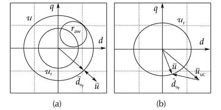
Fig.4 Definition of vectors
Proposition 1Consider the current subsystem and the corresponding controllerrespectively reported in the first equation of(1)and(11).Assumev(t)is always inside the interval specified in O2).
Then,if an anti-windup unit is defined exploiting the following elements:
.The additional reference dynamics

withKawan arbitrary symmetric Hurwitz matrix and
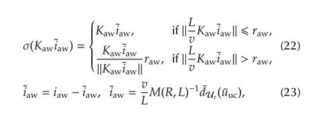
.The additional feedforward term(similar to what in(17))


then the following terms hold:

2)The additionalreference dynamics(21)is bounded.

4)The¯u(t)re-defined in(25)is in U,∀t.


4)By the definitions ofh1SAF,h2SAFin(21),the overall control action in(25)can be written as

and therefore,by(20)and(22),and the requirementraw∈[0,rin],the following inequality holds

which shows that the re-defined¯u(t)is always in U.□


Then,the termh2SAF,while improving the anti-windup dynamics convergence rate,gives an effective contribution in preserving good harmonic compensation capability.On the other hand,part of the control action,specifically the annulus of thicknessraw,has to be reserved for this suitably saturated “shaping”termh2SAF.Hence,a suitable trade-offbetween the anti-windup unit convergence property,and the loss of control authority,needs to be sought.

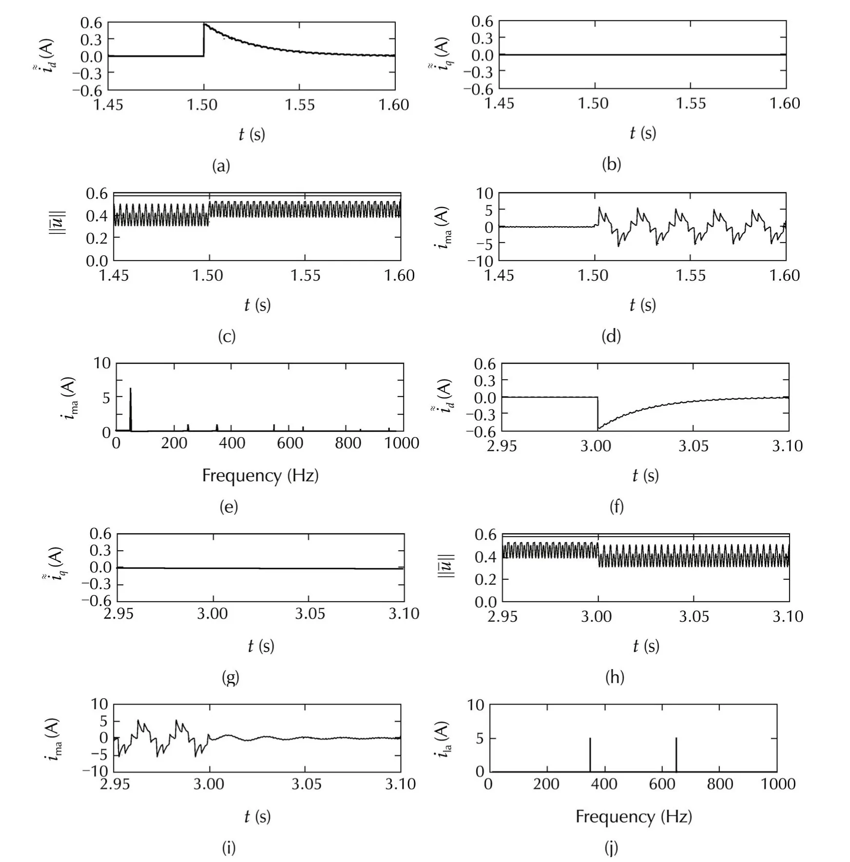
Fig.5 System performance under line voltage 20%increase in the interval[1.5,3]s,with the anti-windup solution:transition from nominal to saturation condition(a)–(d)and viceversa(f)–(i);and load harmonics(j)and mains current harmonics in the last 0.1 s of the line voltage increase interval(e).
Remark 4According to the general anti-windup strategy,the reference modification can act on both the active and reactive current components.The former could influence relevantly the DC-bus power flow[10,11],perturbing the action,η,of the adopted unconstrained voltage controller.This could impair the assumption of v(t)satisfying O2).
4.3 Improvements in the anti-windup strategy
In order to overcome the drawbacks arising from the straightforward application of the general strategy outlined in Section 4.1(see Remarks 3 and 4),and achieve objectives b)and d)stated in the Introduction,the design of the anti-windup dynamics is slightly modified,exploiting the properties of the specific system.The first step is to generate a reference modification acting only on the q current reference component,so that the antiwindup unit is,as much as possible,decoupled from the DC-link voltage dynamics and,as a consequence,it will minimally impair the voltage stabilizer action during saturation.To make the anti-windup dynamics(21)compliant with this restriction,the following distance vector is defined:


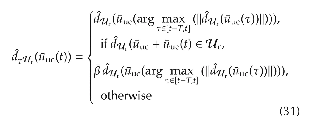


The positive effects of the proposed solution are shown in Fig.6.The simulation scenario is the same considered for Figs.3 and 5.Subplots(a),(b),(f)and(g)of Fig.6 are very similar to the counterparts in Fig.5,hence anti-windup performance has been preserved.A slight difference can be noted in plots(c)and(h),but the main point is the the shape of the current along the voltage increasing interval.Neglecting the initial and the final transients,it is a simple 50 Hz-sinusoid of reactive current as highlighted in plots(d),(i)and(e).Then,no additional harmonics are injected in the line grid,during this relevant line voltage transient.
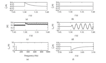
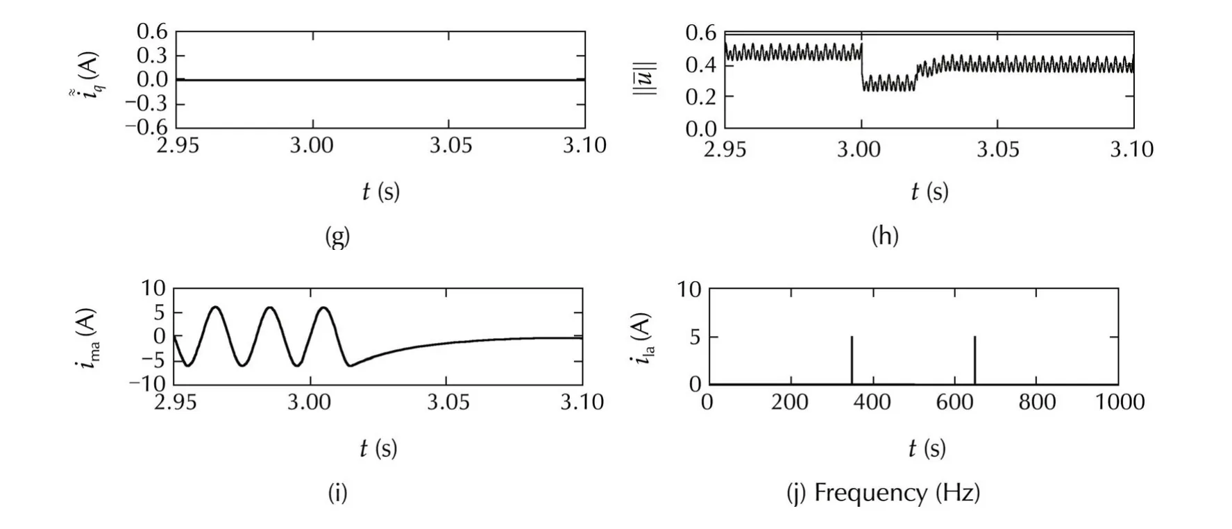
Fig.6 System performance under line voltage 20%increase in the interval[1.5,3]s,with the “improved”anti-windup solution(i.e.,with “almost constant”iawq and “almost null”iawd):transition from nominal to saturation condition(a)–(d)and viceversa(f)–(i);load harmonics(j)and mains current harmonics in the last 0.1 s of the line voltage increase interval(e).
In order to complete the simulation analysis,the test reported in Fig.6 has been repeated removing the correction on the anti-windup dynamics(i.e.,imposingraw=0 and,then,h2SAF(·)=0 in(21)).As expected,in Fig.7,it can be noted that the transients at the beginning and at the end of the voltage increase is clearly worse than the previous case.This points out the relevant contribution ofh2SAF= σ(Kaw˜iaw)in the test of Fig.6,even if at the cost of some margin to be saved in the control action(i.e.,raw>0)and with a little increase in¯iawq.
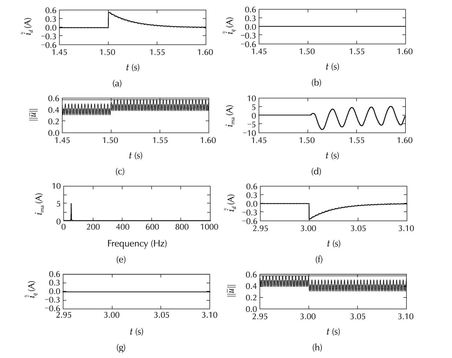

Fig.7 System performance under line voltage 20%increase in the interval[1.5,3]s,with the “improved”anti-windup solution(i.e.,with “almost constant”i awq and “almost null”i awd)but without the correction in i aw-dynamics(i.e.,r aw=0 and h2SAF=0):transition from nominal to saturation condition(a)–(d)and viceversa(f)–(i);load harmonics(j)and mains current harmonics in the last 0.1 s of the line voltage increase interval(e).
Next,an additionaltestisshown forthe complete antiwindup solution to underline the performance when a very large harmonic compensation is required(i.e.,larger than what unconstrained controller is designed for,according to considerations in Section 2.2).For this purpose,a benchmark load current profile,consisting of the first four harmonics of a diode bridge rectifier,is switched from a “feasible”size(i.e.,without any antiwindup strategy)to a larger value,in the time interval[1.5,3]s.


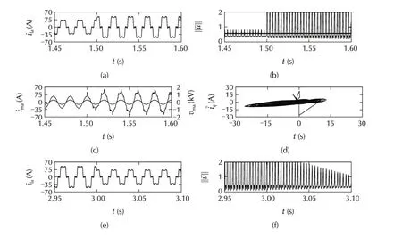

Fig.8 System performance with no anti-windup under off-nominal load harmonics in the interval[1.5,3]s:transition from nominal to overload condition(a)–(c)and viceversa(e)–(g);d-q current tracking errors phase portrait(d)and mains current harmonics in the last 0.1 s of the harmonic overload interval(h).
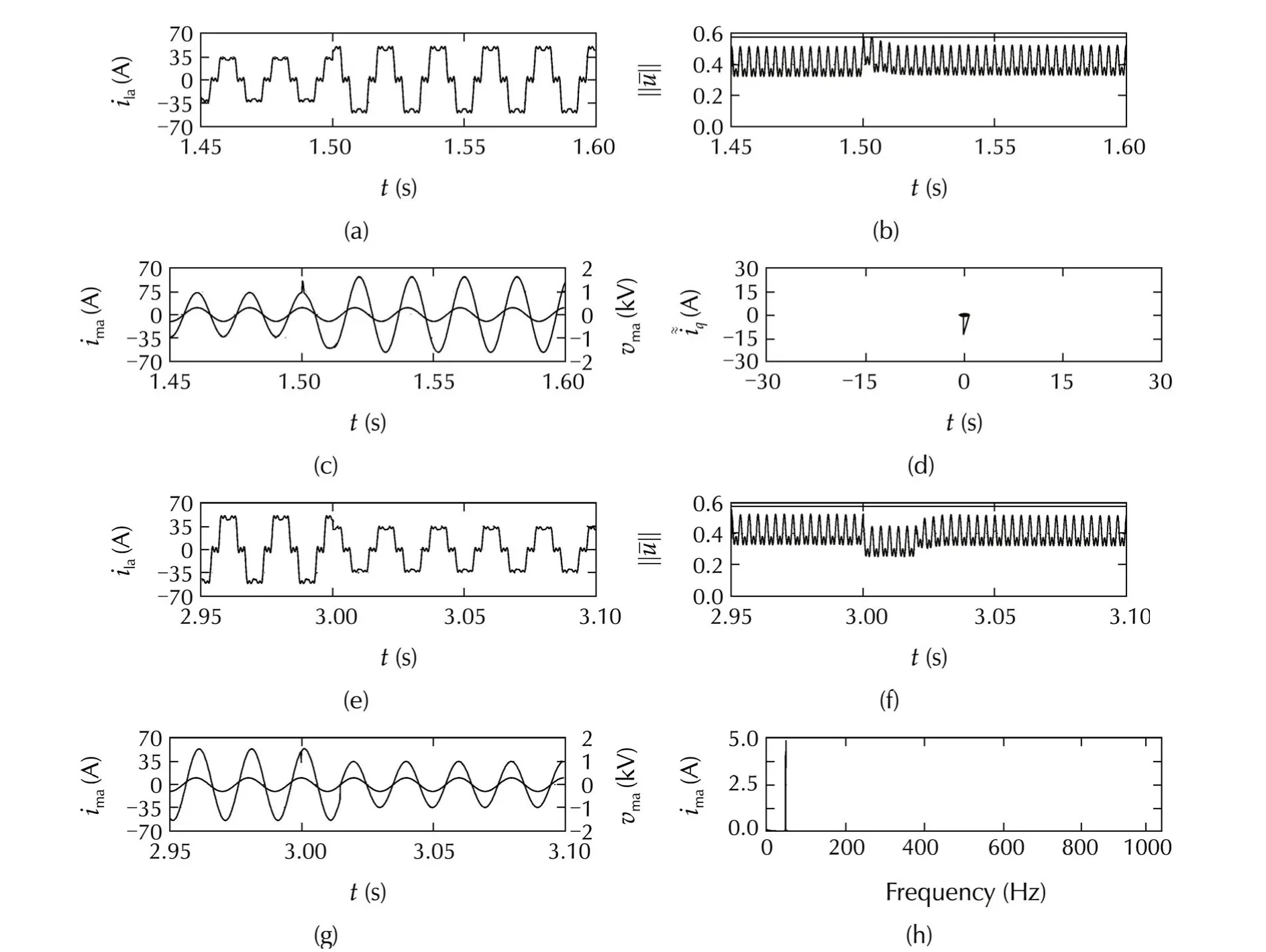
Fig.9 System performance with the proposed anti-windup under off-nominal load harmonics in the interval[1.5,3]s:transition from nominal to overload condition(a)–(c)and viceversa(e)–(g);d-q current tracking errors phase portrait(d)and mains current harmonics in the last 0.1 s of the harmonic overload interval(h).
5 Harmonic reference manager
The basic anti-windup solution for SAFs,presented in Section 4.2,can handle,in principle,any off-nominal condition by adding a suitable current reference.With the modifications added in Section 4.3,a better harmonics and DC-link management is guaranteed,but clearly some restrictions will arise on the set of attackable offnominal working conditions.In addition,limit on the maximum current amplitude have been neglected up to this stage,this will give additional restrictions,as well.In order to cope with such constraints,in this section,aharmonic reference manageris introduced to provide a suitable scaling of the harmonics to be compensated by SAF.The main idea is to reduce the harmonic compensation provided by SAF,whenever the working condition requires a control action which cannot be handled by the presented anti-windup approach,tacking into account current limits.
Next,the control voltage and the current limits are rewritten in order to underline the effects of the adopted anti-windup method.Then,an optimization problem is formulated and solved to derive the strategy for the proposed harmonic reference manager.The solution is carried out by exploiting some conservative approximations.This allows to get an effective and efficient solution,although at the cost of some optimality.
5.1 Current and control constraints with the proposed anti-windup unit
When the proposed anti-windup unit is combined with the current limits,inequality(6)is modified as


Regarding the control saturation,inequality(5),according to the definitions of Section 4,can be rewritten as


5.2 Optimization problem for harmonic reference scaling
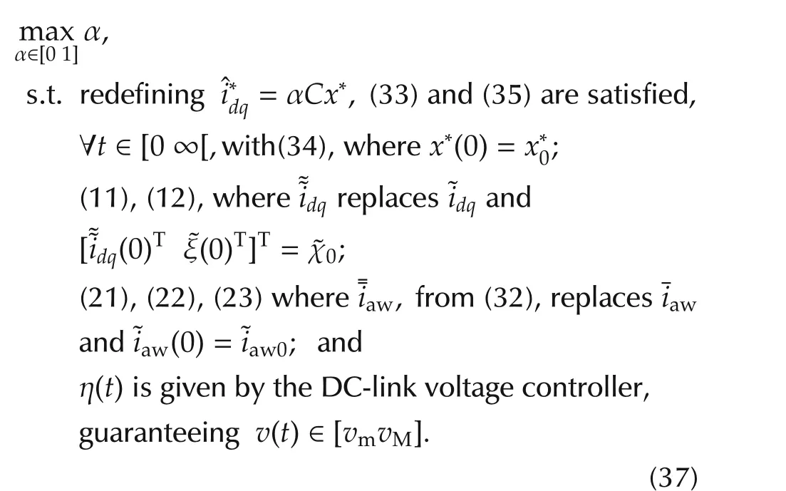
In order to scale the harmonic reference to comply with(33)and(35),the following optimization problem can be defined,where α is the scaling factor to be determined.

5.3 Reduced problem formulation


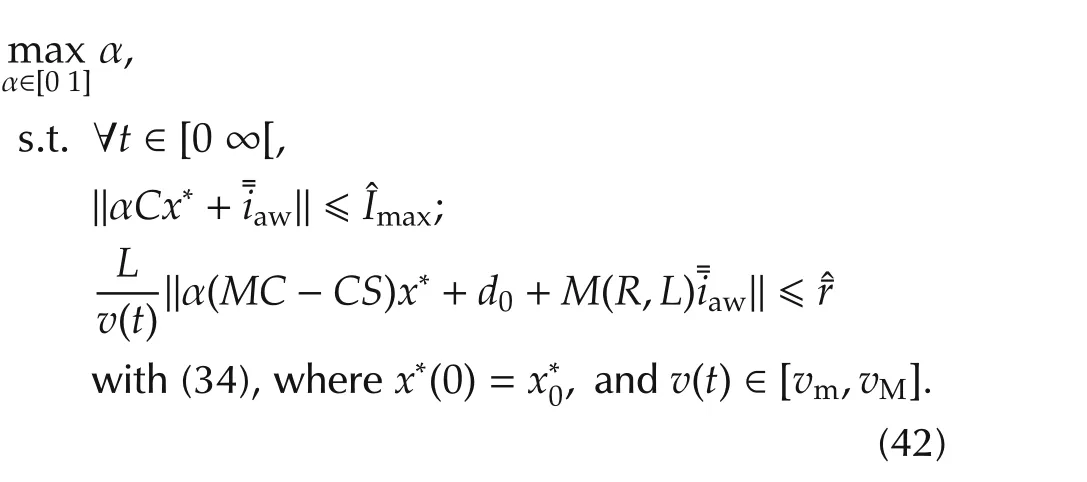

Fig.10 (a)Feasibility space with improved AW augmentation.(b)Control action devoted to DC-link voltage stabilization.(c)Vectorˆ¯u uc feasibility space.

5.4 Reduced problem solution and the resulting strategy


Then,the constraints considered in(42)can be replaced as follows,with some conservativeness:

Recalling(1),the definition of the anti-windup strategy in(32)and the definition of the euclidean norm,the second in(44)can be easily rewritten as


the discriminant of(47)is always positive,therefore:


5.5 Application to the considered case


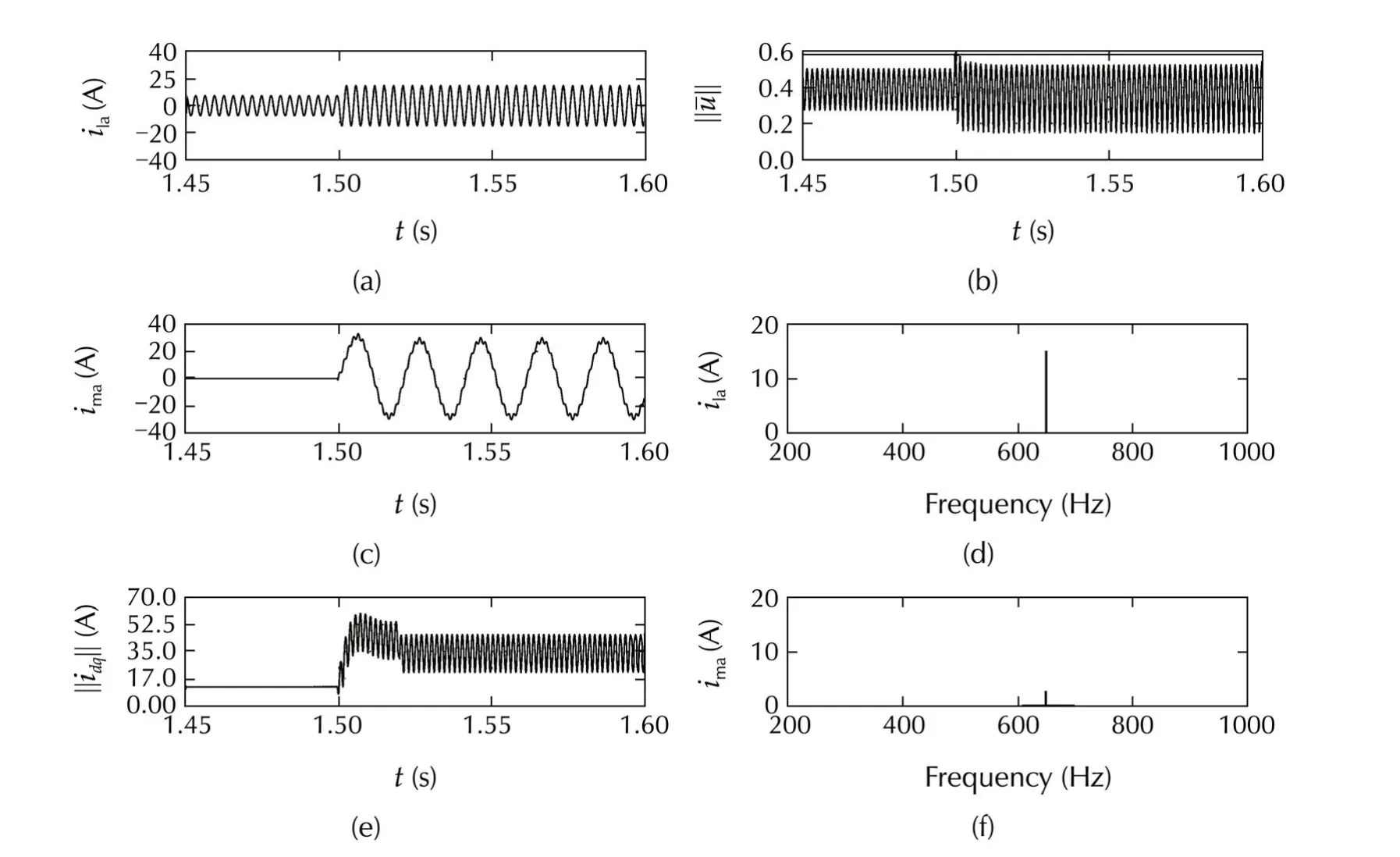
Fig.11 System performance with anti-windup unit and harmonic reference manager,under harmonic request exceeding the maximum from t=1.5 s:transition from nominal to overload condition(a);load current harmonic at t>1.5 s(d);control vector norm(b);SAF current norm(e);the resulting mains current(c)and mains current harmonics at t>1.55 s,the 50 Hz component has been removed to highlight the one at 650 Hz(f).
As expected,the current reference norm is limited to the maximum value compliant with the system constraint,hence,the harmonic is not completely canceled at the line side,as shown by the line current waveform and the corresponding magnitude spectrum.However,the strategy guarantees that the anti-windup system is able to keep the overall control action norm‖¯u‖within the admissible set,without injecting additional spurious components into the mains.Finally,it is wort noting that,in the proposed test,the maximum available SAF current,70 A is not actually reached,but just about 60 A have been exploited(see plot(e)of Fig.11).This difference gives a picture of the conservativeness introduced in the previous sections to find a simple solution(i.e.,with low run-time computational burden)of the problem(37).Indeed,the amount of“unexploited”current is not very large,tacking into account that 6.4 A are anyhow reserved for DC-link stabilization.
6 Conclusions
A plug-in unit has been developed to manage control saturation and current limit in SAFs,equipped with a controller designed under unconstrained scenario.This unit is composed by two main parts.First,an antiwindup scheme is added to the filter current controller,in order to prevent saturation of the system control voltage,relying on a dynamical correction of the current reference and a suitable feed-forward control action.The focus of the proposed approach is on the preservation of the original current error dynamics.This allows to save its stability and convergence properties,without any additional design or retuning.Besides this crucial property,the proposed anti-windup dynamics is shaped to improve the system cancellation performance under offnominal conditions,and not to impair the performance of DC-link voltage stabilizer.In addition,stabilization and converge properties of the proposed anti-windup dynamics have been addressed.With this anti-windup component at hand,the system current limitation is faced by designing a suitable harmonic reference manager,based on a proper scaling of the current reference according to the current working condition.This strategy is defined though the explicit solution to a suitable optimization problem.
With respect to common MPC and CG approaches,the presented method isspecifically tailored on SAFsand allows to obtain good performance with low computational burden,since no on-line optimization is required.
The proposed solution allows to cope effectively and efficiently with off-nominal events,as line overvoltages and harmonic overloads,with correct handling of control and current constraints.This gives a relevant improvementwith respectto standard SAF controlin terms of performance and affordable working conditions.But it is worth noting that the efficient management of current limits has required to save some conservative margins.In addition,correct DC-link voltage behavior has been assumed,relying on the large capacitance values,usually adopted in standard SAF dimensioning.Future efforts will be devoted to relax such assumptions in order to improve further the SAF features in off-nominal conditions.
Another point to be noted is the assumption of perfect knowledge of the SAF model adopted in designing the anti-windup unit.This is crucial to get exact decoupling with the original unconstrained control.If some model uncertainties were taken into account,additional tools,as Input-to-State Stability and SmallGain theorem,would be needed to address the feedback interconnection arising between the anti-windup dynamics and the original current error one.
[1] H.Akagi.New trends in active filters for power conditioning.IEEE Transactions on Industrial Applications,1996,32(6):1312–1332.
[2] B.Singh,K.Al-Haddad,A.Chandra.A review of active filters for power quality improvement.IEEE Transactions on Industrial Electronics,1999,46(5):960–971.
[3] N.Mohan,T.Undeland,W.P.Robbins.Power Electronics Converters,Applications and Design.New York:Wileyamp;Sons,1989.
[4] A.Chandra,B.Singh,K.A.Haddad.An improved control algorithm of shunt active filter for voltage regulation,harmonic elimination,power-factor correction and balancing of nonlinear loads.IEEE Transactions on Industrial Electronics,2000,15(3):495–507.
[5] S.G.Jeong,M.H.Woo.DSP-based active power filter with predictive currentcontrol.IEEE Transactions on IndustrialElectronics,1997,44(3):329–336.
[6] S.A.Verne,M.I.Valla.Active power filter with predictive current control of a diode clamped multilevel inverter.Proceedings of the 35th AnnualConference ofIEEE IndustrialElectronics,Piscataway:IEEE,2009:3211–3216.
[7]S.Rahmani,N.Mendalek,K.A.Haddad.Experimentaldesign ofa nonlinear control technique for three-phase shunt active power filter.IEEE Transactions on Industrial Electronics,2010,57(10):3364–3374.
[8] F.A.Okou,R.Beguenane,O.Akrif,et al.A multivariable adaptive nonlinear controller for a five-level diode-clamped active power filter.Proceedings of the American Control Conference,Los Alamitos:IEEE,2012:1460–1467.
[9] L.Marconi,F.Ronchi,A.Tilli.Robust perfect compensation of load harmonics in shunt active filters.Proceedings of IEEE Conference on Decision and Control,New York:IEEE,2004:2978–2983.
[10]L.Marconi,F.Ronchi,A.Tilli.Robust nonlinear control of shunt active filters for harmonic current compensation.Automatica,2007,43(2):252–263.
[11]A.Tilli,L.Marconi,C.Conficoni.Analysis,dimensioning and robust control of shunt active filter for harmonic currents compensation in electrical mains.Recent Advances in Robust Control-Theory and Applications in Robotics and Electromechanics,Croatia:Intech Open Access Publisher,2011:343–370.
[12]J.Liu,P.Zanchetta,M.Degano,et al.Control design and implementation for high performance shunt active filters in aircraft power grids.IEEE Transactions on Industrial Electronics,2012,59(9):3604–3613.
[13]B.Singh,J.Solanki.An implementation of an adaptive control algorithm for a three-phase shunt active filter.IEEE Transactions on Industrial Electronics,2009,56(8):2811–2820.
[14]J.Hanschke,L.Marconi,A.Tilli.Averaging control of the DC-link voltage in shunt active filters.Proceedings of IEEE Conference onDecision and Control,Piscataway:IEEE,2006:6211–6216.
[15]Z.Wang,C.Xie,J.Zhang,et al.Dynamic DC-bus voltage control strategies for a three-phase high power shunt active power filter.Proceeding of IEEE Applied Power Electronics Conference.New York:IEEE,2010:1514–1520.
[16]W.Guo,F.Lin,T.Zheng.Nonlinear pi control for three-phase PWM AC-DC converter.Proceedings of IEEE Industrial Electronics Conference.Piscataway:IEEE,2005:1093–1097.
[17]F.Ronchi,A.Tilli.Design methodology for shunt active filters.Proceedings of the 8th International Power Electronics and Motion Control Conference.2002:http://www-lar.deis.unibo.it/woda/data/deis-lar-publications/ea4a.document.pdf.
[18]E.G.Gilbert,I.Kolmanovsky.Fast reference governors for systems with state and control constraints and disturbance inputs.International Journal of Robust and Nonlinear Control,1999,9(15):1117–1141.
[19]D.Angeli,A.Casavola,E.Mosca.Command governors for constrained nonlinear systems:direct nonlinear vs.linearization based strategies.International Journal of Robust and Nonlinear Control,1999,9(10):677–699.
[20]A.R.Teel,N.Kapoor.TheL2anti-windup problem:Its definition and solution.Proceedings of the European Control Conference,Piscataway:IEEE,1997:1897–1902.
[21]A.R.Teel,N.Kapoor.Uniting local and global controllers.Proceedings ofIEEE Conference on Decision and Control,Piscataway:IEEE,1999:1214–1219.
[22]S.Galeani,S.Tarbouriech,M.C.Turner,et al.A tutorial on modern anti-windup design.European Journal of Control,2009,15(3/4):418–440.
[23]S.Tarbouriech,M.C.Turner.Anti-windup design:an overview of some recent advances and open problems.IET Control Theory Applications,2009,3(1):3–19.
[24]A.Tilli,C.Conficoni.Anti-windup scheme for current control of shunt active filters.Proceedings of the American Control Conference.Los Alamitos:IEEE,2012:6581–6587.
[25]L.Marconi,F.Ronchi,A.Tilli.Robust control of shunt active filter based on the internal model principle.Proceedings of the American Control Conference.New York:IEEE,2003:3943–3948.
[26]F.Ronchi,A.Tilli,L.Marconi.Control of shunt active filter based on the internal model principle:tuning procedure and experimental results.Proceedings of the European Control Conference.Stevenage:IEE,2003:2362–2367.
[27]H.Akagi,Y.Kanagawa,A.Nabae.Instantaneous reactive power compensator comprising switching devices without energy storage components.IEEE Transactions on Industry Applications,1984,20(11):625–630.
[28]L.Marconi,F.Ronchi,A.Tilli.Stabilization of the voltage internal dynamics of a shunt active filter.Proceedings of the 6th IFAC Symposium on Nonlinear Control Systems.Stuttgart:Institut fur Systemtheorie,2004.
[29]H.Khalil.Nonlinear Systems.3rd ed.Upper Saddle River:Prentice-Hall,2002.
[30]S.Boyd,L.E.Ghaoui,E.Feron,et al.Linear Matrix Inequalities in System and Control Theory.Philadelphia:SIAM,1994.
[31]T.Hu,A.R.Teel,L.Zaccarian.Stability and performance for saturated systems via quadratic and nonquadratic lyapunov functions.IEEE Transactions on Automatic Control,2006,51(11):1170–1786.
Appendix
In Section 5.3 reasonable bounds on the variables not directly related to the harmonics referencex∗,orthe anti-windup current term¯iaw,are assumed,in order to derive the reduced problem(42).The procedure to compute such elements is specified next.
A1 Evaluation of the current terms for DC-bus voltage stabilization
The bounds on the current term ηand its derivative,˙ηneeds to be set so that the DC-link voltage stabilizer is always able to achieve objective O2 defined in Section 2.1.In this regard,η should be large enough to match the quantity ϕ0,defined by(3),while˙η should be able to handle the voltage initial error.Bearing in mind these considerations,the maximum value of the variable η has to be set to satisfy the following inequality;ηmax≥kϕ0;wherek> 1 accounts for non steady-state conditions of the current and anti-windup sub-systems,and system parametric uncertainties,as it will be detailed later on.However,the power losses related component ϕ0depends on current drained by the filter(see equation(3)).Thus,the idea is to select ηmaxin order to maximize the current available for harmonic cancellation and anti-windup purposes,ensuring,at the same time,that the corresponding power losses related term ϕ0can be rejected by the saturated voltage stabilizer.


A2 Computation of upper bounds on the system error variables


Andrea TILLIis an associate professor at the Department of Electrical,Electronic and Information Engineering“Guglielmo Marconi”(DEI)of the University of Bologna.In 2000,he received the Ph.D.degree in System Science and Engineering from the same university.He is a member of the Center for Research on Complex Automated Systems “Giuseppe Evangelisti”(CASY),established within DEI.His current research interests include applied nonlinear control techniques,active power filters,wind turbines,electric drives for motion control and energy generation,thermal control of many-core systems-on-chip and supercomputers.E-mail:andrea.tilli@unibo.it.
†Corresponding author.
E-mail:christian.conficoni3@unibo.it.
©2015 South China University of Technology,Academy of Mathematics and Systems Science,CAS,and Springer-Verlag Berlin Heidelberg

the Master’s degree in Electronic Engineering,from the University of Bologna,Italy in 2008.In 2013,he
the Ph.D.degree in Automatic Control,from the same institution.Currently he is a post doctoral researcher at the Department of Electrical,Electronic and Information Engineering(DEI),at University of Bologna.His research interests include applied nonlinear control solutions for power electronic and electromechanical systems oriented to power quality enhancement,adaptive observers for electric drives sensorless operation,modeling and energy-oriented optimal thermal management of advanced computing platforms.E-mail:christian.conficoni3@unibo.it.
杂志排行
Control Theory and Technology的其它文章
- Distributed dynamic pricing based on demand-supply balance and voltage phase difference in power grid
- Decentralized load frequency control for two-area interconnected power system
- Simple adaptive air-fuel ratio control of a port injection SI engine with a cylinder pressure sensor
- Estimation and feedback control of air-fuel ratio for gasoline engines
- Gain-scheduling control of a floating offshore wind turbine above rated wind speed
- New adaptive vector control methods for induction motors with simpler structure and better performance
