Estimation and feedback control of air-fuel ratio for gasoline engines
2015-12-05MadanKUMARTielongSHEN
Madan KUMAR,Tielong SHEN
Department of Engineering and Applied Science,Sophia University,Tokyo,Japan
Received 29 October 2014;revised 31 March 2015;accepted 7 April 2015
Estimation and feedback control of air-fuel ratio for gasoline engines
Madan KUMAR†,Tielong SHEN
Department of Engineering and Applied Science,Sophia University,Tokyo,Japan
Received 29 October 2014;revised 31 March 2015;accepted 7 April 2015
In 4-stroke internal combustion engines,air-fuel ratio control is a challenging task due to the rapid changes of engine throttle,especially during transient operation.To improve the transient performance,managing the cycle-to-cycle transient behavior of the mass of the air,the fuel and the burnt gas is a key issue due to the imbalance of cyclic combustion process.This paper address the model-based estimation and control problem for cyclic air-fuel ratio of spark-ignition engines.A discrete-time model of air-fuel ratio is proposed,which represents the cycle-to-cycle transient behavior of in-cylinder state variables under the assumptions of cyclic measurability of the total in-cylinder charge mass,combustion efficiency and the residual gas fraction.With the model,a Kalman filter-based air-fuel ratio estimation algorithm is proposed that enable us to perform a feedback control of air-fuel ratio without using lambda sensor.Finally,experimental validation result is demonstrated to show the effectiveness of proposed estimation and control scheme that is conducted on a full-scaled gasoline engine test bench.
Discrete-time model,AFR estimation using Kalman filter,in-cylinder charge,combustion efficiency,PI controller
DOI 10.1007/s11768-015-4148-9
1 Introduction
In the last several decades,the performance of the combustion engines is focused on the optimization of fuel efficiency and emissions due to the limitation of sources of fuel and environmental aspects.The cyclic fluctuation in combustion engines is an important fact thataffects the engine performances,such as the air-fuel ratio and torque generation,since the cyclic variation of the residual burnt gas,the unburnt fuel and the unreacted air succeeding the next cycle from previous cycle effect to the cyclic combustion quality[1,2].However,the combustion event in-cylinder is a complex phenomena and is difficult to analyze on cyclic basis due to the high pressure,temperature variation and gas exchange dynamics during cycles.Moreover,the combustion event exhibits stochastic characteristics.
In the research field of stochastic variation,several investigations based on experimental and physical models have been introduced,such as experimental study of cyclic combustion variation as reflected in the maximum pressure,indicated mean effective pressure,anddynamic injection timing[3–5].The stochastic modelfor the cyclic combustion variation and prier-cycle effects considering the in-cylinder residual gas contents[6–9].
To challenging the air-fuel ratio(AFR)control problems,several researches have been reported,such as AFR using model predictive control based on a neural network model in real time to cope with nonlinear dynamics[10].In[11],AFR control at desired target level based on multi-input-multi-output sliding mode control scheme to simultaneously control the mass flow rate of both port and direct fuel injection systems with guaranteed stability to drive the system AFR under various air flow disturbances is reported.AFR control based on stochastic L2disturbance attenuation with considering the residual gas fraction as a stochastic process with Markovian property is discussed in[12].Control of AFR based on adaptive control approach of time delay systems in which adoptive posicast controller has been developed that used adaptation in both feedforward and feedback paths[13].Linear quadratic tracking control forAFR based on a control-oriented modelduring engine transient operation is presented in[14].Usually,these air-fuel control applications are based on lambda-sensor which is equipped on the exhaustmanifold.Thereforthe combustion-to-exhaust delay and the transient dynamics of the sensor constraint the performance of air-fuel control,specially during transient operating mode.
Recently,in-cylinder pressure-based air-fuel ratio estimation method is proposed to cope with the sensing delay.In the literature[15],the estimation of instantaneous AFR using the in-cylinder pressure signal in which the advantage of linear relation between AFR and the 2nd or the 3rd order moment of pressure cycle has been considered and then a simple regression model and its identification is proposed and[16]presented a model and identification based on net heat releases profile using in-cylinder pressure signal for cyclic averaging AFR,but still variance of the estimates is larger which need to be improved.In recenttrends researchers are getting almost information of engine behavior using the advantage of in-cylinder pressure data,which is fast in response in transient mode.An investigation of feedback signal based on in-cylinder pressure can be seen in[17,18].Since the in-cylinder contents such as in-cylinder air,fuel and residual gas compositions are difficult to measure directly except in-cylinder pressure data,a model based observer is thus necessary to estimate these quantities for the analysis of in-cylinder cyclic variation of contents and control application in transient mode.
In this paper,a discrete-time model and control system for air-fuel ratio that represents the cyclic transient behaviorofin-cylinderstate variables underthe assumptions ofmeasurability ofthe cyclic totalin-cylindermass,residualgasfraction and combustion efficiency using the in-cylinder pressure data is proposed.The control system is modeled as a time-varying linear system as the state variables are considered as total fuel mass,residual unreacted air and burnt gas mass.The Kalman filter algorithm is used for the estimation of these state variables and a PI feedback controller approach is used for the control of air-fuel ratio to desired value.Validation of model and control system for air-fuel ratio have been done in steady and transient mode of experiments on a gasoline engine test bench.
2 Experimental setup and measurement
2.1 Experimental setup
In this research work,a gasoline direct injection(GDI)engine(Engine type:2 GR-FSE,V6,3.5 L(TOYOTA))is used for the experiment and analysis.The engine specifications are given in Table 1.Engine is coupled to a HORIBA made low inertial dynamometer as shown in Fig.1.The engine is facilitated by direct and port fuel injection which can be switched automatically on operating conditions.The engine is well instrumented for the analysis and control of engine systems.Variable valve timing(VVT)system is also in-built for the analysis of the effect of VVT on the in-cylinder gas contains,such as residual gas mass during cyclic fluctuation.The dSPACE(DS1106)and electronic control unit(ECU)are used for the capturing of data and control input,such as of throttle position,fuel injection,spark advance and VVT.An interface system is used to avoid the signal delay in connecting area network(CAN).In addition,forthe analysis of desired experiment and study,additional sensors are also installed in the engine,such as individual cylinder air-fuel ratio sensor,intake port temperature sensor,NOx sensor and manifold pressure sensor.Apart from these,a separate combustion analyzer(Aamp;D)is also used for the heat release rate and combustion efficiency analysis simultaneously.
In this experimental setup,the data of total in-cylinder charge,combustion efficiency and residual gas using incylinder pressure data in real time experiment are captured with the help of simulink program for the 5th cylinder.
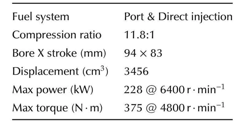
Table 1 Engine specifications.
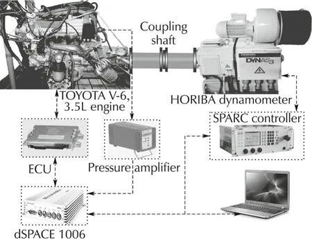
Fig.1 Experimental setup.
2.2 Pressure sensor based measurement
In-cylinder cyclic total charge Mtp(k)is calculated in real time experiment using the in-cylinder pressure data[15,19]as given below:

where P and V denote the in-cylinder pressure and volume,respectively.ΔP is the pressure difference between pressure P2(k)and P1(k).P1(k)and V1(k)data are considered at 5°crank angle after intake valve closure(aIVCi).P2(k)and V2(k)data are considered at 45°crank angle after intake valve closure(aIVCi)during the compression stroke for maintaining the adiabatic polytropic process.n is the polytropic constant and assumed constant value(1.32).T1is in-cylinder gas temperature(assumed engine warmed temperature)and R is the universal gas constant.
The residual gas fraction r(k)at the end of exhaust stroke is calculated using in-cylinder pressure data is as given in equation(2)[1].

where P3(k)and V3(k)data are considered at5°crank angle before exhaust valve open(bEVOe).P4(k)and V4(k)data are considered at 5°crank angle before exhaust valve closure(bEVCe)for avoiding the signal response delay and fluctuation in signals due to mechanical systems.A cyclic process for measurement points for the total charge and residual gas fraction are shown in Fig.2.
Similarly,the combustion efficiency Cf(k)on cycle basis is also calculated using the ratio of total heat release during the cycle and the energy contained in the fuel injected as given below.
The heat release is calculated using the thermodynamics heat release model[20]given in equation(3).The heat transfer from the wall and lubricant oil is not taken in account for avoiding the computational load.

The fuel energy calculated as

Hence from equations(3)and(4),the combustion efficiency(Cf(k))in on-line experiment can be calculated on cycle basis as

where st.comb.,EVO and LHV denotes the start of combustion,exhaust valve opening and the lower heating value of fuel,respectively.
For the validation of total charge mass calculated using the signal from pressure sensor,a reference value of total charge mass is also calculated using the direct measurement of air mass,fuel mass form sensor and calculated RGF based on pressure data and results of total charge using both methods have been compared.The direct measurement of fresh inducted air,fresh injected fuel and RGF using in-cylinder pressure data are used to calculated the total mass in direct measurement as given below:

where mind(k−1)and uf(k−1)denotes the fresh inducted air and injected fuel respectively from the previous cycle for the combustion of present cycle on the basis of cycle definition as shown in Fig.2.
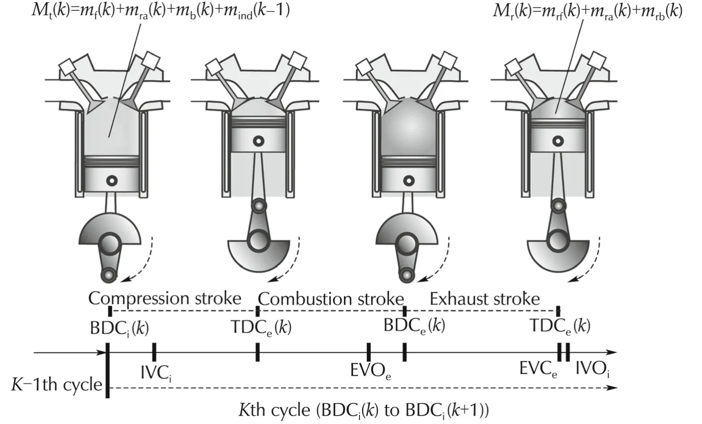
Fig.2 Cyclic gas exchange definition.
2.3 Problem descriptions
As it is well known that the AFR is the most affecting source for the automotive performance.Thus,our main aim is to develop a model which can display the transient AFR estimation and its control with negligible delay in signals.In this work,a discrete time model is developed assuming the in-cylinder state variables such as in-cylinder total fuel mf,residual air mraand burnt gas mb.These state variables are estimated using the Kalman filter estimation method.The input variables for the model and state estimation have been used as fresh injected fuel,inducted airmass,residualgasfraction and combustion efficiency.After estimating the state variables,the in-cylinder AFR is calculated using same state variables and comparison has been done with AFR measured by lambda sensor.The estimated AFR is then controlled to a reference value(stoichiometric AFR(14.6))using feedback PI controller.The input control is considered as direct fuel injection uf.
3 Modeling and estimation
The model is developed on the basis of the cycle definition from BDCi(k)to BDCi(k+1)as k th cycle as shown in Fig.2.In this cycle,data at BDCi(k)is considered in k th cycle and data at BDCi(k+1)is considered in k+1th cycle.Next cycle(k+1th cycle)variables can be estimated from the present cycle(k th cycle)variables using this model.From Fig.2,it can be state that the total mass of the charge Mt(k)including fresh charge of present cycle and residual burnt gas mass,unreacted air and unburnt fuel mass from previous cycle will have contribution in the combustion performance of present cyclic process.
3.1 Modeling
The in-cylinder total mass Mt(k)for the combustion in one cycle includes the total fuel,unreacted air,burnt gas and fresh inducted air mass which is represented as

For the sake of simplicity during the model derivation,two assumptions have been considered as follows:
1)Mass is conserved during the gas exchange in cyclic process.
2)The fraction of residual air,residual fuel and residual brunt gas of a cycle are all assumed to be equivalent.

On the basis of cycle definition in Fig.2 and the above assumptions,the total mass of fuel,mass of unreacted air(residual air)and residual burnt gas for the next cycle combustion(i.e.,k+1th cycle)are derived as:
a)From the mass conservation law,the total mass of fuel available for start of combustion in k+1th cycle is equal to the summation of mass of unburnt fuel in k th cycle and fresh fuel injected at the start of k+1th cycle which is considered in k th cycle as defined in cycle definition Fig.2.Hence,the total fuel in k+1th cycle can be written in mathematical form as

If the combustion efficiency Cf(k)and residual gas fraction r(k)on cycle basis are measurable,then the unburnt fuel which is available for k+1th cycle from k th cycle will be equal to(1−Cf(k))r(k)mf(k).Hence,after substituting unburnt fuel in terms of Cf(k)and r(k),the total fuel for the k+1th cycle can be written as

b)The unreacted air(residual air)at the start of combustion in k+1th cycle is equal to the residual air which is trapped in cylinder at the end of k th cycle.This unreacted air can be calculated in terms of combustion efficiency and RGF as:
Total air mass before start of combustion in k th cycle is the summation of unreacted air mass(mra(k))and fresh inducted air mass(mind(k−1)).When combustion starts,the λdCf(k)mf(k)amount of air mass will consumed during the combustion.Hence,the residual air mass can be obtained by the multiplication of RGF(r(k))in total air mass available excepting the air mass which has been consumed in combustion process as

After simplification,the model for unreacted air mass becomes as

c)Similarly,the burnt gas at the start of combustion in k+1th cycle is equal to the residual burnt gas at the end of k th cycle.This burnt gas will be equal to the summation of the residual burnt gas from previous cycle and burntgas contributed by airand fuelduring combustion.The burnt gas in term of combustion efficiency and RGF can be written as

After simplification,the model for burnt gas becomes as

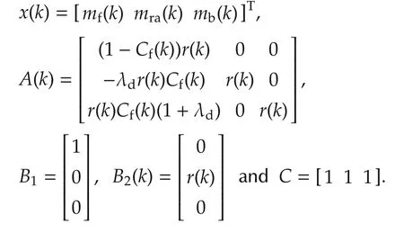
where mf(k)denotes the mass of total fuel(=uf(k−1)+mrf(k−1))in the cycle at the start of combustion,mrfis unburnt fuel from previous cycle which is available for the combustion in presentcycle,Cf(k)is the combustion efficiency,uf(k)is fresh fuel injected,r(k)is residual gas fraction(RGF),mra(k)is unreacted air mass,λdis the stoichiometric air fuel ratio(14.6),mb(k)is the mass of burntgas and mind(k−1)is fresh airwhich is considered in previous cycle on cycle definition in Fig.2.
For the modeling and control system of air-fuel ratio,two assumptions are considered for the sake of simplicity as follows:

Then finally,discrete time model for estimation of cyclic behavior is represented as

where Δ is constant and measured by the air mass flow sensor,ζ(k)is variance(ζ(k)∈ N(0,σ2).Mt(k)is the total mass of charge in cylinder which is measured using the in-cylinder pressure data as discussed in Section 2.2.ξ(k)is the measurement noise,x(k)is the state variables and A(k),B1,B2(k)and C are constants as given below:
3.2 Estimation using Kalman filter
For the estimation of in-cylinder state variables,a Kalman filter algorithm is used for the same model.
Estimated variables and control output for the air-fuel control system using the Kalman filter estimation are written as

The Kalman filter gain is calculated as given below:

whereL(k)denotes the Kalman filter gain which can be calculated using equation(16).PwandPvare assumed to be covariance of process and sensor white noise respectively as Gaussian random process with zero mean.ymes(k)is measured from the experiment andˆy(k)is estimated from the Kalman filter.
4 AFR feedback control design
AFR is estimated by the Kalman filter method using the input variables as fresh fuel injected,inducted air,residual gas fraction and combustion efficiency.A feedback PI controller is designed for the AFR control.The estimated AFR from equation(17)is controlled at desired reference value(Ref.(14.6)).The input control for AFR is used as direct fuel injection(uf).A schematic diagram for estimation and feedback control is shown in Fig.3.

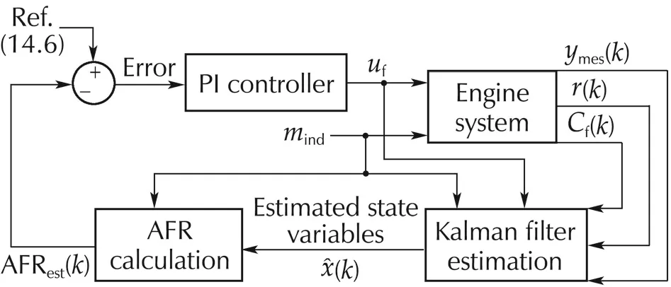
Fig.3 Kalman filter estimation and feedback PI control schematic block diagram.
5 Validation
5.1 Model validation
Model validation is done in off-line simulation and real time experiment using total in-cylinder charge measured by both methods(i.e.,measured by directly sensor(Mts(k))and calculated by pressure data(Mtp(k)).In simulation,actual experimental data such as fresh inducted air,fuel injected,total in-cylinder charge,residual gas fraction and combustion efficiency on cycle basis are used as input variables.
5.1.1 Model validation using Mts(k)
In this case,ymes(k)is calculated from equation(18)and AFRmeas(k)is measured by lambda sensor and then comparison has been done with model result as shown in Fig.4.In graph,it is shown that the simulation result of control outputy(k)and AFR are able to approach the measured result and the delay in signals is found approximately 0.25 ms which is equal to one simulation sampling time.

whereMts(k)is calculated from equation(6)and Δ measured from air mass flow sensor.
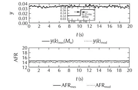
Fig.4 Comparison ofsimulation resultofmodeland measured control output and AFR using Mts(k).
5.1.2 Model validation using Mtp(k)
In this case,ymes(k)is calculated from equation(19)and AFRmeas(k)is measured from sensor and then comparison has been done with model result as shown in Fig.5.
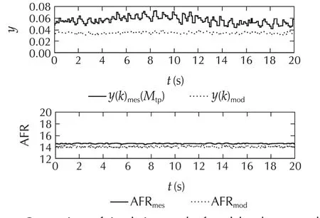
Fig.5 Comparison ofsimulation resultofmodeland measured control output and AFR using Mtp(k).
It is observed that,the results in this case contain more noise and some offset compared to previous case.The noise exhibits due to high cyclic fluctuation in the in-cylinder pressure data,which is mainly caused due to the combustion phenomena in cylinder.The offset ap-pears due to the model assumptions and measurement process of model input variables.

where Mtp(k)and r(k)are calculated from equation number(1)and(2),respectively.mfn(k−1)is measured by the fuel sensor.
5.2 Experimental validation


Remark 1The estimated AFR shows faster response than lambda sensor,because the estimated AFR has been estimated by Kalman filter algorithm(assuming the process and measurement noise as Gaussian white noise)using the in-cylinder pressure signal which gives faster signal response compared to the lambda sensor signal.The offset between AFR results improved due to considering in account of the contribution of residual air and residual fuel.
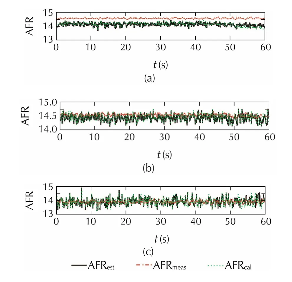
Fig.6 Comparison of estimated measured AFRmeas by lambda sensor at(a)1000 r·min−1,60 N·m,(b)1000 r·min−1,120 N ·m,and(c)1000 r·min−1,180 N·m in steady state experiment.
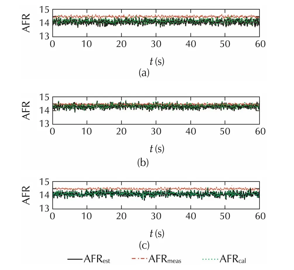
Fig.7 Comparison of estimated measured AFRmeas by lambda sensor at(a)2000 r·min−1,60 N·m,(b)2000 r·min−1,120 N ·m,and(c)2000 r·min−1,180 N·m in steady state experiment.
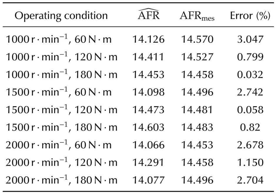
Table 2 Estimated mean AFR and its offset from measured by lambda sensor.
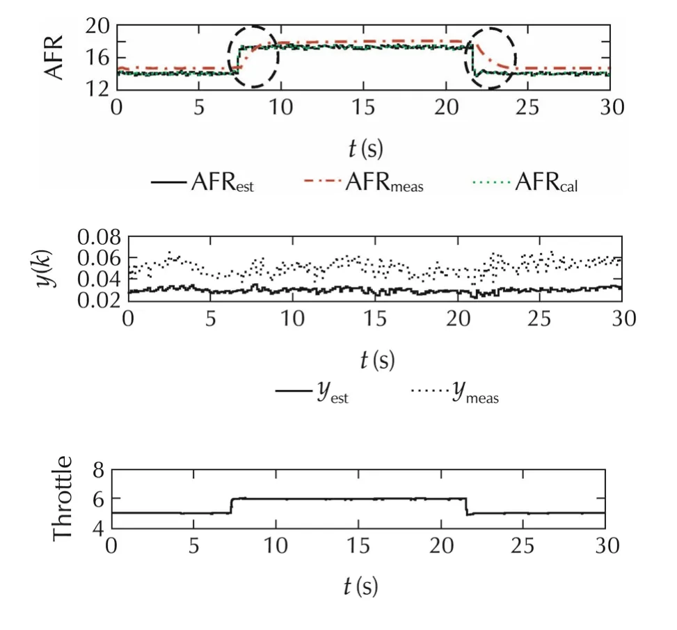
Fig.8 Comparison of estimated by Kalman filter and measured AFRmeasby lambda sensor in transient mode experiment.
5.3 Validation of AFR feedback control
A feedback PI control approach is implemented to controlAFRusingtheKalmanfilterbasedestimatedstate variables.The response of PI control is also analyzed by the changes of desired value(reference)of AFR keeping the throttle constant.A graph of transient AFR(desired value)to observe the control response time is shown in Fig.9.It is shown that the PI controller is able to control AFR after some delay of time(approximately 1.5s).The experimental results of AFR control at different operating conditions to verified the AFR control approach are indicated by circles which shown in Figs.10 and 11.These results indicate that the estimated AFR and its control using the in-cylinder pressure data can give faster response with negligible delay in feedback signals compared to lambda sensor which fulfill the research objective of several researchers.
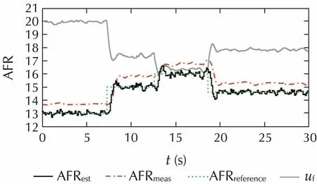
Fig.9 PI control response by changes of desired reference AFR.
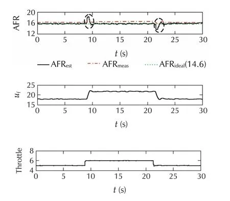
Fig.10 PI feedback control of AFR at 1000r·min−1,60N·m.
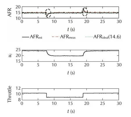
Fig.11 PI feedback control of AFR at 2000r·min−1,96N·m.
6 Conclusions
A discrete-time model is developed that represents the cycle-to-cycle transient behavior of the total mass of fuel,unreacted air and residual gas.As an application of the proposed model,Kalman filter-based estimation algorithm is proposed under the assumption that the stochastic property of cyclic variation of the combustion efficiency and the residual gas fraction are Gaussian process.It should be noted that the measurement of cyclic total in-cylinder charge,combustion efficiency and residual gas fraction is still a challenging task due to the cyclic imbalances and if the noise does not satisfied the assumptions of stochastic properties and changes according to operating mode,then some correction is needed in model for implementation on different systems.
Acknowledgements
The authors wish to thanks to Toyota Motor Corporation for the supporting this research and valuable discussion and Mr.Mingxin Kang for helping in conducting the experiment.
[1]J.Yang,T.Shen,X.Jiao.Model-based stochastic optimal air-fuel ratio control with residual gas fraction of spark ignition engines.IEEE Transactions on Control Systems Technology,2013,22(3):896–910.
[2]D.Clerk.The Gas Engine.1st ed.New York:Longmans,Green and Co.,1886.
[3]D.C.Rakopoulos,C.D.Rakopoulos,E.G.Giakoumis,et al.Studying combustion and cyclic irregularity of diethyl ether as supplement fuel in diesel engine.Fuel,2013,109:325–335.
[4]M.Reyes,F.V.Tinaut,B.Gimenez.Characterization of cycle-tocycle variations in a natural gas spark ignition engine.Fuel,2015,140:752–761.
[5]D.C.Rakopoulos,C.D.Rakopoulos,E.G.Giakoumis,et al.Experimental-stochastic investigation of the combustion cyclic variability in HSDI diesel engine using ethanol-diesel fuel blends.Fuel,2008,87(8):1478–1491.
[6]C.S.Daw,C.E.A.Finney,J.B.Green,et al.A Simple Model for Cyclic Variations in a Spark-ignition Engine.SAE Technical Paper 962086.1996:DOI 10.4271/962086.
[7]C.S.Daw,C.E.A.Finney,M.B.Kennel,et al.Observing and modeling nonlinear dynamics in an internal combustion engine.Physical Review E,1998,57(3):2811–2819.
[8]G.Rizzoni.A stochastic model for the indicated pressure process and the dynamics of internal combustion engine.IEEE Transactions on Vehicular Technology,1989,38(3):180–192.
[9]J.B.Vance,B.C.Kaul,S.Jagannathan,et al.Output feedback controller for operation of spark ignition engines at lean conditions using neural networks.IEEE Transactions on Control Systems Technology,2008,16(2):214–228.
[10]S.Wang,D.Yu,J.B.Gomn,et al.Adaptive neural network model based predictive control of an internal combustion engine with a new optimisation algorithm.Proceedings of the Institution of Mechanical Engineerings–Part D:Journal of Automobile Engineering,2006,220(2):195–208.
[11]S.Pace,G.Zhu.Sliding mode control of a dual-fuel system internal combustion engine.Proceedings of the ASME Dynamic systems and Control Conference.New York:ASME,2010:881–887.
[12]J.Yang,T.Shen,X.Jiao.Air-fuel ratio control with stochasticL2disturbance attenuation in gasoline engines.Journal of Control Theory and Applications,2013,11(4):586–591.
[13]Y.Yildiz,A.M.Annaswamy,D.Yanakiev,et al.Spark ignition engine fuel-to-air ratio control:an adaptive control approach.Control Engineering Practice,2010,18(12):1369–1378.
[14]S.Pace,G.Zhu.Transient air-to-fuel ratio control of an spark ignited engine using linear quadratic tracking.Journal of Dynamic Systems Measurement and Control,2014,136(2):DOI 10.1115/1.4025858.
[15]I.Arsie,D.L.Rocco,C.Pianese,et al.Estimation of in-cylinder mass and AFR by cylinder pressure measurement in automotive Diesel engines.Proceedings of the 19th IFAC World Congress.Cape Town,South Africa:IFAC,2014:11836–11841.
[16]P.Tunestl,J.K.Hedrick.Cylinder air/fuel ratio estimation using net heat release data.Control Engineering Practice,2003,11(3):311–318.
[17]G.W.Pestana.Engine Control Methods Using Combustion Pressure Feedback.SAE Technical Paper 890758,1989:DOI 10.4271/890758.
[18]P.Wibberley,C.A.Clark.An Investigation of Cylinder Pressure as Feedback for Control of Internal Combustion Engines.SAE Technical Paper 890396,1989:DOI 10.4271/890396.
[19]J.M.Desantes,J.Galindo,C.Guardiola,et al.Air mass flow estimation in turbocharged diesel engines from in-cylinder pressure measurement.Experimental Thermal and Fluid Science,2010,34(1):37–47.
[20]J.B.Heywood.Internal Combustion Engine Fundamentals.New York:Mcgraw-hill,1988.

the M.Sc.degree from Indian Institute of Technology Madras,India,in 2014.He is currently pursuing the Ph.D degree with the Department of Mechanical Engineering,Sophia University,Tokyo,Japan.His current research interests include cyclic control of air-fuel ratio,residual gas fraction and NOx emission control.E-mail:madanbhuit.10@gmail.com.
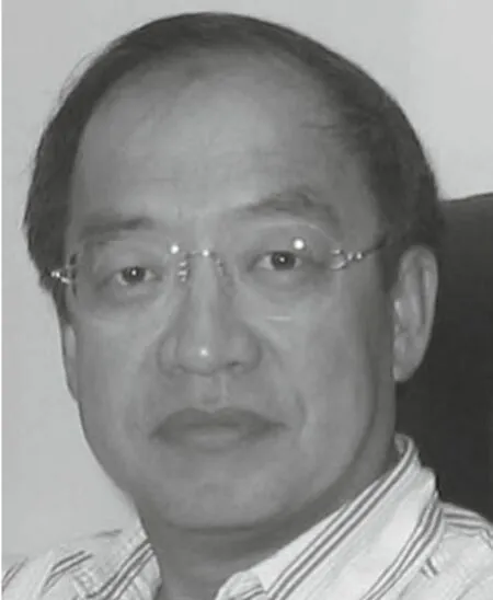
Tielong SHENreceived the Ph.D.degree in Mechanical Engineering from Sophia University,Tokyo,Japan,in 1992.He has been a faculty member with the Department of Mechanical Engineering,Sophia University,since 1992,where he currently serves as a professor with the Department of Engineering and Applied Sciences.His current research interests include control theory and application in mechanical systems,power systems,and automotive power train.E-mail:tetu-sin@sophia.ac.jp.
†Corresponding author.
E-mail:madanbhuit.10@gmail.com.
©2015 South China University of Technology,Academy of Mathematics and Systems Science,CAS,and Springer-Verlag Berlin Heidelberg
杂志排行
Control Theory and Technology的其它文章
- Distributed dynamic pricing based on demand-supply balance and voltage phase difference in power grid
- Decentralized load frequency control for two-area interconnected power system
- Increasing the operating area of shunt active filters by advanced nonlinear control
- Simple adaptive air-fuel ratio control of a port injection SI engine with a cylinder pressure sensor
- Gain-scheduling control of a floating offshore wind turbine above rated wind speed
- New adaptive vector control methods for induction motors with simpler structure and better performance
