Simple adaptive air-fuel ratio control of a port injection SI engine with a cylinder pressure sensor
2015-12-05ChanyutKHAJORNTRAIDETKazuhisaITO
Chanyut KHAJORNTRAIDET ,Kazuhisa ITO
1.Graduate School of Engineering and Science,Shibaura Institute of Technology,Saitama 337-8570,Japan;
2.Department of Machinery and Control Systems,College of Systems Engineering and Science,Shibaura Institute of Technology,Saitama 337-8570,Japan
Received 29 October 2014;revised 19 March 2015;accepted 20 March 2015
Simple adaptive air-fuel ratio control of a port injection SI engine with a cylinder pressure sensor
Chanyut KHAJORNTRAIDET1†,Kazuhisa ITO2
1.Graduate School of Engineering and Science,Shibaura Institute of Technology,Saitama 337-8570,Japan;
2.Department of Machinery and Control Systems,College of Systems Engineering and Science,Shibaura Institute of Technology,Saitama 337-8570,Japan
Received 29 October 2014;revised 19 March 2015;accepted 20 March 2015
The problem of air-fuel ratio(AFR)control of the port injection spark ignition(SI)engine is still of considerable importance because of stringent demands on emission control.In this paper,the static AFR calculation model based on in-cylinder pressure data and on the adaptive AFR control strategy is presented.The model utilises the intake manifold pressure,engine speed,total heat release,and the rapid burn angle,as input variables for the AFR computation.The combustion parameters,total heat release,and rapid burn angle,are calculated from in-cylinder pressure data.This proposed AFR model can be applied to the virtual lambda sensor for the feedback control system.In practical applications,simple adaptive control(SAC)is applied in conjunction with the AFR model for port-injected fuel control.The experimental results show that the proposed model can estimate the AFR,and the accuracy of the estimated value is applicable to the feedback control system.Additionally,the adaptive controller with the AFR model can be applied to regulate the AFR of the port injection SI engine.
Spark ignition engine,in-cylinder pressure,simple adaptive control,air-fuel ratio estimation and control
DOI 10.1007/s11768-015-4149-8
1 Introduction
The air-fuel ratio(AFR)control has been developed and improved because of demands on increased engine efficiency and emission control.For pollution control,the AFR in the combustion chamber has to vary within a very narrow range[1].The possibility of sensing the AFR plays an important role in the determination of the fuel injection control strategy.In practical applications,the in-cylinder pressure has been considered as a dominant indicator of combustion performance in internal combustion engines.Therefore,the combustion control and analysis can be performed on the basis of in-cylinder pressure data.In many studies,in-cylinder pressure is utilised for combustion analysis and control of spark ignition(SI)engines[2–5].There are many combustionparameters that can be obtained from cylinder pressure data,such as the heat release rate,total heat release,and the rapid burn angle,for example[6].The calculation of these combustion parameters requires accurate in-cylinder pressure and crank angle data in practice.For instance,the inaccurate crank angle data leads to an incorrect heat release rate and to an incorrect magnitude of the total heat release calculation[7].The control system using combustion pressure measurementcan be used under cold or lean conditions when the conventionalexhaustgas oxygen sensorcannotbe used[8].The AFR can be calculated from in-cylinder pressure data using an empirical model accounting for the dependence of the laminar flame speed on temperature,pressure,and AFR[9].The model parameters are obtained from a steady state experiment at different loads,speeds,and AFR.The linear least-squares regression is used to compute the model parameters for minimisation of the sum of the squares of the residuals between the measured and the estimated AFR[10].Many approacheshave been developed for determining the relationship between the cylinder pressure and the in-cylinder AFR for the estimation of the cylinder pressured-based AFR.These include,for example,the cylinder pressure moment approach[11],the molecular weight approach[12],and the equivalent heat release duration approach[13].The challenging target of the in-cylinder pressure-based AFR calculation isitsapplication to feedback controlsystems.
The main difficulties in the design ofthe AFR controller include the variable time delays and the uncertain plant behaviours and disturbances[14].The model reference adaptive control(MRAC)has a high efficiency in the controlofthe system operating with uncertain parameters.It can also tune adaptively the controller parameters using the errorsignalbetween the plantoutputand the desired signal[15].Many results have already been reported on the applications of MRAC.The simplified adaptive control methodology,called simple adaptive control(SAC),shows that practical adaptive control can be both simple and robust under certain conditions[16].Moreover,the stability and robustness of SAC are expressed and discussed in[17].
In this paper,we introduce the cylinder pressurebased AFR model using the Taylor series expansion.The combustion parameters are calculated from in-cylinder pressure data.This pressure data is averaged using cycle moving averaging and crank angle moving averaging for noise reduction.Moreover,the cylinder pressure offset is corrected using the polytropic index pressure technique[18].The AFR model inputs also include the intake manifold air pressure and the engine speed that affect the air mass flow rate entering the cylinder.We present the control performance of SAC with the proposed AFR model for AFR control of the port injection SI engine in practical applications.Finally,the experiments on an engine test bench indicate that the proposed control strategy can be applied for AFR control.This paper organised as follows:first,the relationship between in-cylinderpressure and AFR is introduced and the polynomial approximation model of AFR is presented.The system identification process for the AFR model is then expressed.Subsequently,the SAC controller will be designed and the experimental validation for the AFR model and the SAC control performance are investigated.Finally,all elicited research results are discussed.
2 AFR model
In this section,we review an in-cylinder AFR model obtained based on a theoretical approach that can be described by the in-cylinder pressure received from combustion.Additionally,an approximation of the incylinder AFR model that is obtained in accordance to the basic definition of the AFR will be presented.
2.1 The relationship between AFR and in-cylinder pressure
Cylinder pressure has long been considered as an important indicator of combustion performance in internal combustion engines.Nowadays,the cylinder pressure sensor efficiency and cost have been improved.The complex combustion process in SI engines can be explained using the analysis of the in-cylinder pressure data and some combustion parameters.For the AFR calculation,combustion parameters of interest include the total heat release(Qtot)and the rapid burn angle(Δθb).A prior literature publication[9]presented the relation between the AFR and the in-cylinder pressure data.In their work,Tunestal et al.[9]indicate that the rate with which fuel is consumed with respect to the crank angle can be modeled as a function of the inlet pressure(pm),temperature(Tm),engine speed(N),and AFR.The resulting function is expressed as follows:

where b,μ,β and η are obtained from experiments.
Additionally,subject to some assumptions on the flame geometry,the cylinder’s AFR is proportional to the heat release rate during the rapid burn phase of combustion.During this phase,the heat release rate is almost constant in the crank angle domain.Therefore,when the bulk of the combustion event is considered,the heat release rate can be approximately obtained as

where QLHVis the lower heating value of gasoline.
Finally,Tunestal et al.[9]obtained the AFR as the function of the engine speed,inlet pressure of air entering the cylinder,inlet temperature,total heat release,and rapid burn angle.

where c is an unknown constant,which has to be determined by experiment.However,when the AFR calculated from the model yields a high variation and the root-mean-square(RMS)of the average estimation error is about 4.1%,the model cannot apply directly to feedback control systems.
The Taylor series approximation has been applied to calculate the AFR,based on its definition.Herein,we consider four model inputs that affect the in-cylinder AFR.The combustion parameters are the total heat release and the rapid burn angle calculated from the incylinderpressure.Additionally,the intake manifold pressure and the engine speed are also utilised in the model.Details of this proposed model are presented in the next section.
2.2 The cylinder pressure based AFR model
The detail of the AFR calculation and some required inputs are shown in Fig.1.The cylinder pressure-based AFR model inputs are the rapid burn angle,total heat release,intake manifold pressure,and the engine speed.The dynamic behaviour of each input is regarded as the selection of the input order in the model structure.The intake manifold pressure and engine speed have a strong effect on the air mass flow rate entering the combustion chamber.Additionally,the values of the total heat release and the rapid burn angle,are depending on the fuel mass injected into the cylinder.Therefore,the quantity of all inputs can be used to estimate the AFR of SI engines.
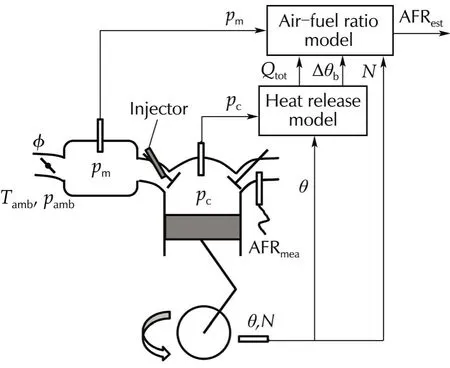
Fig.1 Air-fuel ratio(AFR)estimation model.p amb:ambient pressure,T amb:ambient temperature,p c:in-cylinder pressure,θ:crank angle,and φ:throttle angle.
The total heat release for the AFR model is obtained from the integration of the heat release rate from the start to the end of combustion[6].When crevice volumes and blow-by effects are omitted,the heat release rate can be computed from the relation

where Q is the gross heat release,γ is the ratio of specific heats,pcisthe in-cylinderpressure,V isthe cylinder volume,θis the crank angle,and Qhtis the heattransfer.The rapid burn angle is defined as the crank angle interval required for burning the bulk of the charge.In general,we consider that 10%to 90%of the mass fraction is burned.The different values of all inputs compared with their values at stoichiometric ratio are considered for the AFR calculation.The introduced AFR model can be obtained with the combination of the Taylor series expansion as follows:
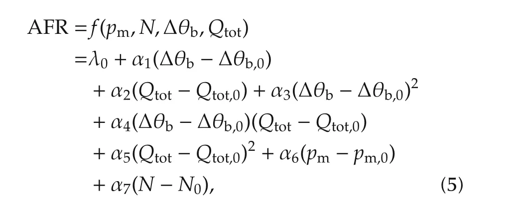
where λ0=f(pm,0,N0,Δθb,0,Qtot,0),and the subscript zero of each input,refer to the initial value at stoichiometric AFR.For the model inputs,pmis the intake manifold pressure(Pa),N is the engine speed(r·min−1),Qtotis the total heat release(kJ)and Δθbis the rapid burn angle(°).This equation utilises only linear terms of the intake manifold pressure and engine speed because their dynamic behaviours are slower than the combustion parametersobtained from in-cylinderpressure data.In the next section,the identification process for the AFR model is presented.
3 System identification
In this identification,considering a steady state AFR response,both the intake manifold pressure and the engine speed have a significant effect on the air mass flow rate.The fuel mass directly affects the total heat release and burn duration.The main AFR oscillation is caused by the total heat release and the rapid burn angle because the changing rate of the manifold pressure and the engine speed are slower compare to the variation of the combustion parameters.
The AFR values under various operating conditions are obtained from experiments by averaging over many working cycles.This is because the lambda sensors installed on the test bench have a certain delay and they cannot detect the value of AFR cycle-by-cycle.We consider both the variation of the throttle and the change of the fuel mass on the torque’s constant mode.The relation between the model inputs affected by the air mass flow rate and the AFR is shown in Fig.2(a).Moreover,the connection between the combustion parameters and the AFR is exhibited in Fig.2(b).
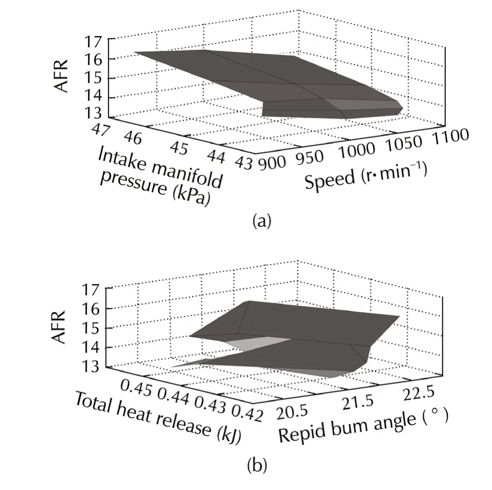
Fig.2 Relationship between inputs and the AFR.
The polynomial parameter estimation for this model is set up as follows:

The vector of regression is

Define the parameter vector as

Therefore,the output become

An estimate for y can now be calculated from n cycles of measurements using least squares regression.The output from the measurements defined by equation(9)are collected into an output vector,Y,and the regression vectors defined by equation(7),are collected into a regression matrix,Φ.

For the calculation of the estimated model parameters,we solve for the least squares estimateˆα

However,the ridge regression is applied to this problem for estimating the regression coefficients because the determinant of ΦTΦ is close to zero.The parameters of the AFR model can be calculated by using the following equation:

where k is the ridge parameter and I is the identity matrix.
4 Port injection AFR control of the SI engine using SAC
In this section,we introduce some behaviours of the port injection and the system model.Subsequently,the details of the controller design with the AFR model are presented.
4.1 Wall-wetting model for fuelling control
The wall-wetting phenomena have important effects on the fuel path of the AFR control system.The utilised mean value model in the control design accounts for the impingement and the evaporation process of the injected fuelon the walls[19].An empiricalmodel,defined in[20],has been utilised to express the port injection path dynamics.
In this work,the model can be considered as a firstorder system with unknown parameters.Moreover,the cooling loss and the variation of the combustion efficiency can be included as the unknown system disturbance.An adaptive controller that will be presented in the next section will control the plant with unknown parameters and reject the system disturbances.
4.2 Simple adaptive fuelling control
The simple adaptive control is applied to control the injected fuel of the port injection system.This controller uses the reference model for generating the desired signal.The control objective is to design the adaptive input making the AFR output,λest,fil(t),track the reference input,λd(t).The AFR control system using SAC,in associate with the AFR model,is shown in Fig.3.Note that,the first-order filter in this case is a low pass filter,with a transfer function 1/(τfils+1).The parameter τfildenotes the filter time constant.The measured AFR of the lambda sensor(λs)at the mixing points is only used for checking the performance of the AFR model.
We neglect the direct term of the wall-wetting model.In this way,the plant model is regarded as a minimum phase first-order system with a relative degree equal to one.Therefore,SAC can be applied for fuel injection control.The response of the controlled plant is required to follow the input-output behaviour of the first-order reference model in the form of

where am,bmand cmare model parameters.We select the first-order model to generate the desired trajectory for the AFR control system and define the tracking error as

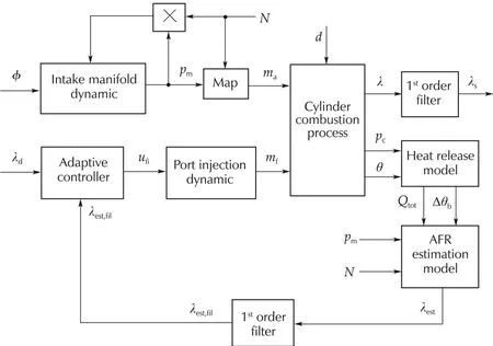
Fig.3 Block diagram of the AFR control system.
Using the values that can be measured,ey(t),xm(t),and um(t),the following total control signal is obtained.

where the adaptive gains,key,kxmand kumare obtained as the combination of proportional and integral gains.First,an adaptation law for key(t)is considered.

We then present the adaptation law for kxm(t)as

Finally,we design the adjustment law for kum(t)in accordance to

where γPand γIare parameters that affect the rate of adaptation.The σ terms following the idea of Ioannou and Tsakalis[21]in the equations are used here to avoid the divergence of the gains.The modified adaptive law with σ sacrifices the ideal stability properties in the disturbance-free case in order to achieve boundedness of all signals in the presence of disturbances.The adjustment of the controller gains corresponds to the system desired input,the model state variable,and the error between the plant and the reference model.The structure of SAC can be expressed as shown in Fig.4.
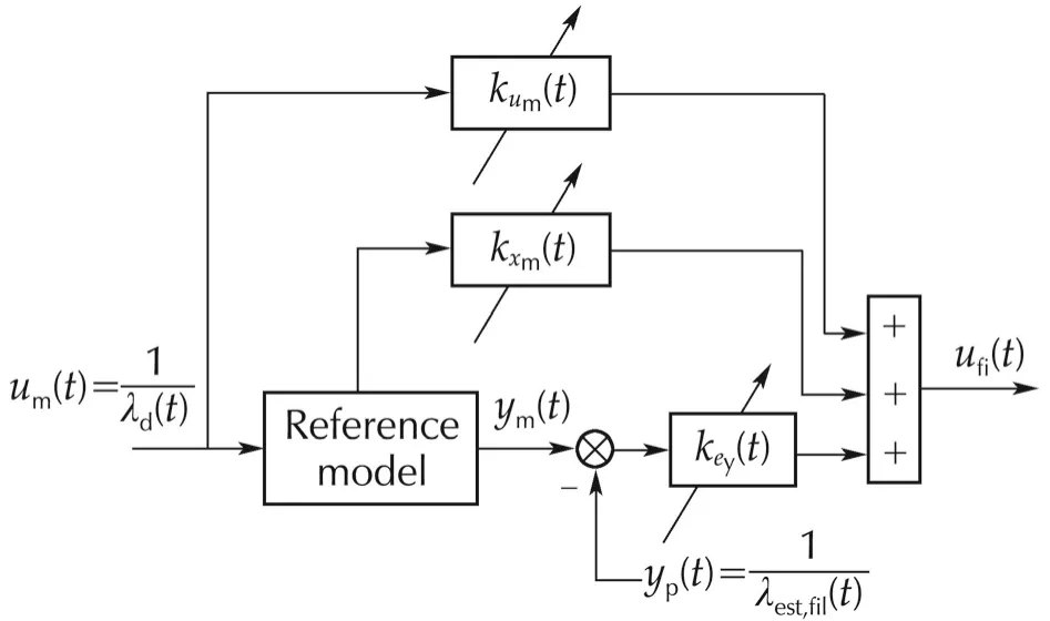
Fig.4 Schematic diagram of simple adaptive control(SAC).
SAC is suitable for AFR control applications because it can deal with the unknown parameters and the disturbances.There are some disturbances in this controlled system,such as,the variation of air mass flow rate,engine combustion efficiency and the residual burned gas.
5 Experimental results
The tests were performed on an engine test bench,which consisted of the six cylinders of the gasoline engine with a low inertia dynamometer.The air flow metre,in-cylinder pressure sensors,the intake manifold pressure sensor,UEGO sensors,and other components were installed on the engine system.The proposed AFR model and controller were implemented by a dSPACE rapid prototyping unit,which communicates with the real time interface(RTI)bypass system and the engine control unit(ECU).The engine test bench used for the AFR identification and control is shown in Fig.5.
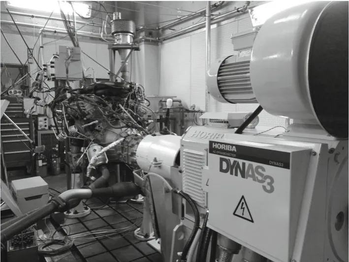
Fig.5 Engine test bench with dynamometer.
For system identification,the engine operated under the torque control mode,the variable valve timing(VVT)system was not activated,the spark advance(SA)was fixed,and the throttle was constant while the fuel injection mass was changed.There are three constant values of throttle angles in this identification scheme for a required data set.
5.1 AFR model validation
Two cases of the AFR model validation were performed,by changing the fuel-injected command during constant throttle and during the variation of the throttle under the fixed injected fuel.The AFR model parameters obtained from the system identification are shown in Table 1.
Fig.6 shows the experimentalresults forthe firstcase.The variation of the four model inputs(N,pm,Δθb,Qtot)caused by the amount of the injected fuel was presented.Additionally,the changing of the fuel injection command,the estimated AFR compared with the measured AFR from the sensor at the mixing point,and the error of the AFR calculation,are all shown.The model yielded effective results in the cases of various fuel injections during constant throttle and load torque values.The RMS of the AFR error was 0.53%and the maximum absolute error was 12.30%during the transient response.These errors were calculated and compared with the stoichiometric value.Both the estimated error and the variation of the calculated AFR values were less than the values obtained from the theoretical model presented in the literature review section.
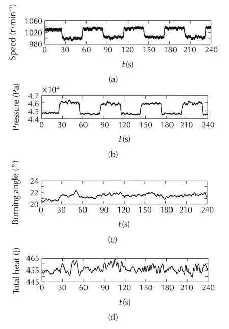
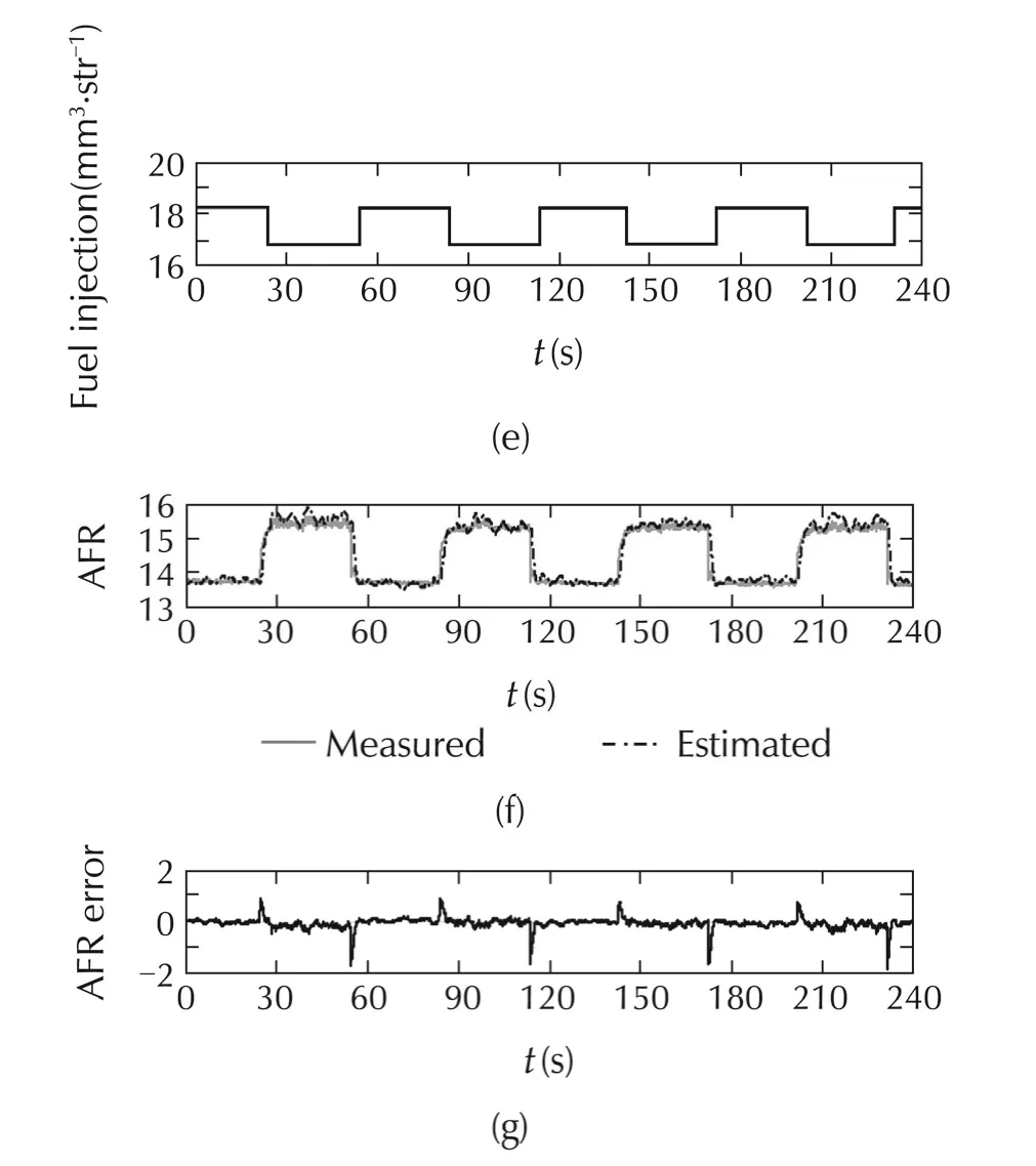
Fig.6 Experimental results for the AFR model validation while the throttle is constant.
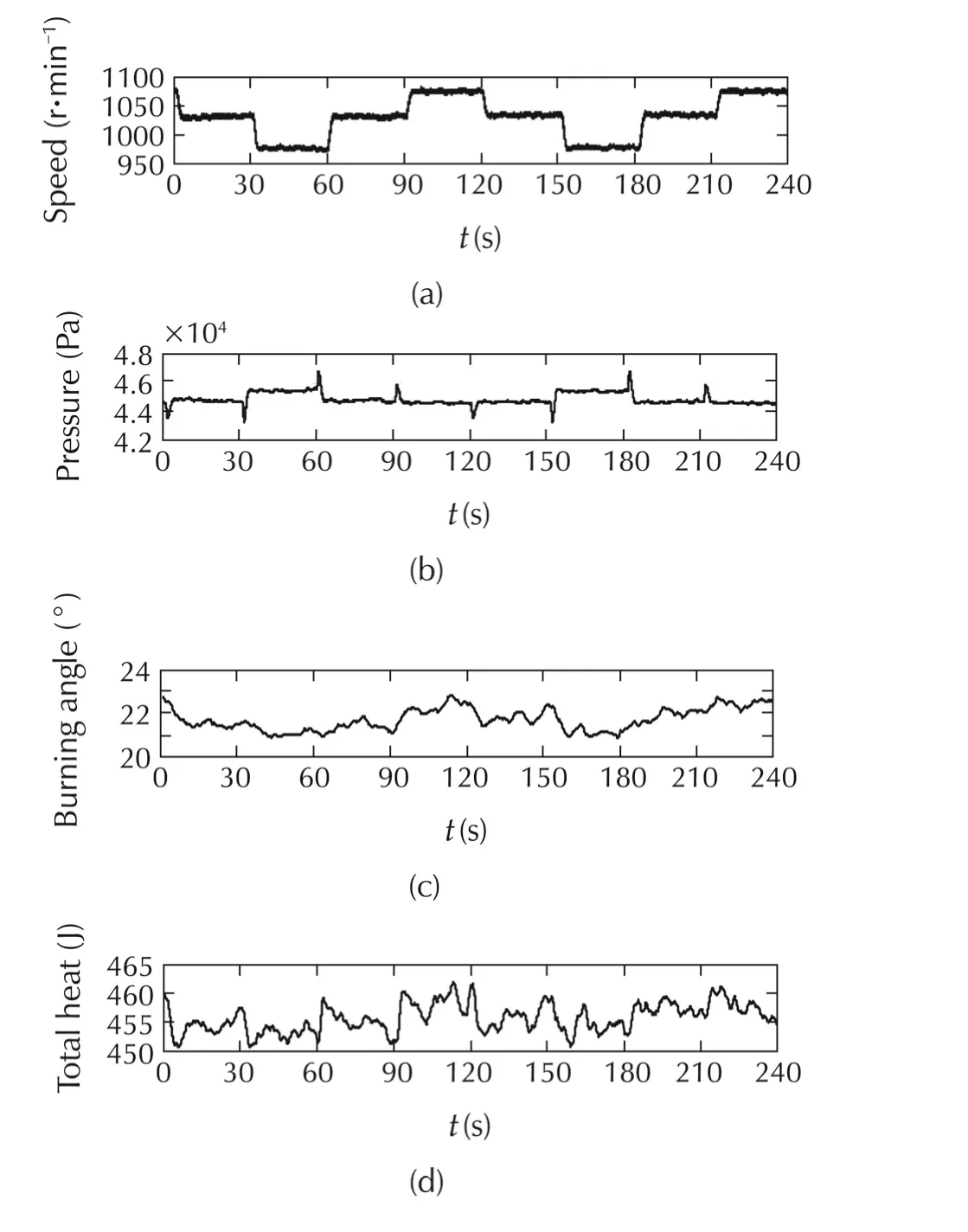
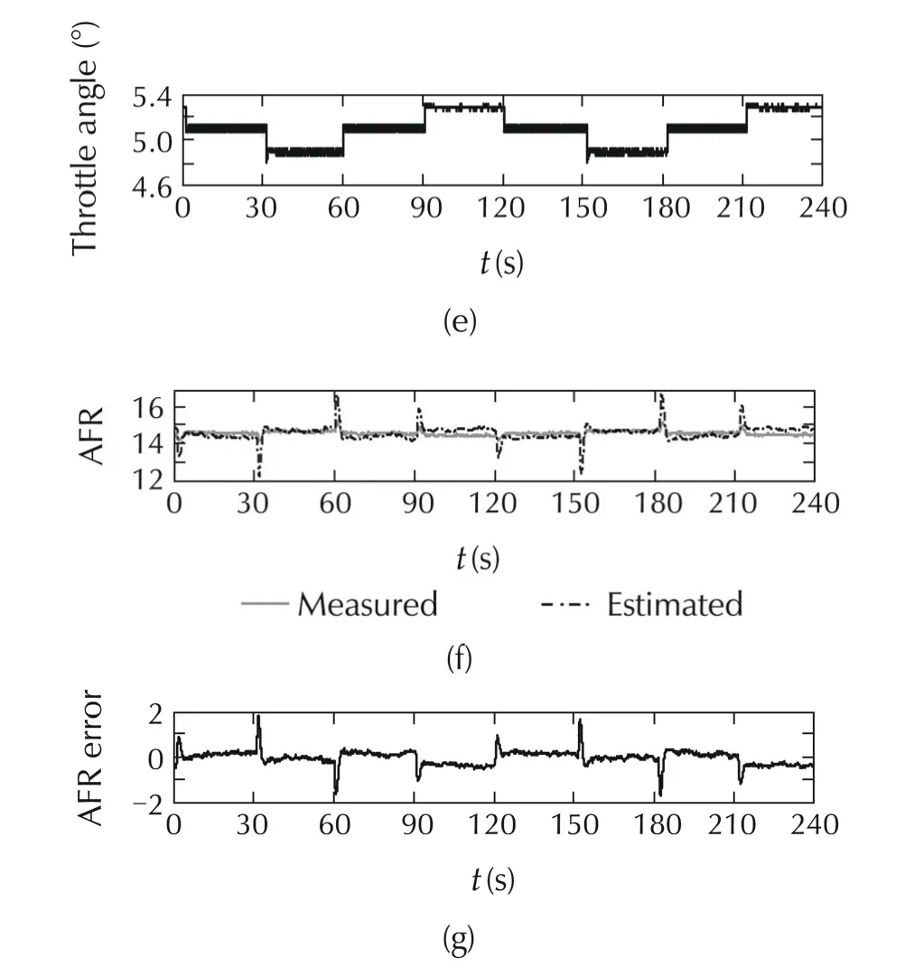
Fig.7 Experimental results for the AFR model validation with a constant rate of injected-fuel.
However,the response of this model exhibited some delay compared to the reaction obtained from the sensor.This delay was mainly owing to the model inputs calculated from the in-cylinder pressure data.The estimation of the AFR had a time delay of approximately 1.0 sbecause ofthe moving averaging processapplied to many working cyclesand the low-passfiltereffects.Subsequently,the effects of the throttle changing at a constant fuel injection were examined.Four model inputs,the throttle angle,and the AFR were exhibited in Fig.7.The calculated AFR yielded some error,especially during the transient period.The RMS of the AFR error was 0.03%and the maximum absolute error was 12.88%.This error results from the static system identification.In the torque control mode,the shift of the throttle angle yielded the main effect on the engine speed changes,while small changes in the AFR were observed during steady state.The time delay value in this case was almost the same as in the previous case.
5.2 AFR control
The SAC control performance,tracking error,controlled fuel injection,adaptation gains,and AFR estimation efficiency,are shown in Fig.8.In this case,the controller parameters are γP=1000, γI=500,and σ=0.001.Furthermore,the output of the AFR model is utilised as a controller feedback signal.Additionally,the model response as a result of changes in the controller parameters was investigated.The results are shown in Fig.9.In this figure,the controller parameters are as follows:(a) γP=800,γI=300,and σ =0.001,(b)γP=900,γI=400,and σ =0.001,(c) γP=1100,γI=600,and σ =0.001,and(d)γP=1200,γI=700,and σ=0.001.
The sampling time in the experimental calculation program was 0.25 ms,which was improper for the controller application.Therefore,a suitable trigger signal for the AFR controller was designed.This trigger signal generated the command output signal that can activate the port’s fuel injection system,which also included the time delay.
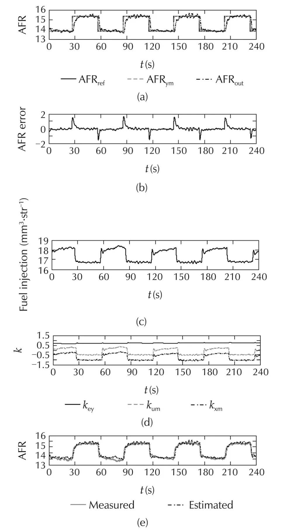
Fig.8 Experimental results for SAC control performance.
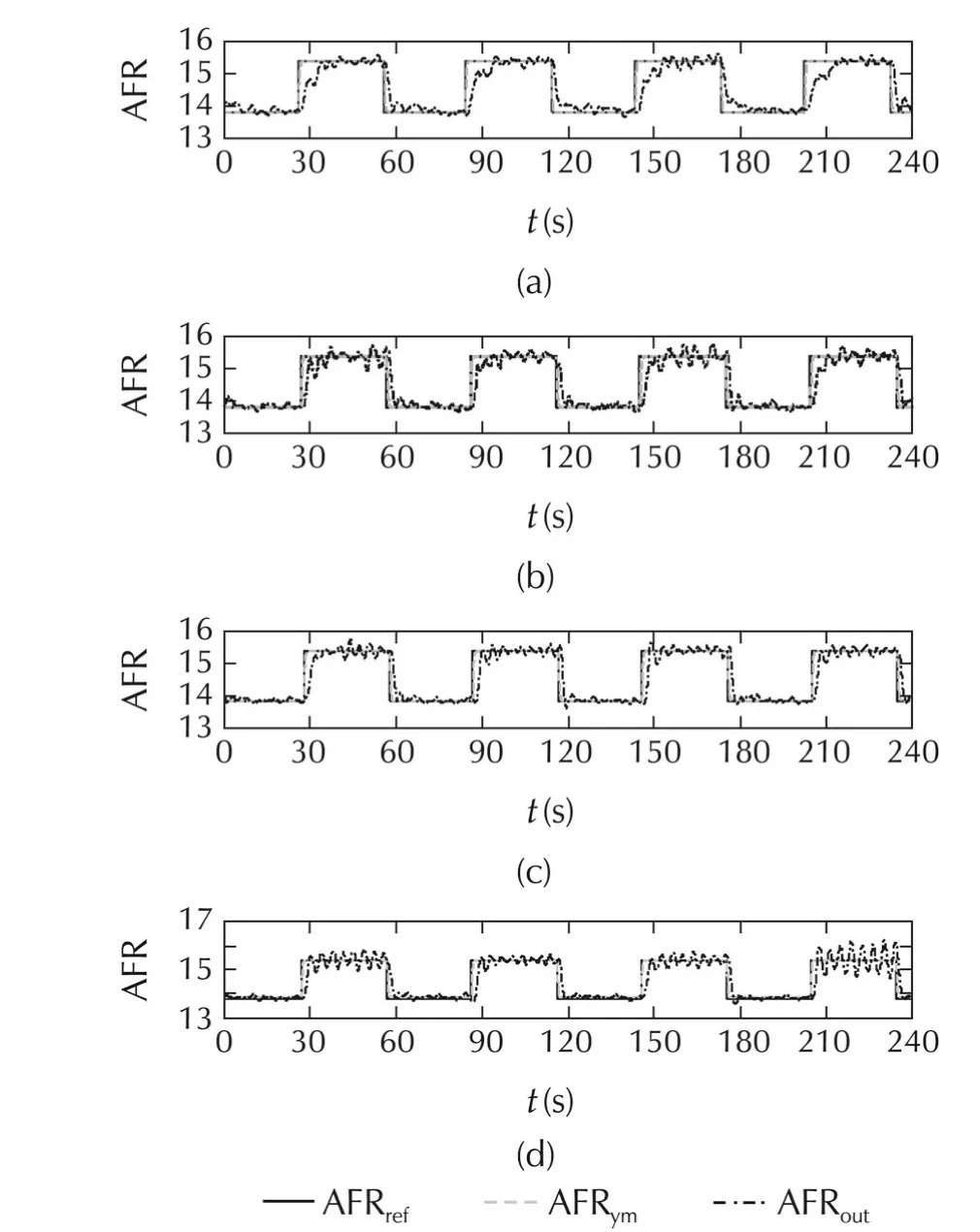
Fig.9 Effects of changing controller parameters.
In regard to the safety conditions,the injected fuel output was limited to a specified fuel mass flow rate entering the combustion chamber.The AFR calculation delay was also another important factor that affected the performance of the SAC.In this experiment,all inputs of the AFR modelcontain a time delay,especially the inputs obtained from the combustion parameters.This was because ofthe variation ofthe in-cylinderpressure,and the use of the moving average operator and the filter.These delays had affected the feedback signal used by SAC.Because of these reasons,the transient response of the SAC was quite slow.Therefore,this AFR model was not suitable for transient control applications.Additionally,the performance of the SAC was seriously affected by the AFR estimation error.
Stability analysis of the controlled system can be considered based on some assumptions.First,we omitted the dynamics of the intake manifold and the crank shaft.The time delay of the feedback was then neglected.Finally,we also ignored the direct term of the plant transfer function.Therefore,in ideal cases,we can prove the stability of the entire system using the idea presented in[17].In practical applications,and however,all these effects should be considered.We envisage pursuing this as future work.
6 Conclusions
Based on the experimental results of this study,we can conclude that the proposed model shows effectiveness in calculating the AFR of the SI engine using information from the in-cylinder pressure.In addition,the SAC with the cylinderpressure-based lambda sensor can be applied to control the AFR of the port injection gasoline engine.However,the AFR model response elicits a delay because of the use of the cylinder pressure data.It also elicits some important effects in AFR control applications,especially during the transient period.Therefore,the improvements of the AFR calculation performance should be considered and pursued as future work.
Acknowledgements
We would like to thank Dr.Jinwu Gao for providing us with suggestions on the calculation of combustion parameters.
[1]P.Tunestal.The Use of Cylinder Pressure for Estimation of the Incylinder Air/Fuel Ratio of An Internal Combustion Engine.Ph.D.Thesis.Berkeley:University of California,2000.
[2] P.Wibberley,C.Clark.An Investigation of Cylinder Pressure as Feedback for Control of Internal Combustion Engines.SAE Technical Paper 890396.1989:DOI 10.4271/890396.
[3]G.W.Pestana.Engine Control Methods Using Combustion Pressure Feedback.SAE Technical Paper 890758.1989:DOI:10.4271/890758.
[4]P.Li,T.Shen,J.Kako,et al.Cyclic moving average control approach to cylinder pressure and its experimental validation.Journal of Control Theory and Applications,2009,7(4):345–351.
[5]J.Yang,T.Shen,X.Jiao.Air-fuel ratio control with stochastic L2disturbance attenuation in gasoline engines.Journal of Control Theory and Applications,2013,11(4):586–591.
[6]J.B.Heywood.Internal Combustion Engine Fundamentals.New York:McGraw-Hill,1988.
[7]R.Cremers.Beginning for Cylinder Pressure Based Control.Report No.WVT.Eindhoven:Eindhoven University ofTechnology,2007.
[8] A.T.Lee,M.Wilcutts,P.Tunestal,et al.A method of lean airfuel ratio control using combustion pressure measurement.JSAE Review,2001,22(4):389–393.
[9] P.Tunestal,J.K.Hedrick.Cylinder air/fuel ratio estimation using net heat release data.Control Engineering Practice:Advances in Automotive Control,2003,11(3):311–318.
[10]J.S.R.Jang,C.T.Sun,E.Mizutani.Neuro-fuzzy and Soft Computing:A Computational Approach to Learning and Machine Intelligence.Englewood Cliffs:Prentice Hall,1997.
[11]J.C.Gilkey,J.D.Powell.Fuel-air ratio determination from cylinder pressure time histories.Journal of Dynamic Systems Measurement and Control–Transactions of the ASME,1985,107(4):252–257.
[12]R.S.Patrick.Air-fuelRatio Estimation in An Otto Cycle Engine:Two Methods and Their Performance.Ph.D.Thesis.Stanford:Stanford University,1989.
[13]W.E.Leisenring,S.Yurkovich.Comparative analysis of closed loop AFR control during cold start.Proceedings of the American Control Conference,Philadelphia:IEEE,1998:1377–1382.
[14]Y.Yildiz,A.Annaswamy,D.Yanakiev,et al.Adaptive air fuel ratio control for internal combustion engines.Proceedings of the American Control Conference,Seattle:IEEE,2008:2058–2063.
[15]K.J.Astrom,B.Wittenmark.Adaptive Control.Reading,MA:Addison-Wesley,1995.
[16]I.Bar-Kana,H.Kaufman.Simplified adaptive control of uncertain systems.International Journal of Adaptive Control System and Signal Processing,1988,2(2):133–143.
[17]I.Bar-Kana.Simple adaptive control–a stable direct model reference adaptive control methodology.International Journal of Adaptive Control and Signal Processing,2014,28(7/8):567–603.
[18]P.Tunestal.Estimation of the In-Cylinder Air/Fuel Ratio of An Internal Combustion Engine by the Use of Pressure Sensors.Ph.D.Thesis.Sweden:Lund Institute of Technology,2001.
[19]X.Jiao,J.Zhang,T.Shen,et al.Adaptive air-fuel ratio control scheme and its experimental validation for port-injected spark ignition engines.International Journal of Adaptive Control and Signal processing,2015,29(1):41–63.
[20]J.S.Souder,J.K.Hedrick.Adaptive sliding mode control of airfuel ratio in internal combustion engines.International Journal of Robust and Nonlinear Control,2004,14(6):525–541.
[21]P.A.Ioannou,K.S.Tsakalis.A robust direct adaptive control.IEEE Transaction on Automatic Control,1986,31(11):1033–1043.

his B.E.(2005),and M.E.(2008)degrees in Mechanical Engineering from Suranaree University of Technology,Thailand,and M.Sc.(2012)in Systems Engineering and Science from Shibaura Institute of Technology,Japan.He is currently a Ph.D.candidate at the Shibaura Institute of Technology.His main interests include the SI engine control,system modelling,and adaptive control.E-mail:nb13504@shibaurait.ac.jp.

Kazuhisa ITOreceived his B.E.(1993),M.E.(1995),and Ph.D.(2001)degrees in Mechanical Engineering from Sophia University.He is a full professor at the Department of Machinery and Control Systems,Shibaura Institute of Technology.His currentresearch interests include controllerdesign for nonlinear systems and its application to mechanical systems and agricultural engineering.E-mail:kazu-ito@shibaura-it.ac.jp.
†Corresponding author.
E-mail:nb13504@shibaura-it.ac.jp.Tel.:+81-48-687-5176;fax:+81-48-687-5197.
This work was supported by the Toyota Motor Corporation.
©2015 South China University of Technology,Academy of Mathematics and Systems Science,CAS,and Springer-Verlag Berlin Heidelberg
杂志排行
Control Theory and Technology的其它文章
- Distributed dynamic pricing based on demand-supply balance and voltage phase difference in power grid
- Decentralized load frequency control for two-area interconnected power system
- Increasing the operating area of shunt active filters by advanced nonlinear control
- Estimation and feedback control of air-fuel ratio for gasoline engines
- Gain-scheduling control of a floating offshore wind turbine above rated wind speed
- New adaptive vector control methods for induction motors with simpler structure and better performance
