Identification of integrating and critically damped systems with time delay
2015-12-05BAJARANGBALISomanathMAJHI
BAJARANGBALI,Somanath MAJHI
Department of Electronics and Electrical Engineering,Indian Institute of Technology Guwahati,Guwahati-781039,India
Received 12 February 2014;revised 1 January 2015;accepted 1 January 2015
Identification of integrating and critically damped systems with time delay
BAJARANGBALI†,Somanath MAJHI
Department of Electronics and Electrical Engineering,Indian Institute of Technology Guwahati,Guwahati-781039,India
Received 12 February 2014;revised 1 January 2015;accepted 1 January 2015
This paper presents identification of second order plus dead time(SOPDT)integrating and critically damped systems based on relay feedback testing.Relay with hysteresis is applied to the unknown system to get the sustained oscillations also called as limit cycle.The limit cycle parameters are utilized in mathematical expressions which are derived using state space technique so that exact process model parameters are estimated.As the relay with hysteresis helps in generating sustained oscillations and also reduces effect of measurement noise which is an important issue in system identification.Different types of processes in the form of transfer function models are considered to show the efficacy of the proposed method and results are compared with available methods in the literature with and without noise effect.
System identification,time delay systems,relay with hysteresis
DOI 10.1007/s11768-015-4018-5
1 Introduction
System identification is mathematical modeling of an unknown system orprocess in terms oftransferfunction form,utilizing the measurements of system’s input and output signals.Recently Liu et al.[1]presented a review on various methods of process dynamics identification.Åstr¨om and Eykhoff[2]had given a detailed survey on system identification and also mentioned the importance of identification for designing a control strategy.Identification can be done by step or pulse testing in open-loop or closed-loop mode[3].However,openloop step testing can not be applied for systems with large time constants having load disturbances,whereas closed-loop step testing takes less time compared to open-loop test.Åstr¨om and H¨agglund[4]introduced relay feedback testing called autotune variation(ATV)method for estimation of unknown process model parameters with the help of describing function approximation(DFA)technique.This ATV method identifies process information around the important frequency called the ultimate frequency.Hang etal.[5]presented a tutorial review for auto-tuning of process controllers using relay feedback technique.In DFA technique relay isapproximated by a gain,hence the estimated parameters were approximate.A number of relay based identification methods are proposed to obtain process models in terms of transfer functions.Li et al.[6]suggested estimation of unknown process model parameters for stable and unstable processes employing two relay tests.Shen et al.[7]considered dual input describing function approach(DIDF)and an input biased relay feedback experiment to identify two points on the Nyquist curve.However,this method can be applied only for stable systems.Padhy and Majhi[8]presented algorithms for identification of stable and unstable first order systems using DFA method and an ideal relay.Since the model parameters estimated by DFA technique are approximate hence,many authors explored research towards exact analysis so that more accurate parameters are estimated.Wang et al.[9]derived analytical expressions for amplitudes and frequency of the limit cycle under relay feedback for a first order plus dead time(FOPDT)systems.Jahanmiri and Fallahi[10]developed algorithms for identification of second order processes based on the open loop test and step input variable.Majhi and Atherton[11]and Majhi[12,13]suggested exact analysis for general model structure employing state space approach.Vivek and Chidambaram[14]proposed improved identification algorithms utilizing Laplace transform method and single symmetric relay feedback test.Thyagarajan and Yu[15]developed shape factor of relay feedback responses to estimate the unknown process model parameters.Liu and Gao[16]applied Newton-Raphson iteration method for obtaining exact expressions for integrating and unstable processes.Panda et al.[17]identified dynamics of integrating and time delay processes with the help of single relay feedback test.In the literature many authors presented various identification algorithms employing different types of relays.In this paper we are proposing the application of relay with hysteresis since it has got the advantage of generating the limit cycle and reducing the measurement noise effect[4].Bajarangbali et al.[18]have proposed identification of second order overdamped,underdamped and FOPDT process dynamics without considering integrating and critically damped systems.It is advantageous to generalize a SOPDT system in different types of systems hence,the mathematical expressions presented in[18]are extended in this paper to derive the expressions for SOPDT integrating and critically damped systems.This paper is arranged in the following Sections,proposed method is given in Section 2,mathematical expressions are derived in Section 3,results and discussions are detailed in Section 4 and finally conclusions are presented in Section 5.
2 Proposed method
The block diagram shown in Fig.1 mainly consists of relay with hysteresis,unknown system to be modeled and a denoising block.The relay is connected as an input to the system or process to generate sustained oscillations containing process information in the form of parameters like amplitude and time period.In real time scenarios normally the process output is corrupted with measurement noise so to remove the maximum noise content,a denoising block[18]is used.This denoising block as shown in Fig.2 consists of a derivative block(s1)connected to the closed loop block of an integrator(1/s)and one more derivative block(s2).Initially,the noisy limit cycle output¯y(t)is passed through the first derivative block which gives the first derivative output in terms of the rate of change of the noisy limit cycle with respect to time.This output is passed through closed loop sequence of an integrator and the second derivative block.The integrator helps in removing the higher order harmonics present at the derivative(s1)output,assuming zero initial conditions ands2is used further to improve the results.Hence,a noise free limit cycle outputy(t)is obtained.The limit cycle parameters are utilized in the analytical expressions which are derived based on state space method to estimate the unknown process model parameters of integrating and critically damped systems.The noisy and denoised limit cycles are as shown in Fig.3.
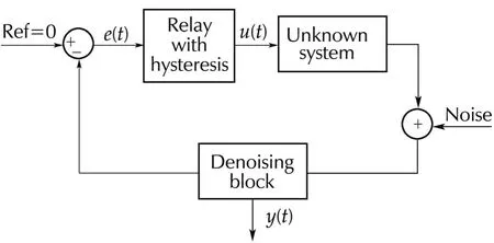
Fig.1 Relay feedback block diagram.
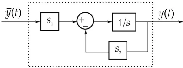
Fig.2 Denoising block.
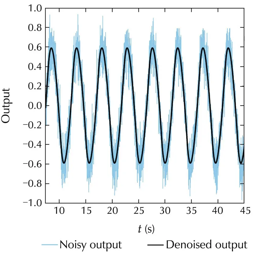
Fig.3 Noisy and denoised outputs.
For convenience the procedure to implement the proposed method is explained below.In Fig.1 the relay can be implemented with the help of op-amps or FPAA(field programmable analog array)[18,19]by appropriately selecting the relay amplitude,sampling time and hysteresis values in the range of volts,milliseconds and millivolts,respectively.These relay parameters can be varied accordingly to control the amplitude of limit cycle output.The relay is connected in the feedback to obtain sustained oscillations at the output.The denoising block consisting of derivative blocks and an integrator can be implemented using a set of op-amps or FPAA.Hence,a noise free limit cycle and the relay output can be observed on oscilloscope connected at the system output and relay output terminals,respectively.The limit cycle and other parameters can be measured by making simple observation.Utilizing these quantities in the corresponding analytical expressions derived,the process model parameters can be estimated.
3 Derivation of mathematical expressions
In this section,the SOPDT overdamped and underdamped expressions[18]are extended to develop the analytical expressions for estimation of accurate parameters of integrating and critically damped process models.Therefore,rewriting the stable SOPDT system as

whereaandbare the process model parameters,Kthe steady state gain,θ the process time delay andcis a constant.The system in equation(1)becomes an overdamped with the conditionb2gt;4acand underdamped forb2lt;4ac.For convenience the expressions for overdamped and underdamped systems from[18]are derived here.Let us consider equation(1)in the following form:
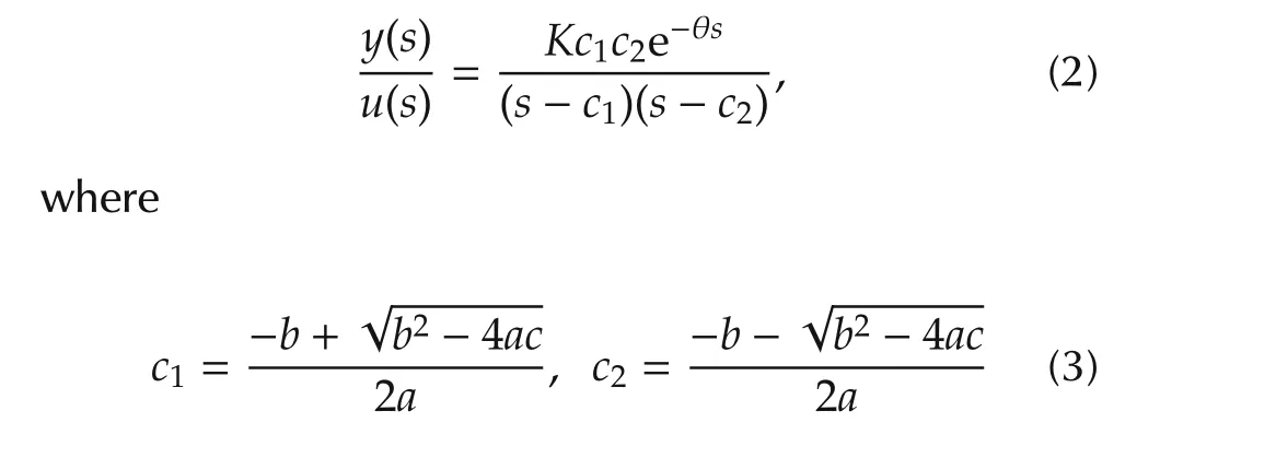
for overdamped system.Transforming equation(2)to the following state space equations:
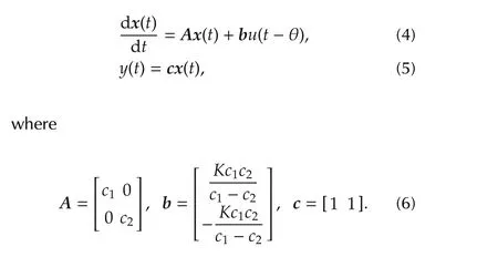
The delayed relay output provides two piecewise constant input signals(for time rangest0tt1andt1tT+t0)to the process for half limit cycle output.Hence,the solution of equation(4)with reference to delayed relay output for time ranget0tt1,can be written as

similarly,fort1tT+t0,the solution becomes

whereTis half time period of limit cycle output,hthe relay amplitude,t0the time instant at hysteresis value at which point actual relay switching takes place andt1the time where the second derivative output of limit cycle shows abrupt change as shown in Fig.4 and the process time delay(θ)is also given by θ =t1−t0[13].
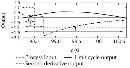
Fig.4 Limit cycle and it’s second derivative output.
Substitutingt=t1in equation(7)we obtain

whereIis an identity matrix of the order ofA.Symmetrical limit cycle leads tox(T+t0)=−x(t0).Hence,using equations(8)and(9)the following expression for initial condition is obtained:


Substituting forcandx(t0)in above equation and solved to get

Expression for peak amplitude is obtained from the following equation:

which is further solved to


which is reduced to

The above equation is solved with substitution ofc,Aandx(ˆt)to obtain

Hence,equations(12),(14)and(17)are modified to obtain the following expressions:
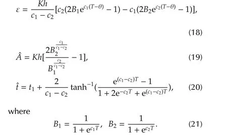
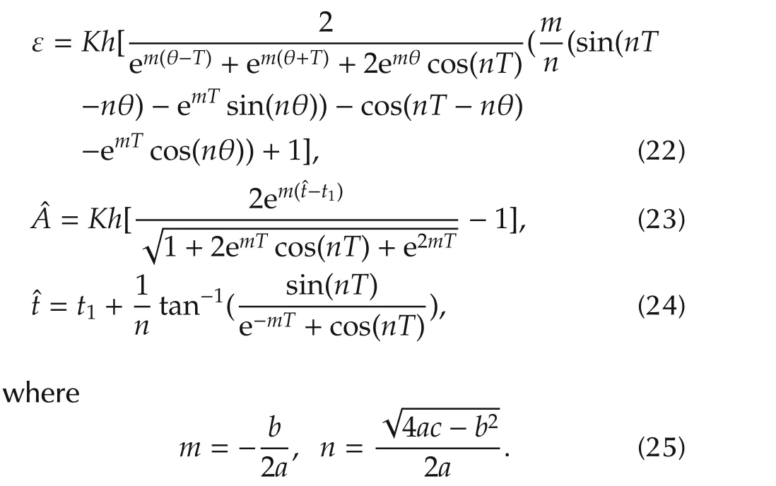
Similarly,for underdamped systems substitutingc1=m+jnandc2=m−jnin equations(12),(14)and(17)and solved to obtain the following expressions,respectively.
3.1 Expressions for integrating systems
Substitutinga=T1,b=1 andc=0 in equation(1),the following transfer function for SOPDT integrating system is obtained:

whereT1is the time constant.Hence,with reference to equation(26)makinga=T1,b=1 andc=0 in equation(3)we can writec1→0 andc2=−1/T1,which are used in equations(18)–(20)to obtain expressions for integrating systems.Expression(20)can be modified as

The expression for ε is obtained by substitutingB1andB2in equation(18)as

Solving(29)we obtain the following equations:
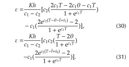
Further simplification leads to

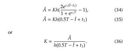
Now,to obtain the expression for peak amplitudeˆA,equation(28)is substituted in equation(19)to get

Again substituting forB1,c1and solving further the following expressions are obtained:
B1andB2are substituted in equation(27)to get the expression in terms ofˆtas

Since,c1→0 above equation reduces to

which is further simplified to

The expressions for ε andˆtin terms ofT1are rewritten as

Hence,substituting the parameters of relay and limit cycle in expression(36),Kis estimated similarly,other parametersT1and θ are obtained from simultaneous solution of equations(41)and(42).
3.2 Expressions for critically damped systems
The following transfer function for SOPDT critically damped system is obtained by substitutinga=T12,b=2T1andc=1 in equation(1)which is considered as an underdamped system in this section.

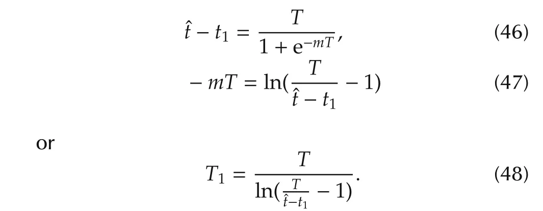
with reference to the above transfer functionmandnin equation(25)can be written as asm=−1/T1andn→0.Hence,substitutingn→0 in equations(22)to(24)we obtain expressions in terms ofK,T1and θ as follows.
Equation(24)can be reduced to

which is again modified as

Using L’Hˆospital’s rule above equation is further simplified to obtain the following expressions
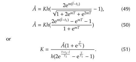
Now,equation(23)is solved to get
Similarly,the expression for ε is obtained from equation(22)as

The above equation can be represented in terms ofT1as

Hence,the unknown parametersT1andKare estimated from explicitexpressions(48)and(51),respectively similarlyθis obtained from equation(53)using matlab function fzero.
4 Results and discussions
In this section,well known examples are considered and results are compared with recent methods available in the literature.Relay parameters and measured limit cycle parameters are substituted in the corresponding expressions derived to estimate the unknown process model parameters with and without noise effect.As mentioned earlier,effect of measurement noise is reduced using relay with hysteresis and denoising block.Hysteresis width is considered to be twice the standard deviation ofnoise.Results are compared using Nyquist’s plot and performance is evaluated by calculating estimation error(Eerror)between actual process and identified process model using integral of absolute error(IAE)criterion.

wherepis the phase crossover frequency of the actual process,Gpm(jω)is the identified process model andG(jω)is the actual process.The proposed models 1 and 2 identified in the absence of measurement noise and with noise,respectively are given in tabular form for all examples.

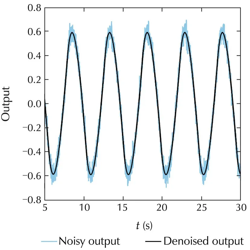
Fig.5 Noisy and denoised limit cycles.
Using the relay and denoised limit cycle parameters in the corresponding expressions the process model is identified.The proposed models 1 and 2 in the absence of measurement noise and with noise,respectively and the model proposed by Panda et al.[17]without noise effect,are given in Table 1 with corresponding estimation error.From Table 1,it can be observed that the proposed method can be successfully used to identify the process models even under noisy environment.
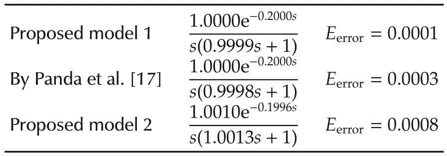
Table 1 Transfer function models for Example 1.


Table 2 Transfer function models for Example 2.
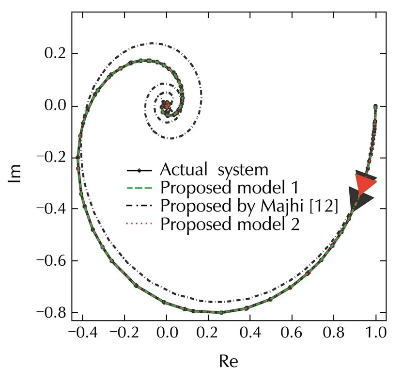
Fig.6 Nyquist’s plots.
From Nyquist’s plots it can be seen that the identified models are closely following the actual system.
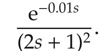
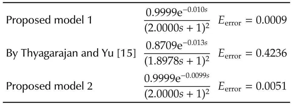
Table 3 Transfer function models for Example 3.
5 Conclusions
Relay with hysteresis is used to extract the process information in the form of limit cycle parameters.State space based mathematical expressions are derived to estimate the unknown process model parameters of integrating and critically damped systems.Effect of measurement noise is mitigated using relay with hysteresis and denoising block.Transfer function models from well known processes are considered to show the general usefulness of the proposed method.Results are compared using IAE based estimation error values and Nyquist’s plots.
Acknowledgements
I am highly grateful to PES Institute of Technology,Bangalore South Campus,Karnataka,India for deputing me to study at Indian Institute of Technology Guwahati(IITG),a prestigious institute in India and providing me with financial assistance.I sincerely thank Dr.J.Suryaprasad,Director,PESIT South Campus,Bangalore for his help and support.
[1]T.Liu,Q.G.Wang,H.P.Huang.A tutorial review on process identification from step or relay feedback test.Journal of Process Control,2013,23(10):1597–1623.
[2]K.J.Åstr¨om,P.Eykhoff.System identification-A survey.Automatica,1971,7(2):123–162.
[3]C.C.Yu.Introduction.Autotuning of PID controllers-A relay feedback approach.London:Springer-Verlag,2nd Edition,1999:1–8.
[4]K.J.Åstr¨om,T.H¨agglund.Automatic tuning of simple regulators with specifications on phase and amplitude margins.Automatica,1984,20(5):645–651.
[5]C.C.Hang,K.J.Åstr¨om,Q.G.Wang.Relay feedback autotuning of process controllers a-tutorial review.Journal of Process Control,2002,12(1):143–162.
[6]W.Li,E.Eskinat,W.L.Luyben.An improved auto tune identification method.Industrial and Engineering Chemistry Research,1991,30(7):1530–1541.
[7]S.H.Shen,J.H.Wu,C.C.Yu.Use of biased-relay feedback for system identification.AIChE,1996,42(4):1174–1180.
[8]P.K.Padhy,S.Majhi.Relay based PI-PD design for stable and unstable FOPDT processes.Computers and Chemical Engineering,2006,30(5):790–796.
[9]Q.G.Wang,C.C.Hang,B.Zou.Low order modeling from relay feedback systems.Industrial and Engineering Chemistry Research,1997,36(2):375–381.
[10]A.Jahanmiri,H.R.Fallahi.New methodsforprocess identification and design of feedback controller.Trans IChemE,1997,75(5):519–522.
[11]S.Majhi,D.P.Atherton.Autotuning and controller design for processes with small time delays.IEE Proceedings on Control Theory and Applications,1999,146(5):415–424.
[12]S.Majhi.On-line PI control of stable processes.Journal of Process Control,2005,15(8):859–867.
[13]S.Majhi.Relay based identification of processes with time delay.Journal of Process Control,2007,17(2):93–101.
[14]S.Vivek,M.Chidambaram.Identification using single symmetrical relay feedback test.Computers and Chemical Engineering,2005,29(7):1625–1630.
[15]T.Thyagarajan,C.C.Yu.Improved auto tuning using shape factor from relay feedback.Industrial and Engineering Chemistry Research,2003,42(20):4425–4440.
[16]T.Liu,F.Gao.Identification of integrating and unstable processes from relay feedback.Computers and ChemicalEngineering,2008,32(12):3038–3056.
[17]R.C.Panda,V.Vijayan,V.Sujatha,et al.Parameter estimation of integrating and time delay processes using single relay feedback test.ISA Transactions,2011,50(4):529–537.
[18]Bajarangbali,S.Majhi,S.Pandey.Identification of FOPDT and SOPDT process dynamics using closed loop test.ISA Transactions,2014,53(4):1223–1231.
[19]S.Majhi,V.Kotwal,U.Mehta.FPAA-based PI controller for DC servo position control system.IFAC Conference on Advances in PID Control,Brescia Italy,2012:1–5.
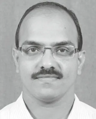
BAJARANGBALIis a Ph.D.candidate at Indian Institute of Technology Guwahati,India.He obtained his B.E.in Instrumentation Technology from Mysore University,India,and M.Tech.in Computer Applications in Industrial Drives from Visvesvaraya Technological University,India.He has eight years teaching experience at PESIT-BSC,Bengaluru,India.His research interests are relay based process identification and controller design.E-mail:bajarangbali@iitg.ernet.in.
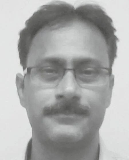
Somanath MAJHIis currently a professor in the Department of Electronics and Communication Engineering at Indian Institute of Technology,Guwahati.He received his Ph.D.from Sussex University,England,and he has been awarded the Commonwealth Scholarship and the Alexander von Humboldt Research Fellowship for his doctoral and postdoctoral research programmes.He is a life member of Systems Society of India and Indian Society for Technical Engineers.He has to his credited more than 125 research papers in reputed national and international journals and conferences.His research interests include relay control systems,design of automatic controllers,model identification,and application of control theory to communication systems.E-mail:smajhi@iitg.ernet.in.
†Corresponding author.
E-mail:bajarangbali@iitg.ernet.in.Tel.:+91-8011012736;fax:+91-361-2582542.
©2015 South China University of Technology,Academy of Mathematics and Systems Science,CAS,and Springer-Verlag Berlin Heidelberg
杂志排行
Control Theory and Technology的其它文章
- Variable selection in identification of a high dimensional nonlinear non-parametric system
- Model predictive control for hybrid vehicle ecological driving using traffic signal and road slope information
- Immersion and invariance adaptive control of a class of continuous stirred tank reactors
- Pinning synchronization of networked multi-agent systems:spectral analysis
- Discrete-time dynamic graphical games:model-free reinforcement learning solution
- Topology-preserving flocking of nonlinear agents using optimistic planning
