Model predictive control for hybrid vehicle ecological driving using traffic signal and road slope information
2015-12-05KaijiangYUJunqiYANGDaisukeYAMAGUCHI
Kaijiang YU ,Junqi YANG ,Daisuke YAMAGUCHI
1.School of Electrical Engineering and Automation,Henan Polytechnic University,Jiaozuo Henan 454000,China;
2.School of Information Science and Electrical Engineering,Kyushu University,Fukuoka Fukuoka 8190395,Japan
Received 4 May 2014;revised 3 January 2015;accepted 3 January 2015
Model predictive control for hybrid vehicle ecological driving using traffic signal and road slope information
Kaijiang YU1†,Junqi YANG1,Daisuke YAMAGUCHI2
1.School of Electrical Engineering and Automation,Henan Polytechnic University,Jiaozuo Henan 454000,China;
2.School of Information Science and Electrical Engineering,Kyushu University,Fukuoka Fukuoka 8190395,Japan
Received 4 May 2014;revised 3 January 2015;accepted 3 January 2015
This paper presents development of a control system for ecological driving of a hybrid vehicle.Prediction using traffic signal and road slope information is considered to improve the fuel economy.It is assumed that the automobile receives traffic signal information from intelligent transportation systems(ITS).Model predictive control is used to calculate optimal vehicle control inputs using traffic signal and road slope information.The performance of the proposed method was analyzed through computer simulation results.Both the fuel economy and the driving profile are optimized using the proposed approach.It was observed that fuel economy was improved compared with driving of a typical human driving model.
Ecological driving,model predictive control,intelligent transportation systems,traffic signal,optimal control
DOI 10.1007/s11768-015-4058-x
1 Introduction
Nowadays,many researchers have studied CO2emission reduction and improvement of mileage for vehicles to save global environment[1,2].For example,there are advancements of heat efficiency of engines,introduction of idling stop systems,developments of hybrid cars which have both the engine and the motor(in this paper,the engine represents the internal combustion engine,and the motor represents the electric motor),and so on.Further,ecologicaldriving(eco-driving)is one of effective approaches for improvement of fuel economy for vehicles.Typical eco-driving techniques require moderate accelerator or brake pedal manipulations,low accelerations and decelerations,and so on.However,there are many considerable things which should be taken into account on the roads for performing ecodriving:the shape of the roads,traffic signal switching,the motion of surrounding vehicles and so on.For performing eco-driving easily,many researchers have been studied driver assistance systems.Intelligent transportation systems(ITS)enables road-to-vehicle and vehicleto-vehicle communication owing to the development of communication technologies.Eco-driving is provided if the vehicle can perceive information of coming environment using ITS.For example,a road grade is considered for eco-driving assist systems[1–3].The fuel economy was improved 4.5%by using information of the road grade in advance to assist ecological driving compared with a conventional adaptive cruise control(ACC)system[2].Both dynamic programming and the equivalent consumption minimization strategy were utilized to optimize the battery state of charge(SOC)profile with terrain information for a hybrid vehicle power management problem in[4].Research on performance of an eco-driving nonlinear model predictive control(MPC)system for a power-split HEV during car following was accomplished in[5].In[6]and[7],a model predictive control algorithm with a simplified model for a powersplit HEV was proposed to optimize the fuel economy.The phase of the traffic signal and the motion of surrounding vehicles were also considered in the literature.In[8],the host vehicle gets the preceding vehicle’s information and the host vehicle is controlled considering the preceding vehicle.Moreover,the air drag which takes over travel resistance in high-speed driving was reduced for eco-driving in[9].This approach used platoon driving with small air drag.A system that sends the desired vehicle speed based on traffic information from the infrastructure to the host vehicle was proposed in[10].Engine loads and gas emission were considered to minimize fuel consumption in[11].
In this paper,the road slopes and the phases of the traffic signal are focused on since they affect the motion of a vehicle on the road and influence the fuel economy significantly.When the slope information in advance is predicted,the battery can be charged up,before the upslope.Therefore,the hybrid vehicle can make best use of the battery charged power to assist the vehicle driving.Then the battery SOC is reduced to be prepared for the upcoming downhill battery charging.Finally,the battery is charged up by the regenerate dissipation kinematic energy during deceleration.These make the engine work at the high efficiency points.Two kinds of control methods are proposed to reduce idling at the red phase of the traffic signal.One method controls the traffic signals to improve the traffic flow.In order to control the traffic signals,the time duration of the green phase was determined by traffic information collected using ITS[12].This approach provided less waiting time at the red phase of the traffic signals.Another method was to control the vehicle to reduce the waiting time at the red phase of the traffic signal[13].In this paper,the method of controlling the vehicle is considered based on traffic signal information.Information of the traffic signal switching enables to reduce unnecessary vehicle’s accelerations and decelerations and use the high efficiency points of the engine and the regenerative braking energy.ITS willprovide traffic signalinformation to the vehicle as shown in Fig.1.This information can be obtained from vehicle information and communication system(VICS).A special receiver in the vehicle can get the information.It is assumed that the traffic signal schedule is available in this paper.The proposed control system aims at improvement of the fuel economy avoiding frequent stopping at the red phase.A model predictive controller which predicts the states of the traffic for a certain time horizon and calculates an optimal input is used for a control law.The performance of the proposed method is analyzed through computer simulation and compared with driving of a human driving model which is called the Gipps model.

Fig.1 A schematic of vehicle and traffic signal communication by ITS.
The rest of this paper is organized as follows.In Section 2,the plant model is derived.Section 3 formulates the control algorithm.Section 4 presents simulation results.Section 5 provides conclusions.
2 Modeling
2.1 Traffic signal informatio n
The control parameters used for traffic signal control are as follows[14](Fig.2):
1)Cycle:the period of the traffic signal variation.
2)Split:the percentage of the green phase time in a cycle.
3)Offset:the time lag ofa cycle againstthe nexttraffic light.
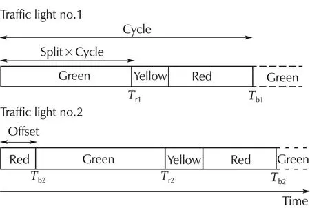
Fig.2 A schematic of the traffic signal control.
In this paper,it is assumed that traffic signal information such as the cycle,the split,the offset and the positions of the traffic lightsXdi(subscriptiis the index for the traffic lights)are available for the vehicle.Tridenotes the time atwhich the phase ofthe traffic signalwill change from green to yellow in the nearestfuture andTbidenotes the time at which the phase of the traffic signal will change from red to green in the nearest future.TriandTbiare calculated by the on-board computer using available traffic signal information.
2.2 Vehicle dynamics
A conceptual diagram of the hybrid electric vehicle model(HEV)is shown in Fig.3.The power-split device is the key component of the power-split HEV system and has both functionality of a speed coupler and a continuously variable transmission(CVT).There are five dynamic components:the engine,the battery,two motor/generators(M/Gs),and the wheels in this powersplitHEV system.The M/G1 is utilized to shiftthe engine operating points to the engine best efficiency line during various road loads.
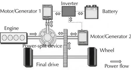
Fig.3 Model of the hybrid electric vehicle.Diagram adapted from[15].
The system dynamics can be represented by the battery dynamics,which can simplify the nonlinear MPC algorithm for implementation.This simplification is possible because we introduce four constraints:the road load;the torque and speed relationships of the speed coupler;the power flow relationships among the five dynamic components;and the engine optimal operating line(OOL)using CVT.We divided the system model into two levels.The high-level model is the slow dynamic battery model;and the low-level model contains the quick dynamic engine and M/Gs models.
The property of the power-split device,which reveals the torque and speed relationships among the engine,M/Gs,and the road load,can be expressed as follows[16]:

whereSandRare the number of the sun gear and the ring gear teeth,respectively;τM/G1,τM/G2,τreq,and τengare the torque of M/G1,M/G2,the road load,and the engine,respectively;ωM/G1,ωM/G2,and ωengare the angular velocities of M/G1,M/G2,and the engine,respectively;andgfis the final drive gear ratio.
The power flow relationships among the five dynamic components at the inverter and the power-split device are given as

wherePbatt,PM/G1,PM/G2,Peng,andPreqare the power of the battery,M/G1,M/G2,the engine,and the road load,respectively.
We assume that the engine always works along its OOL using CVT which can also be considered as a constraint.When the control input which is the battery power is known,using(2)the engine power can be obtained assuming the required power of the vehicle is known.When the engine poweris known,by looking up the table of OOL,the engine optimal speed and torque can be obtained.
We evaluate the fuel consumption using the Willan’s line method to reduce the complexity of the engine fuel consumption model.The HEV configuration in this work can realize idle stop using the electric CVT.It was found that a good approximation was obtained using the Willan’s line method[17].The fuel consumption rate can be calculated as

wherecfis a constant.The detailed explanation of this fuel consumption model is included in Appendix A.
The road load is known when the vehicle speed pattern is fixed.From the configuration of the power-split HEV system,the M/G2 speed is also known as

whererwis the wheel radius;andvreqis the required vehicle speed by the driving speed pattern.This driving cycle required vehicle speed is the desired value of the nonlinear model predictive controller.
When the driving speed pattern is unknown,the system dynamics includes the battery and the vehicle dynamics.Both the fuel economy and the driving profile are optimized.The system model is then represented by
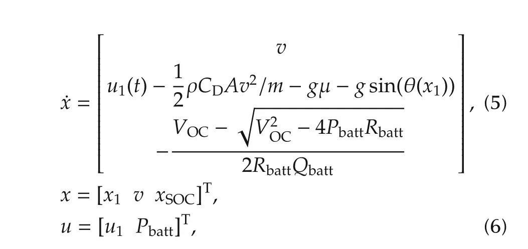
wherex1andvare the vehicle position and speed,respectively.xSOCis the battery SOC;ρ,CD,A,m,g,μ,and θ(x1)are the air density,the air drag coefficient,the frontal area of the vehicle,the vehicle mass,the gravity acceleration,the rolling resistance coefficient,and the road grade.u1is the vehicle acceleration or deceleration control input.
3 Controller design
3.1 Control scheme
In the case that the vehicle’s velocity is optimized considering all traffic signals,the size of the optimal problem becomes large.To cut down the size of the optimal problem,the proposed method deals with the furthest traffic signal which the vehicle is possible to pass through atthe currentvelocity.In this paper,model predictive method is used for the vehicle motion control since it enables to control the vehicle velocity predicting the states of the vehicle and traffic signal switching.Two model predictive controllers(MPCs)are formulated and the motion ofthe vehicle is controlled by switching them appropriately.
1)MPC1:based on the optimal control problem for vehicle cruising.MPC1 is designed for vehicle cruising at the velocity which the fuel consumption of the engine is the least.
2)MPC2:based on the optimal control problem for passing through the traffic lights timely.When MPC2 is used,the vehicle is controlled to pass through the target traffic light at the time when the phase changes with the least fuel consumption.
Fig.4 shows the proposed control scheme.The optimal input is obtained from MPC1 or MPC2 at each control cycle shown in Fig.4.u∗1andu∗2are the optimal inputs of MPC1 and MPC2,respectively.Eitheru∗1oru∗2is applied to the vehicle as control inputu.The detail about the controller selection algorithm is presented in Section 3.3.
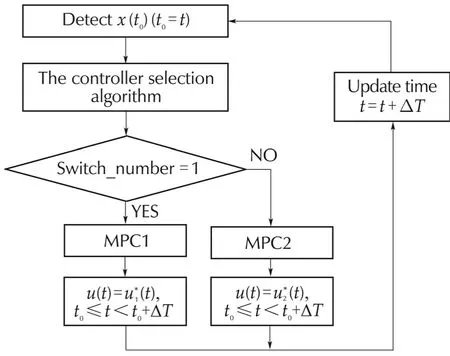
Fig.4 The proposed control scheme.Switch_number:index of the MPC(1:MPC1,2:MPC2),ΔT:control cycle.
3.2 Model predictive controller
The formulations of the two optimal control problems for MPCs are as follows:
MPC1:the performance index and the constraints of MPC1 are as follows:whereTis the prediction horizon.

The following objectives are considered in optimal control problem 1.
The termLx:the vehicle deceleration or acceleration is moderated.
The termL y:the vehicle speed is kept near to its desired value.
The termLz:the fuel economy is minimized.
The termLd:the battery SOC is kept near to its desired value.
The termLe:the battery energy is made best use of.This is one of the cores of the proposed approach.The battery energy is firstly used to satisfy the required road load.If it is not enough,the engine energy should be used,and the engine can work along its OOL.
The termLf:the battery SOC constraint is kept satisfied.
The cost functionLopt1is defined as follows:
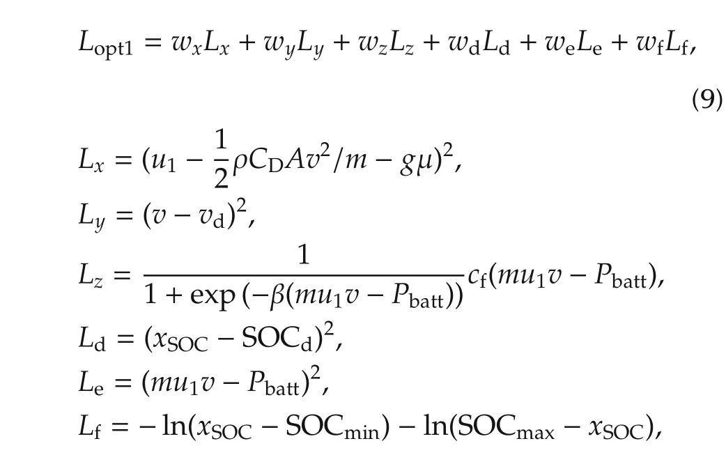
wherewx,w y,wz,wd,we,andwfare the weights,vdis the desired vehicle speed.SOCdis the desired battery SOC value.
MPC2:the performance index and the constraints for MPC2 are formulated as follows:

The following objectives are considered in optimal control problem 2.
Lg2:the term which evaluates the distance between the vehicle and the target traffic light.
Lh2:the term which evaluates the time distance between the vehicle and the target traffic light.
The definitions of other terms are the same as those in optimal control problem 1.
The cost functionLopt2is defined as follows:
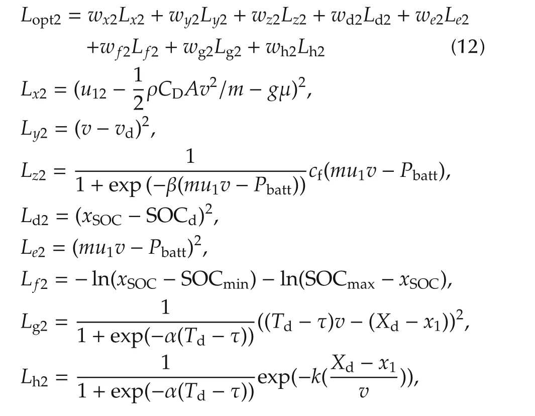
wherewx2,wy2,wz2,wd2,we2,w f2,wg2,andwh2are the weights.Tdis a timing when the phase of the target traffic signal changes(traffic signal switching time)andXdis the position of the target traffic light.kis a parameter deciding the shape ofLh2.The expression(Xd−x1)/vrepresents the time distance between the positionpand the target traffic light positionXdwhen the vehicle travels at the velocityv.Hence minimizing the cost functionLh2provides a smooth variation of the velocity.α is a parameter representing the shape of the sigmoid function.
3.3 Controller selection algorithm
The flow chart of the controller selection algorithm is shown in Fig.5.
This algorithm is executed att=nΔt(n=0,1,2,...).Δtis a control cycle.Fig.6 shows a typical function of the controller selection algorithm.The horizontal line segments in Fig.6 represent the red phases of the traffic signals.The solid line from the origin is the trajectory of the vehicle and the dashed line is the prediction trajectory of the vehicle.When the solid line of the trajectory crosses the horizontal line segments,the vehicle confrontsthe red phase ofthe traffic signal.Since the vehicle must stop in the red phase of the traffic signals,the solid line cannot cross any of the horizontal line segment.
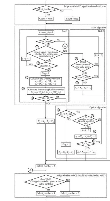
Fig.5 The flow chart of the controller selection algorithm.Count:a number of repeating the algorithm,next_signal:the upcoming traffic light number,xhat:predicted state of the vehicle position.
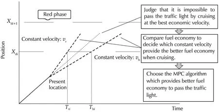
Fig.6 A schematic diagram of the controller selection algorithm.
Wcstis the fuel consumption rate when the vehicle is cruising and is approximated by the polynomials of the velocity as(13)[2].

whereb1,···,b4are the coefficients of the approximating polynomial.
If the possibility of confronting the red phase of the traffic signal is very low,the vehicle is controlled by the solution of MPC1.When the possibility that the vehicle informed traffic signalinformation from ITS passes atthe traffic lighttimely is low,MPC2 is employed.The feature of the proposed algorithm is to introduce evaluation of the fuel economy into the decision of the time to pass the traffic light.Hence the vehicle can be always controlled to get good fuel economy.There are two kinds of processing;the first case is that the phase of the traffic signal changes from green to yellow in the prediction horizon and the second case is that the phase of the traffic signal is red currently.The first processing for which the phase of the traffic signali(the traffic lights in front of the vehicle positionx1are considerable)change from green to yellow in the prediction horizon is as follows.
Part 1 of the main algorithm1)Detect the traffic lightiwhich is needed to be taken into account for estimating whether the vehicle can pass it during the prediction horizon or not.
2)Judge whether the vehicle can pass the traffic lightiduring the green phase or not.If it is judged that the vehicle can pass through the traffic lightitimely,iis incremented and back to step 1).If not,go to the next step.
3)Calculate the constant velocities at which the vehicle can pass the target traffic lightiusingTriandTbiatt.

4)Calculate the fueleconomies when the vehicle travels atvrorvbusing(13).

5)CompareMrandMband find the larger one.Then select MPC2 and set the parameters as follows:

The steps above are the main algorithm in Fig.5.IfMbgt;Mr,the next option algorithm is executed.
Option algorithm
6)Compare the setting distanceXt(VdT)and the distance between the traffic lightiandi+1.If the distance(Xi+1−Xi)is shorter thanXt,go to the next step.If not,select MPC2,set the parameters as(16)and then finish the algorithm.
7)Judge whether the vehicle can pass the traffic lighti+1 during the green phase at the constant velocityvror not.If the vehicle can pass,finish the algorithm.If not,go to the next step.
8)Calculate the velocity at which the vehicle can pass the traffic lighti+1 at the timeTri+1.

9)Comparevrand the vehicle’s admissible maximum velocityVmax.Ifvrlt;Vmax,iis incremented and back to the step 6.If not,select MPC2 and set the parameters as follows:

Such a case can be happened that even the vehicle accelerates up and had passed the target traffic light successfully,it has to consider that the vehicle stops at the next traffic light if the distance between the target traffic light and the next one is very near.The fuel is wasted in this case.Steps 6)–9)are produced to avoid waste of the fuel.
If the traffic lightiis in the red phase,the next algorithm is executed.
Part 2 of the main algorithmi)Judge whether the traffic lightiis in the red phase when the vehicle arrives at it.
ii)If the vehicle is expected to arrive at the traffic light in the red phase,the vehicle is controlled to pass the traffic light at the timeTbi.Then select MPC2 and set the parameters as follows:

If not,MPC1 is still used.
In the algorithm shown in Fig.5,when MPC1 is selected,all the traffic lights in front of the vehicle positionx1are checked.When MPC2 is selected,the traffic lights whose number satisfiesx1lt;XdiandiFlag are checked.MPC2 switches to MPC1 after the vehicle passes the target traffic light or after the phase of the target traffic signal changes to green.
The stability of the MPC is guaranteed by the use of the log barrier function,hence the terminal constraints are not imposed.
4 Computer simulation
Computer simulation was executed in order to confirm the effect of the proposed method.MATLAB and Simulink were used to conduct in computer simulation.C/GMRES[18]was used to solve the optimal control problem to obtain the optimal inputs.A brief description of the solution of the model predictive control problem using the C/GMRES method is included in Appendix B.The control algorithm is realized by utilizing the C MEX S-function builder in Matlab/Simulink.The fuel economy is calculated using the engine fuel consumption map which is obtained from ADVISOR 2002.
Tables 1 and 2 show the settings of the parameters of the vehicle specification and the controller.
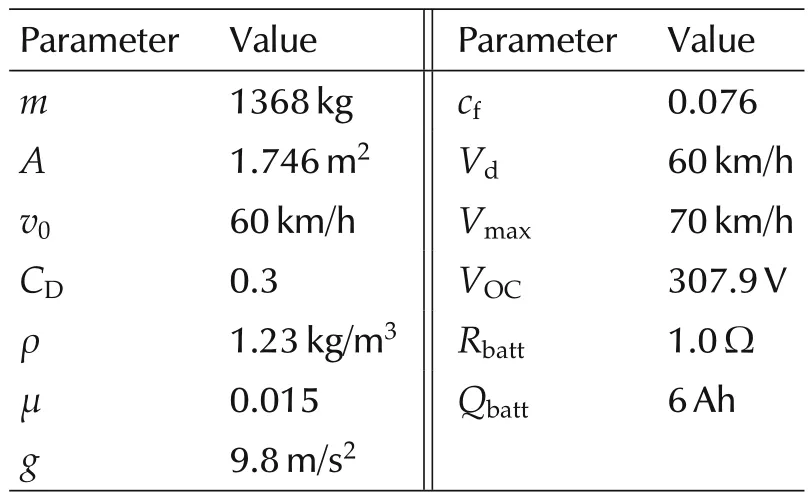
Table 1 The parameters of the vehicle.
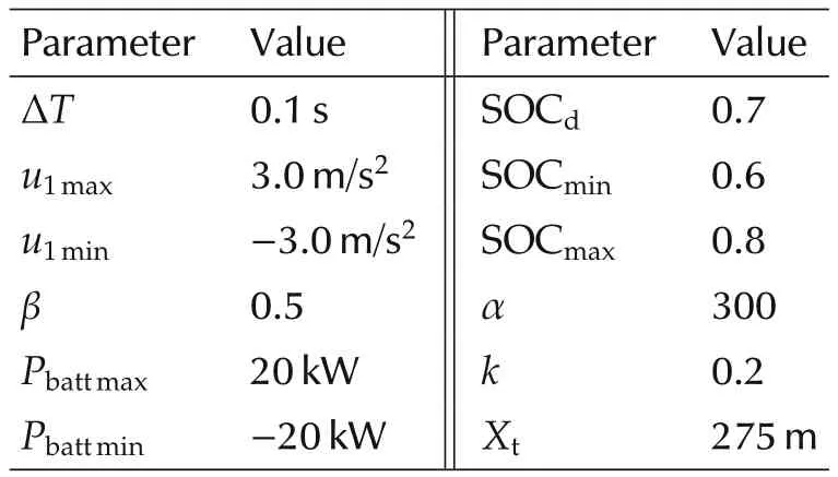
Table 2 The parameters of the controller.
The parameters of the traffic signals were set using real world data.The data was taken at Route 202 located in Fukuoka,Japan.We examined the traffic lights from the lights of By-Pass Aoki to the lights of Hatae at Route 202.There were 11 traffic lights,and the whole distance was about 6.2 km.The parameters of the 11 traffic signals were obtained through analyzing the videos which were recorded by cameras.The positions of the traffic lights were determined using digital maps.
It was assumed that there were no other vehicles on the road except the host vehicle.The motion of the vehicle controlled by the proposed method was compared with the motion produced by the Gipps model[19]by which the typical human driving was represented.The parameters of the vehicle driven by the Gipps model was the same as the ones in Table 2.
The target velocity of the Gipps model was set at the best economic velocity(60 km/h).The time histories of the motions are shown in Fig.7.Further,Fig.8 shows the road slope,the vehicle’s acceleration and its velocity of the motion of the proposed method and the Gipps model,and the battery SOC,respectively.The vehicle controlled by the proposed method did not stop at any of the traffic lights and the vehicle’s acceleration controlled by the proposed method was smaller than that of the Gipps model.
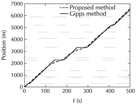
Fig.7 The trajectories of the proposed method and the Gipps model.
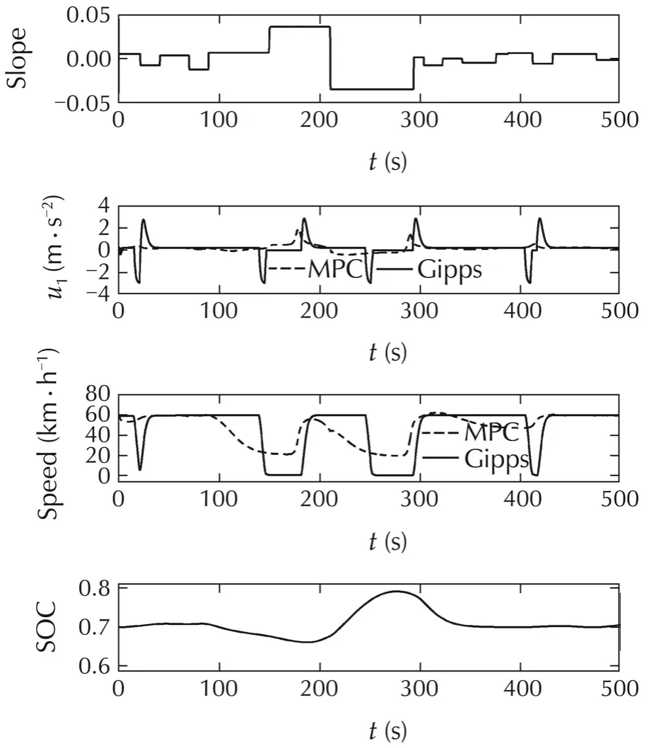
Fig.8 The result of the proposed method.
The simulation results showed thatthe MPC algorithm could use the road slope information well to reduce the fuel consumption.The vehicle accelerated before the upslope to make use of the kinetic energy.The battery recuperated vehicle braking power during the vehicle down slope driving.The vehicle using the MPC algorithm predicts the upcoming up-down hills and traffic lights,and avoids the abrupt acceleration or deceleration as shown in the Gipps method at the link parts of different slopes and the red periods of the traffic lights.There is some causality between the road elevation and the battery SOC.The lowest point of the road elevation corresponds to the highest point of the battery SOC.The highest point of the road elevation corresponds to the lowest point of the battery SOC.By using the slope and traffic light information in advance to better use the battery SOC range,the MPC algorithm helps to reduce the fuel consumption efficiently.
As a result after traveling 6200 m,the fuel economy of the vehicle using the proposed method was improved 1.79%,which was better than that of the Gipps model as shown in Table 3.

Table 3 The results of the fuel economy(km/l)after traveling 6200 m.
The effect of the fuel economy might change with different prediction horizon.To test the effect of the prediction horizon,the fuel economies were calculated in the simulation with different prediction horizon.The prediction horizon was set at 10 s to 160 s stepped by 10 s.The target velocity of the Gipps model was set at the best economic velocity(60 km/h).The fuel economy with different prediction horizon using the proposed method was shown in Table 4 and Fig.9.It is shown that the best fuel economy occurs when the prediction horizon equals to 140 s.The fuel economy fluctuates lightly when the prediction horizon is above 80 s.The battery dynamics which dominates the system dynamics is around 80 s.The best prediction horizon for the HEV is chosen as 140 s after balancing the computation burden and the system performance.
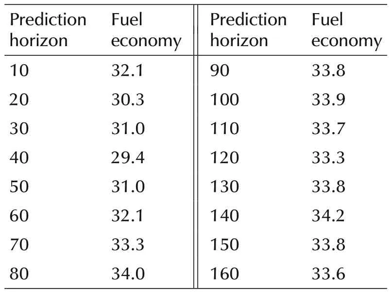
Table 4 The fuel economies(km/l)with different prediction horizon.
The proposed control algorithm is fast for computation.The computer simulation time for the HEV is 500 s.The computation time of the proposed control algorithm for the HEV is 137 s.The simulation is run in a Matlab/Simulink environment using a laptop with an Intel processor at 1.9 GHz processing speed and 4 GB of RAM.The sampling interval is 100 ms.The computation time per sampling interval of the proposed control algorithm for the HEV is 27 ms.Therefore,the proposed control algorithm has the potential for real-time vehicle control.
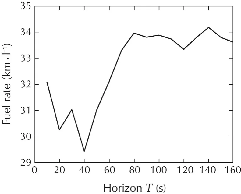
Fig.9 The relation between the fuel economies and the different prediction horizon.
5 Conclusions
We proposed a velocity control system in order to save the fuel consumption by involving traffic signal information.Model predictive control scheme was used in order to control the vehicle velocity predicting the states of the vehicle and traffic signal switching.The two model predictive controllers were formulated.The one was for vehicle cruising and another was for vehicle passing through the traffic lighttimely.The motion ofthe vehicle was controlled by switching them appropriately to travel at all times in the good fuel economy.We designed the algorithm to judge whether a vehicle should accelerate ornotwhen the vehicle cannotpass the traffic lights during the green phase.In the algorithm,the fuel economy was predicted using traffic signal information.Computer simulation was also demonstrated.The control parameters of the traffic signal were set examining the real traffic lights on Route 202.The fuel economy using the proposed method was improved the fueleconomy of the Gipps model which the target velocity was the best economic velocity.The proposed approach can optimize both the fuel economy and the driving profile.The approach is able to be implemented on real vehicles if the traffic information,the surrounding vehicle information,the road information,and so on are provided.
In the future,we will focus on an extension of the problem to the situation including road curves,speed limits of road sections,road bumps,and the motion of surrounding vehicles.
[1]E.Hellstom,M.Ivarsson,J.Aslund,et al.Look-ahead control for heavy trucks to minimize trip time and fuel consumption.Control Engineering Practice,2009,17(2):245–254.
[2]M.Kuroki,M.Mukai,J.Murata,et al.Vehicular model predictive control for optimal fuel consumption based on engine map.Proceedings of the 28th Kyushu Annual Congresses of the Society of Instrument and Control Engineers,Fukuoka,Japan,2009:29–30(in Japanese).
[3]M.Kamal,M.Mukai,J.Murata,et al.Ecological vehicle control on roads with up-down slopes.IEEE Transactions on Intelligent Transportation Systems,2011,12(3):783–794.
[4]C.Zhang,A.Vahidi,P.Pisu,et al.Role of terrain preview in energy management of hybrid electric vehicles.IEEE Transactions on Vehicular Technology,2010,59(3):1139–1147.
[5]K.Yu,J.Yang.Performance of a nonlinear real-time optimal control system for HEVs/PHEVs during car following.Journal of Applied Mathematics,2014:DOI 10.1155/2014/879232.
[6]K.Yu,M.Mukai,T.Kawabe.Model predictive control of a powersplit hybrid electric vehicle system.Artificial Life and Robotics,2012,17(2):221–226.
[7]K.Yu,M.Mukai,T.Kawabe.A battery management system using nonlinear model predictive control for a hybrid electric vehicle.Proceedings of the 7th IFAC Symposium on Advances in Automotive Control,Tokyo:Elsevier,2013:301–306.
[8]M.A.S.Kamal,M.Mukai,J.Murata,et al.On board ecodriving system for varying road-traffic environments using model predictive control.IEEE Multi-Conference on Systems and Control,Yokohama:IEEE,2010:1636–1641.
[9]T.Kawabe,M.A.S.Kamal,M.Mukai,et al.Model predictive control for ecological platoon driving.Proceedings of the JSAE Annual Congress(Autumn),Sendai,Japan:JSAE(Society of Automotive Engineers of Japan),2009:19–22.
[10]M.Barth,K.Boriboonsomsin.Energy and emissions impacts of a freeway-based dynamic eco-driving system.Transportation Research Part D,2009,14(6):400–410.
[11]Y.Saboohi,H.Farzaneh.Model for developing an eco-driving strategy of a passenger vehicle based on the least fuel consumption.Applied Energy,2009,86(10):1925–1932.
[12]B.Zhou,J.Cao,X.Zeng,et al.Adaptive traffic light control in wireless sensor network-based intelligent transportation system.Proceedings of the 72nd Vehicular Technology Conference,Ottawa:IEEE,2010:1–5.
[13]B.Asadi,A.Vahidi.Predictive cruise control:utilizing upcoming traffic signal information for improving fuel economy and reducing trip time.IEEE Transactions on Control Systems Technology,2011,19(3):707–714.
[14]Japan Society of Traffic Engineers(JSTE).Manual on Traffic Signal Control.Revised ed.Tokyo:JSTE,2006.
[15]J.Liu,H.Peng.Modeling and control of a power-split hybrid vehicle.IEEE Transactions on Control Systems Technology,2008,16(6):1242–1251.
[16]M.Ehsani,Y.Gao,A.Emadi.Modern Electric,Hybrid Electric,and Fuel Cell Vehicles:Fundamentals,Theory,and Design.2nd ed.Boca Raton,FL:CRC Press,2009:117–136.
[17]G.Rizzoni,L.Guzzella,B.Baumann.Unified modeling of hybrid electric vehicle drivetrains.IEEE-ASME Transactions on Mechatronics,1999,4(3):246–257.
[18]T.Ohtsuka.A continuation/GMRES method for fast computation of nonlinear receding horizon control.Automatica,2004,40(4):563–574.
[19]P.G.Gipps.A behavioural car-following model for computer simulation.Transportation Research Part B,1981,15(2):105–111.
Appendix
A.Engine fuel consumption model
The proposed engine fuel consumption modeling method is a special method using both Willan’s line method[17]and the assumption of operating the engine along the engine optimal operating line,and is introduced as follows.The HEV parameters are used from the ADVISOR 2002 Toyota Prius HEV data.
In[17],the Willan’s line model consists of an affine representation relating the available energy,that is,the energy that is theoretically available for conversion,to the useful energy that is actually present at the output of the energy converter.Formally

where the parametererepresents the peak intrinsic energy conversion efficiency of the converter,andWlossrepresents external(parasitic)losses.In fact,this model of energy conversion efficiency is nonlinear,in that the parameterseandWlossare represented as explicit functions of the output flow variable(e.g.,engine speed)and are also implicit functions of the effort variable.
The modelling method given above is for general engines.However,in this work,the electric CVT can realize idle stop,and soWlossbecomes zero.When it is assumed that the engine operating points are maintained at the best efficiency,the parametersecan be approximated as a constant.In this case,the fuel consumption rate corresponding to the optimal operating line can be fitted using a linear function.
The engine optimal operating line can be plotted on the engine map as shown in Fig.a1.The engine optimal operating points provide the highest efficiency for a given power level.The engine best efficiency related to the engine power according to the engine characteristics is shown in Fig.a2.
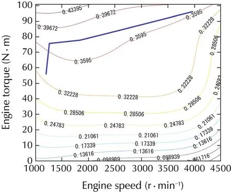
Fig.a1 The engine efficiency map to the best engine operating points.
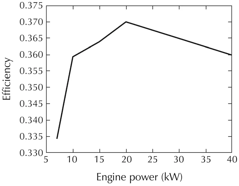
Fig.a2 The engine efficiency curve to the bestengine operating points.
The fuel consumption rate is estimated as(see Fig.a3)

whereCis the calorific value of the gasoline,which is equal to 34.5 × 10⁶J/l,and η is the engine efficiency.
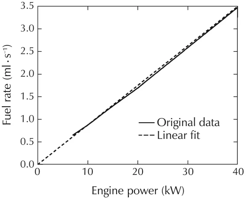
Fig.a3 The engine fuel consumption rate to the best engine operating points.
B.Solution of the model predictive control problem
A brief description of the solution of the model predictive control problem is provided as follows.
To implement the model predictive control algorithm,the horizonTis divided into N steps,and the optimal control problem is discretized.The general discretized optimal control problem is formulated as

whereuis the controlinput,xis the state,Lis the costfunction.f(x,u)is the state equation.G(x,u)is the inequality constraint.
The inequality constraint in the optimal control problem is converted to an equality constraint by introducing a dummy inputudfor computation simplicity as follows:

whereumaxdenotes the upper bound of the control input.
To solve this optimal control problem with the calculus of variation method,the Hamiltonian function is defined by

where λ denotes the co-state,and ψ denotes the Lagrange multiplier associated with the equality constraint.
The first-order necessary conditions for the optimal control inputu,the multiplier ψ,and the co-state λ are obtained using the calculus of variation as

wherex0is the initial state.
To solve this optimal control problem,the continuation and GMRES(C/GMRES)method is employed for computation cost reduction.The necessary conditions of optimality for the constrained control input can be expressed as the following equations:
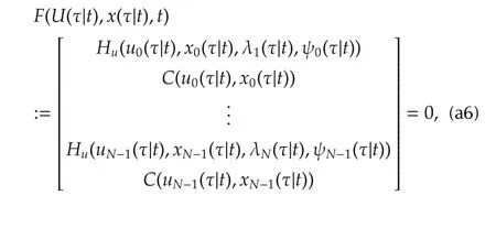

F(U(t),x(t),t)=0 is identical to

whereAsis a stable matrix introduced to stabilizeF=0.IfFUis nonsingular,a differential equation forU(t)can be obtained as

The above differential equation can be solved by the GMRES method.The presented approach is also a kind of continuation method.The solution curveU(t)is traced by integrating the above differential equation.Because there is no need to calculate the Jacobians and the linear equation iteratively,C/GMRES method assures the realtime optimalcontrolability because of small computational cost.The detailed description of the solution for the model predictive control algorithm can be found in[18].

his Ph.D.degree from Kyushu University in Electrical and Electronic Engineering,Japan,in 2013.He is currently a lecturer of College of Electrical Engineering and Automation,Henan Polytechnic University,Jiaozuo,China.His research interests include HEV energy management and model predictive control.E-mail:yu.kaijiang@163.com.

Junqi YANGreceived his Ph.D.degree in Control Theory and Control Engineering from Tongji University,Shanghai,China,in 2013.He is currently a lecturer of College of Electrical Engineering and Automation,Henan Polytechnic University,Jiaozuo,China.His current research interests include the areas of state estimation,modelbased faultdetection,and fault-tolerantcontrol.E-mail:yjq@hpu.edu.cn.

Daisuke YAMAGUCHIreceived his M.E.degree from the Department of Electrical Engineering,Kyushu University,Japan,in 2011.His research interests include receding horizon control and its applications.E-mail:yamaguci@cig.ees.kyushu-u.ac.jp.
†Corresponding author.
E-mail:yu.kaijiang@163.com.Tel.:+86-18539132549;fax:+86-391-3987552.
This work was supported by National Natural Science Foundation of China(Nos.51405137,61403129),the Key Scientific Research Program of the Higher Education Institutions of Henan Province(No.15A470014),the Program for Innovative Research Team of Henan Polytechnic University,and the Doctoral Program Foundation of Henan Polytechnic University.
©2015 South China University of Technology,Academy of Mathematics and Systems Science,CAS,and Springer-Verlag Berlin Heidelberg
杂志排行
Control Theory and Technology的其它文章
- Variable selection in identification of a high dimensional nonlinear non-parametric system
- Identification of integrating and critically damped systems with time delay
- Immersion and invariance adaptive control of a class of continuous stirred tank reactors
- Pinning synchronization of networked multi-agent systems:spectral analysis
- Discrete-time dynamic graphical games:model-free reinforcement learning solution
- Topology-preserving flocking of nonlinear agents using optimistic planning
