Analysis and modeling of hysteresis of piezoelectric micro-actuator used in high precision dual-stage servo system
2015-12-05MdArifurRAHMANAbdullahAlMAMUNKuiYAO
Md.Arifur RAHMAN ,Abdullah Al MAMUN ,Kui YAO
1.Department of Electrical and Computer Engineering,National University of Singapore,4 Engineering Drive 3,Singapore 117576;
2.Institute of Materials Research and Engineering,A*STAR(Agency for Science,Technology and Research),3 Research Link,Singapore 117602
Received 30 October 2014;revised 24 March 2015;accepted 25 March 2015
Analysis and modeling of hysteresis of piezoelectric micro-actuator used in high precision dual-stage servo system
Md.Arifur RAHMAN1†,Abdullah Al MAMUN1,Kui YAO2
1.Department of Electrical and Computer Engineering,National University of Singapore,4 Engineering Drive 3,Singapore 117576;
2.Institute of Materials Research and Engineering,A*STAR(Agency for Science,Technology and Research),3 Research Link,Singapore 117602
Received 30 October 2014;revised 24 March 2015;accepted 25 March 2015
A dual-stage servo system consists ofa primary coarse actuatorforfacilitating large motion and a secondary micro-actuatorfor small but precise motion to improve tracking performance.Piezoelectric micro-actuator made from lead zirconate titanate(PZT)has been a popular choice for the secondary stage.However,the advantage gained by the resolution of the secondary PZT actuator is reduced by its inherent hysteresis nonlinearity.Model based hysteresis compensation techniques are preferred due to their simplicity and fast response.Identification and modeling are two substantial parts in such model-based techniques.This paper presents a rigorous analysis and modeling of the hysteresis of PZT micro-actuator.Modified Generalized Prandtl-Ishlinskii and Coleman-Hodgdon models are studied.Identification of the model through nonlinear least square and particle swarm optimization are examined and compared.Several analyses are done through tuning of the model parameters and identification techniques.Experimental analysis and simulation results underscore the effectiveness of this modeling approach.Finally as a design example,a dual-stage simulation analysis is done to show the effectiveness of systematic modeling on hysteresis compensation.
Hysteresis,particle swarm optimization(PSO),modified generalized Prandtl-Ishlinskii(GPI),inverse GPI
DOI 10.1007/s11768-015-4150-2
1 Introduction
High precision servo system finds its application in a wide range of fields such as semiconductor manufacturing,precision engineering,information technology and biomedicaltechnology.Research developing in such systems has reached an inter-disciplinary status involving areas ofsensortechnology,actuatortechnology,materials science,control system etc.Continuing demand for higher precision and higher accuracy in precision systems require higher bandwidth and higher robustness.Usage ofdual-stage actuatorhas become the normin the fields of high precision servo system.In DSA,a coarse actuator is used for longer range of motion while a fine actuator is used to achieve sub-nanometer scale accuracy but in a shorter range of motion.The fine actuator provides the high bandwidth as demanded.The Piezoelectric micro-actuator made from lead zirconate titanate(PZT)is a popular choice as the fine actuator in DSA.However,the PZT actuator shows nonlinear behavior in the form of hysteresis.This hysteresis has detrimental effects on the accuracy and thus limits the level of performance of the servomechanism.The hysteresis in PZT actuator not only introduces inaccuracy but also produces oscillations that may even lead to instability of the closed loop system[1].
Different model-free techniques,like adaptive techniques for compensating hysteresis are reported in the literature[1–3].Hysteresis of the piezoelectric actuator can also be reduced if the charge amplifier is used instead of voltage amplifier[4,5].This method is based on linearrelationship between charge and displacement.But due to its complexity in design,the method has not become so popular in the research community.
Model based compensation techniques are popular among control community due to its simplicity and fast response.A number of models have been reported in literature to describe the hysteresis behavior of smart actuators and thereby designing the compensator to overcome the hysteresis effects[6,7].These models can be classified into physics-based models[6]and phenomenological models[8–10].The physics-based models are generally derived on the basis of a physical measure,such as energy,displacement,or stress-strain relationship.On the other hand,phenomenological models are mainly based on input-output data extracted from experiments.A number of phenomenological models have been proposed to describe hysteresis.These include Preisach model[8],the Krasnosel’skii-Pokrovskii model[10],Bouc-Wen model[11,12],the Prandtl-Ishlinskii(PI)model[13]etc.Besides,several other new modeling techniques like ellipse based model[14]can also be found in literature.
The classical PI model,a popular phenomenological hysteresis model,is defined as the superposition of elementary play orstop operators.These play operators are parameterized by a single threshold variable.It should be noted that classical PI and Preisach models are subsets of the same class that consists in modeling the hysteresis with hysteron.One limitation of the classical PI model is that it cannot exhibit either asymmetric hysteresis loops or saturated hysteresis output[15,16].The density function or the envelope function of the classical PI model can be modified and the play operator or stop operator can be re-defined to enhance the ability to describe hysteresis.In order to fully exploit such an advantage,a generalized play hysteresis operator can be applied to the PI-model in conjunction with the density function and envelope function to characterize accurately the hysteresis nonlinearity in smart actuators[17].
Any model-based compensation technique can be divided into three parts:i)analyzing the system behavior,ii)modeling the behavior,and iii)compensation or control.This paper addresses the first two parts of the model-based compensation.A rigorous analysis and an efficient modeling of the hysteresis in PZT microactuator are presented.It is obvious that the more accurate is the modeling,the more efficient will be the compensation.Efficient and exact modeling will lead to a decrement of overall system design complexity.This reduction in system design complexity increases the designed controller performance.The first step for obtaining an accurate model is to analyze the hysteresis behavior of the system.Once the hysteresis behavior is studied,the identification is done to obtain an exact hysteresis model.An optimized and efficient identification technique can guarantee the precise modeling.Therefore,the focus of this paper is to establish a strong methodology forthese two parts:analysisand modeling.Two different hysteresis models are considered in this paper:i)Modified Generalized Prandtl-Ishlinskii(GPI)model,and ii)Coleman-Hodgdon model.Their performances are compared in terms of the fitness of their responses with the experimental data.Two optimization methods are used in this work:i)particle swarm optimization(PSO),and ii)nonlinear least square method(NLS).Optimization performance is also evaluated for each method.From two different methods and optimization techniques,the best suitable methodology for identification can be obtained conveniently.Finally to show the effectiveness of hysteresis controller,a dualstage simulation analysis is presented.This part shows the performance improvement when the accurate modeling is done.
A dual-stage hard disk drive(HDD)is taken as the experimental platform in this paper and hysteresis behavior of the secondary piezoelectric micro-actuator is studied.In hard disk drives(HDDs),information bits are recorded in concentric data tracks on rotating disks.The R/W head is used for recording as well as retrieving recorded bits from the disk.The R/W head is fabricated on a single piece of slider.The slider is positioned on the tracks by a head-positioning servomechanism.This servo-system has two modes of operation:track seeking and track following.In track-seeking mode,the head is moved from one track to another track in minimum possible of time.In track-following mode,minimum position error signal is desired which means that head should be maintained as close as possible to the center of the track.Nowadays,HDD servomechanism uses dual-stage actuation.The dual stage HDD consists of a voice coil motor(VCM)and a PZT secondary actuator(PSA).VCM consists of a coil suspended in the magnetic field produced by the permanent magnets.VCM is used to provide coarse motion and PSA is used for fine positioning.The dual-stage HDD is shown in Fig.1.
The paper is organized as follows.Frequency response and hysteresis analysis are presented in Section 2.Phenomenological models of the hysteresis nonlinearity are identified using different approaches.Identification results are compared between different optimization techniques.These are given in Section 3.Construction of nonlinear PZT model is presented in Section 4.Design of dual-stage servo control is presented in Section 5 and simulation results are presented in Section 6.Conclusion of the findings and scope of future works are given in Section 7.
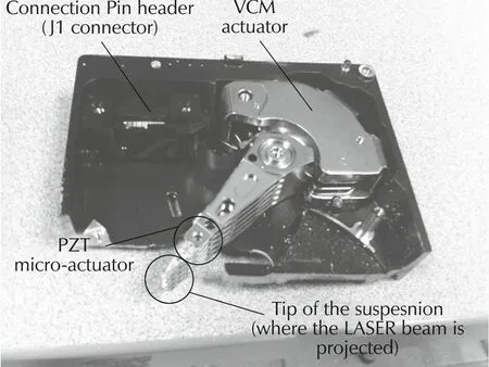
Fig.1 Dual-stage hard disk drive.
2 Frequency response and hysteresis analysis
Hysteresis is considered as dominant nonlinearity of PZT actuator.The focus of this work is to do a rigorous analysis of hysteresis.In order to find the existence of hysteresis nonlinearity,sufficient analysis needs to be carried out on experimentally acquired data.The details of these analyses are included in this section.All the analyses are carried outby using the data in time domain and frequency domain,obtained from the experiment.A best-fit linear model of the micro-actuator is identified from measured frequency response.Hysteresis analysis is done using time-domain data obtained for sinusoidal excitation signalofdifferentfrequenciesand amplitudes.VCM actuator frequency response is also obtained and identified for the dual-stage performance evaluation.
2.1 Experimental setup
As said earlier,PZT micro-actuator and VCM actuator used in this work are obtained from a dual-stage hard disk drive available in the market.The experimental setup is shown in Fig.2.A laser Doppler vibrometer(LDV)is used to measure the displacement of the read/write head slider attached at the tip of the suspension.Resolution of LDV is set to 50 nm/V and the gain of the PZT amplifier is set to 20.The input signal is generated either by the dynamic signal analyzer(DSA)from the National Instruments(NI)or by a dSPACE 1104 card inserted in a PC.While measuring the frequency response,the sweep sine signal generated by the DSA is used as the input.All computations required to generate frequency response data is also carried out in the DSA.The dSPACE card,on the other hand,is used to produce input signals required for time-domain data acquisition and also for implementation of real-time controller.
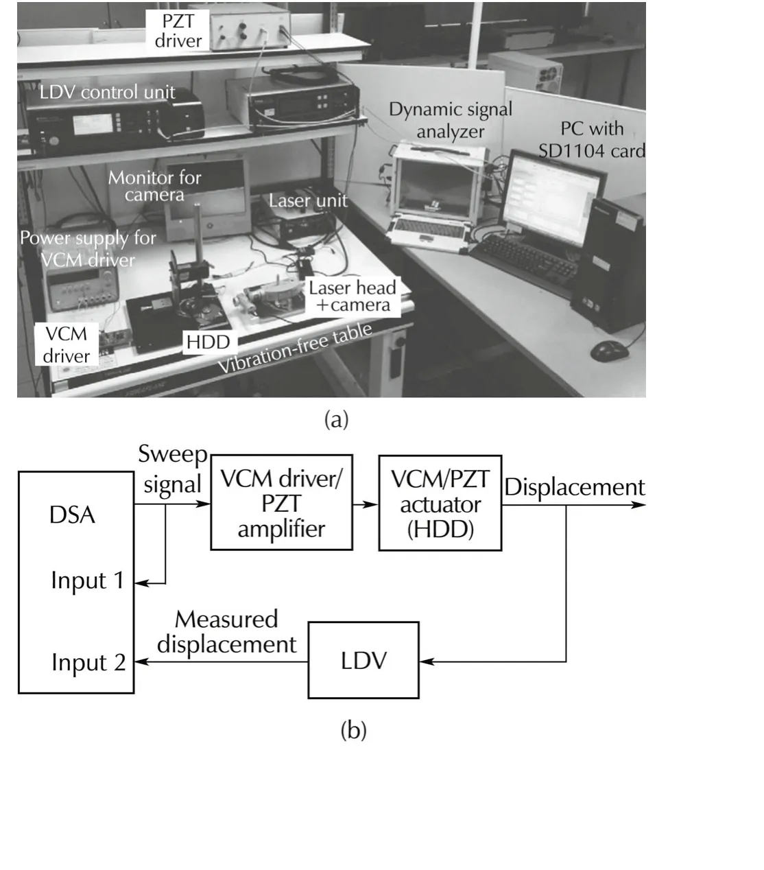
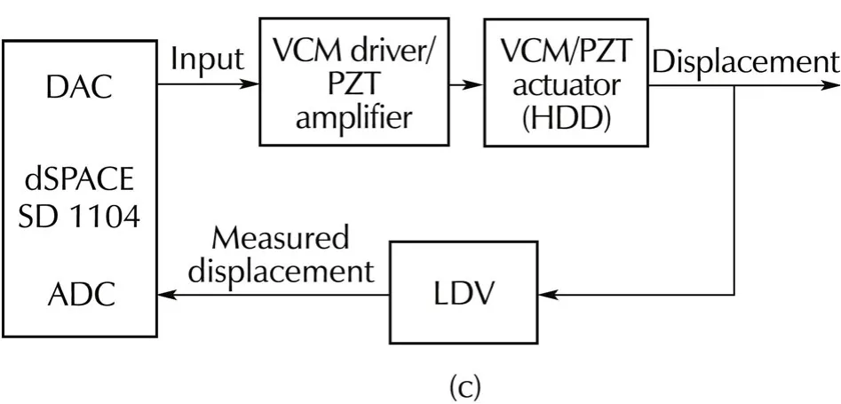
Fig.2(a)Experimental setup.(b)Frequency response experiment.(c)Hysteresis identification experiment.
2.2 Frequency response and linear model identif ication
LabVIEWTMfrequency response analyzer code generates the excitation signal(sweep sine)applied to the VCM driver circuit or PZT amplifier.The same signal is also connected to one of the input channels of DSA.The displacement signal from the LDV is connected to the second input channel of DSA.The analyzer produces the frequency response data,and the result is saved for further processing.
2.2.1 VCM plant model
From the measured frequency response,VCM actuator can be modeled as a double-integrator for the lower frequency with few resonant modes in the high frequency.Therefore,the VCM plant model is of the following form:

whereKvis the gain;andNvis the number of mechanical resonant modes modeled.A∑-type model is used for the mechanical resonances where each mode is modeled using a pair of lightly damped complex conjugate poles.Three parameters(Ai,ωriand ζi)are to be identified for each resonant mode,

The parameters of the rigid body model(doubleintegrator)and the resonant mode model are identified using the method given in[18–20].General guidelines for constructing a∑-type model are
.Considerthe modes with largergain before proceeding to the modes with the smaller gain.
.Set the modal angular frequency ωrito match the frequency of the peak gain.
.Tune the modal damping ratio ωriby using the half value method in order to fit frequency-width of the peak gain at half of the maximum and shape of phase change and adjust the absolute value and sign of the residueAito match the peak gain and direction of phase change in the data,respectively.
The experimental frequency response and the response of the identified VCM model are shown in Fig.3.Here transport delay is not considered.The identified parameters of(1)and(2)are shown in Tables 1 and 2.
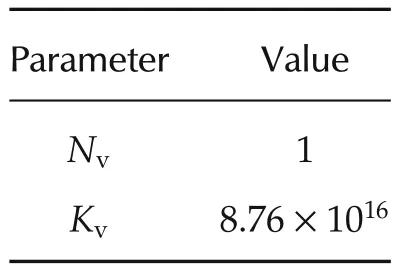
Table 1 Parameter values of GV(s).

Table 2 Parameter values of Hri.
2.2.2 PZT plant model
Similar to the identification of VCM plant model,a frequency response experiment is done for PZT model identification.The obtained experimental frequency response data is then used to identify a linear model of the PZT micro-actuator.The identified model is in the form of

whereKpis the gain;andNpis the number of mechanical resonant modes of PZT micro-actuator.Each mode is identified as

The identified parameters of(3)and(4)are presented in Tables 3 and 4.The response of the identified PZT model is also shown in Fig.3.
Remark 1The measured frequency response relates an input signal measured in volts(V)to an output signal also measured in volts(V).Therefore,the transfer function is unit-free.The output signal can be converted into displacement unit by multiplying it by the scaling factor of 50 nm/V.
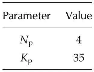
Table 3 Parameter values of GP(s).
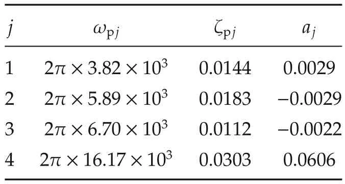
Table 4 Parameter values of R j.
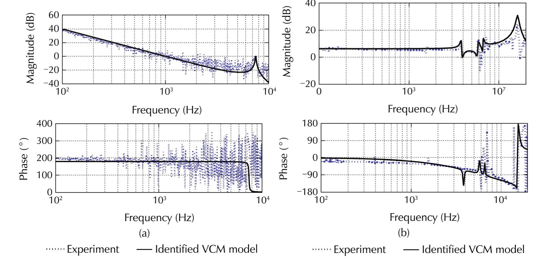
Fig.3 Frequency response and Identified model for(a)VCM actuator and(b)PZT micro-actuator.
2.3 Hysteresis analysis in PZT micro-actuator
Hysteresis of the PZT micro-actuator is studied using time-domain input-output(I/O)data.Data is acquired using dSPACE 1104 card.Sinusoidal signal generated by the host PC is applied through card to the PZT amplifier and the corresponding output signal obtained from the LDV is captured.Data is captured for different amplitudes and different frequencies of the input signal.The sampling interval is set to 25μ s.
2.3.1 Hysteresis at different frequencies
Hysteresis is non-vanishing input-output loop at asymptotically low frequency which is an inherent nonlinear characteristic of the system.For high frequency inputsignal,the effectofphase lag introduced by the linearsystem on the hysteresisbecomes significant.Therefore,low frequency signal should be used to generate data for hysteresis analysis.Data are captured for differentfrequencies ofinputsinusoid to understand how low the frequency should be to analyze hysteresis behavior.In this section the hysteresis characteristics are examined at different frequencies of the input sine wave.The amplitude of the sine wave is kept at 10 V for all experiments of this stage.
Simulated input-output loops obtained from the identified linear model are also examined.These observations,both experimental and simulated,at four different frequencies(100 Hz,200 Hz,400 Hz and 500 Hz)are shown in Figs.4 and 5,respectively.In Fig.5,smaller phase-lags are observed from linear model response for smaller frequencies.This linear model results in negligible input-output loop at 100 Hz and 200 Hz.Furthermore,the I/O loop obtained from the linear model becomes a straight line at input frequency of 100 Hz.Therefore,data acquired with 100 Hz input sine wave is used for hysteresis analysis and model identification.This can be further analyzed by a mathematical analysis as follows.

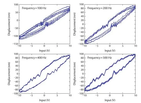
Fig.4 Input-output response of PZT micro-actuator at different frequencies obtained from experiment.
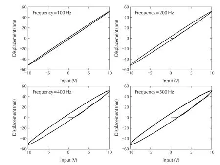
Fig.5 Input-output response of PZT micro-actuator at different frequencies from linear model.
2.3.2 Hysteresis at different amplitudes
Hysteresis is an amplitude-dependent phenomenon,which must be taken into account when generating data to be used for hysteresis analysis.Data are acquired with different amplitudes(6 V,8 V and 10 V)of input sine wave of 100 Hz.The frequency is decided according to the results given in the previous section.The I/O loops for all these experiments are shown in Fig.6.The responses of the linear model are also shown.
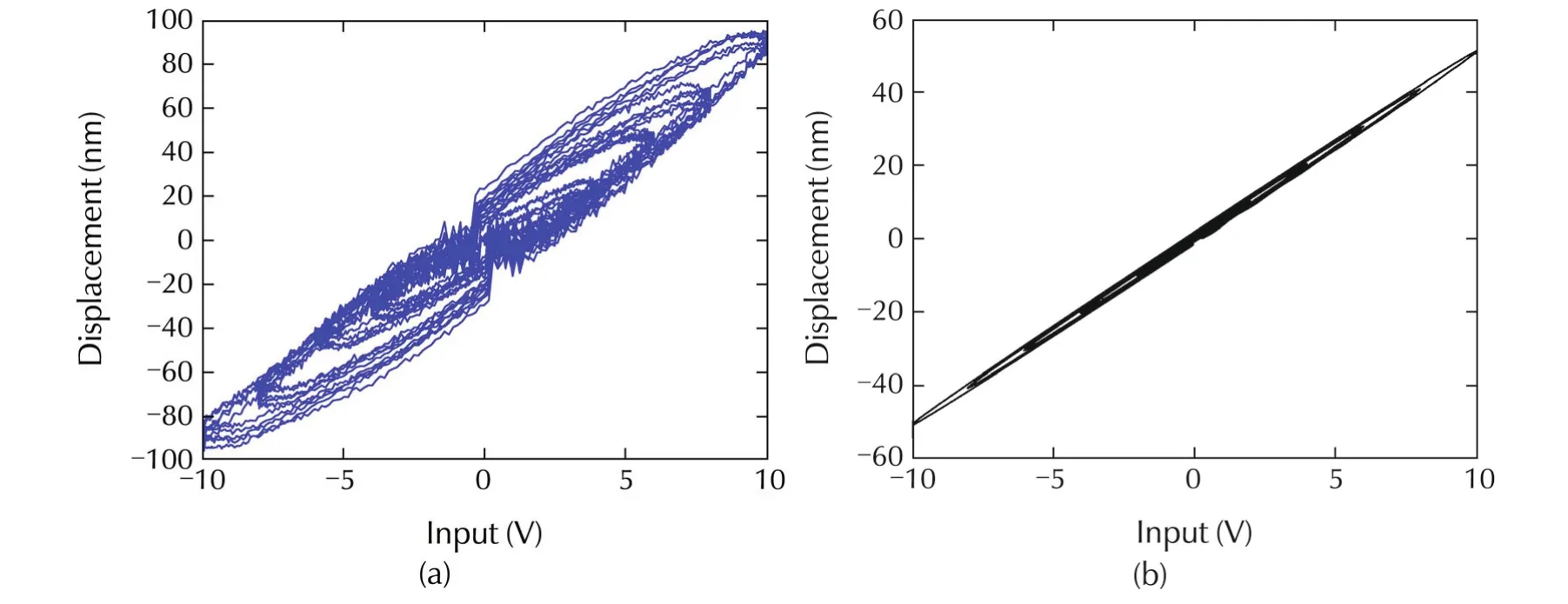
Fig.6 Input-output response of PZT micro-actuator for different amplitudes of 100 Hz sine wave input:(a)experimental results and(b)responses of the linear model.
3 Modeling of hysteresis in PZT
Phenomenological models are well suited to describe the physical hysteresis in different smart actuators.These models are more suitable to be identified from experimentally obtained input-output data.Many phenomenological models are proposed in the literature.Two such models,namely,i)GPI model[17]and ii)Coleman-Hodgdon model[21],are studied in this paper.In order to obtain better accuracy in model identification,GPI model is slightly modified in this work.A comparison is also done between modified GPI model and Coleman-Hodgdon model.Two different methods are used for estimating model parameters.These are i)NLS and ii)PSO.
3.1 Modified GPI hysteresis model
The details of hysteresis play operator and GPI model are discussed in[17].The classical PI hysteresis model has a limitation as it is applicable to symmetric hysteresis loop only.That limitation is overcome in the GPI model,and therefore GPI model can be used to model the input-output relationships of the PZT actuators.In this work,the envelope functions of the GPI model is changed to obtain better accuracy in identification.
The modified GPI model is in discrete form which makes the use of generalized play operators and is described as

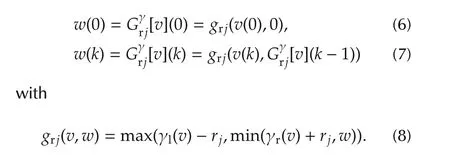
The density function pjand envelope functions γland γrare

with rj=ρj and j=1,2,3,...,n.
q,α,β,ρ,μl,μr,φl,φr,θl,θrare the parameters to be estimated from the experimental data.Block diagram of GPI model is shown in Fig.7.
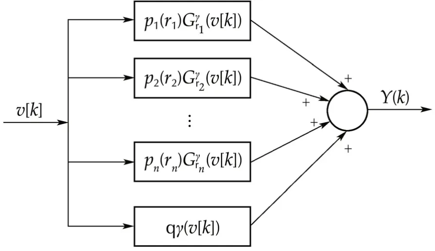
Fig.7 Block diagram of GPI model.
3.1.1 Identification of modified GPI model parameters
Despite being relatively mature and well-developed,conventional parameter estimation tools in system identification,such as least mean square(LMS),nonlinear least square(NLS)etc.have many limitations.In these methods initial parameter choice is an important factor.If the parameter initialization is not appropriately done,then the algorithm may result in poor optimization or sometimes convergence may not occur.Besides,these methods may trap in the local minima and may give local solutions.These algorithms also do not accept bound constraints on the parameters.Therefore,other approaches have been developed for nonlinear model identification.Artificial neural network(ANN)and Genetic algorithm(GA)are two examples of many such approaches reported in the published literature[22–25].ANN and GA have their drawbacks in the form of design complexity and slow convergence rate.ANN is also prone to being trapped in the local optimum.On the other hand,PSO ensures the convergence of the model parameters to the global optimum and it is much simpler to design.PSO is a population based optimization technique based on the intelligence of swarms[21,26].It was first developed in 1995 and it uses the concept of social interaction for problem solving.In PSO,a number of particles constituting the swarm move around in the search space for the optimum solution and each particle adjust its flying status according to its own flying experience aswellas the flying experience ofotherparticles.PSOis a derivative free optimization technique with faster convergence rate;making it suitable and efficient for estimating model parameters from noisy experimental data.In this paper,parameters of the modified GPI model of PZT micro-actuator hysteresis is estimated using PSO and the results are compared with the model identified using NLS method.
Identification(Nonlinear least square method)Nonlinearleast-square function of the optimization toolbox of MATLABTMis used to identify modified GPI hysteresis model described by(5)and(6).For accurate modeling through nonlinear least square function,a good guess of the initial parameters is needed.Once the model is identified,model validation is carried out using different sets of input-output data.After tuning for several times with different sets of data and different initial parameters,the best-fit is obtained with data acquired using 6 V,100 Hz sine wave input.Hysteresis plot is shown in Fig.8 where the model responses are obtained for two random initial parameter sets.It can be observed from Fig.8 that the model identification is not accurate by using nonlinear least square.However after several times of tuning a good initial parameter set can be obtained for which the identification can be more precise.
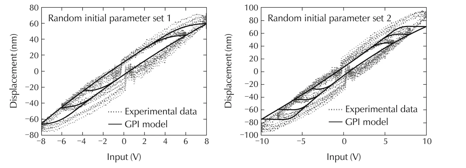
Fig.8 Modified GPI hysteresis model identified by nonlinear least square method.
(Particle swarm optimization method) As the data are captured through experiment,therefore data are usually corrupted by noise.PSO works very well with noisy data.In PSO,each potential solution of the model parameters is called a particle.Initially each particle is given a random velocity and a random position.Each particle keeps track of its own previous best position as well as the previous global best position among all the particles.It tries to modify its position by using the information of current position,current velocity,distance between the current position and previous own best position,and distance between the current position and previous global best position.
The velocity and position of each particle is changed as follows:

wherekis the iteration number;viandxiare the velocity and position of theith particle respectively;pbestiand gbest are the best position ofith particle and best position of the swarm respectively andw,c1,c2are the weight/weighing function,cognitive parameter and social parameter respectively.The PSO algorithm used in this paper is as follows:
a)Set the swarm size as tuning parameter.
b)Randomly choose the initial position and velocity randomly forˆNparticles of the swarm.The cognitive the social parameters are set as 2 and target cost function is selected as

c)Evaluate the fitness of target function for each particle.
d)Compare the personal best of each particle to its current fitness and set pbesti


f)Calculate the velocity vector and thereby update the position vector of each particle according to(12)and(13).
g)Go to step a)and change the swarm size to another numberand repeatstep b)to d).In thisway differentsets of model parameters are obtained for different swarm size from 10 to 60.
h)Similarly go to step a)and set the weight as tuning parameter and change it from 0.1 to 0.2 and set the swarm size which is obtained as the best solution in the step e).In this way different sets of model parameters are obtained for different weight values.Among these the best-fitted model parameters are chosen.
Evaluation or testingModel is identified by one set of input-output data and then evaluated by all the measured sets of input-output data.First of all,the model is identified using input-output data acquired with 6 V,100 Hz input signal and the identified model is validated using all sets of experimental input-output data.The swarm size is varied form 10 particles to 60 particles,and the corresponding the global minimum cost are compared.Then the swarm size is kept fixed and the weighting functionwis varied from 0.1 to 0.2 in order to get the best value ofw.Corresponding results are summarized in Tables5 and 6.Hysteresis plots are shown in Figs.9–12.Global minimum of the target cost function plot is shown in Fig.13.Fig.14(a)shows the experimental hysteresis response,and simulated hysteresis response obtained from identified modified GPI model.For hysteresis model identification,model responsey(0)=0 is considered for the initial inputv(0).Here in Fig.14(a),modelis identified by the training data of6 V sine input-outputresponse and evaluated by three sets of test data(6 V,8 V,and 10 V sine input-output responses).The above procedure of tuning swarm size and weights is exactly repeated to identify a modified GPI model with 10 V,100 Hz sine input-output data and again the identified GPI model is tested by using all the test input-output data(Fig.14(b)).Finally a modified GPI model is identified by segmented parameterization where the swarm size and weight are kept fixed at some optimum values.In segmented parameterization all the parameters are identified from one set(6 V,100 Hz)of input-output data and half of the parameters are picked from there.Next the rest half of the parameters are iden-tified and obtained from another set(10 V,100 Hz)of input-data(Fig.14(c)).
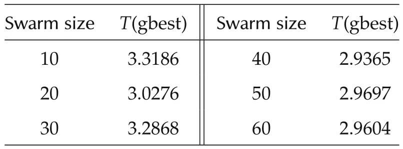
Table 5 Global minimum cost for different swarm size.
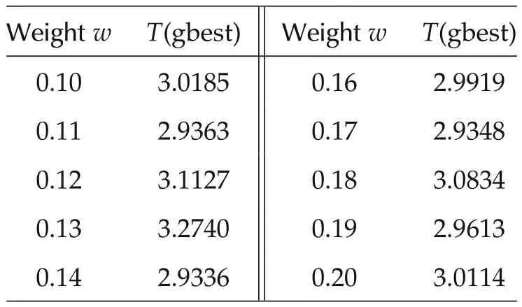
Table 6 Global minimum cost for different weights.
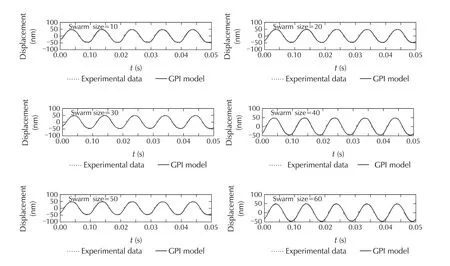
Fig.9 Measured displacements for different swarm size.
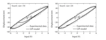
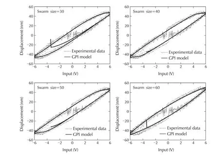
Fig.10 Hysteresis(input-output)loop for different swarm size.
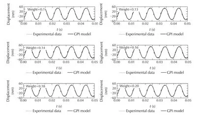
Fig.11 Measured displacements for different values of the weight.
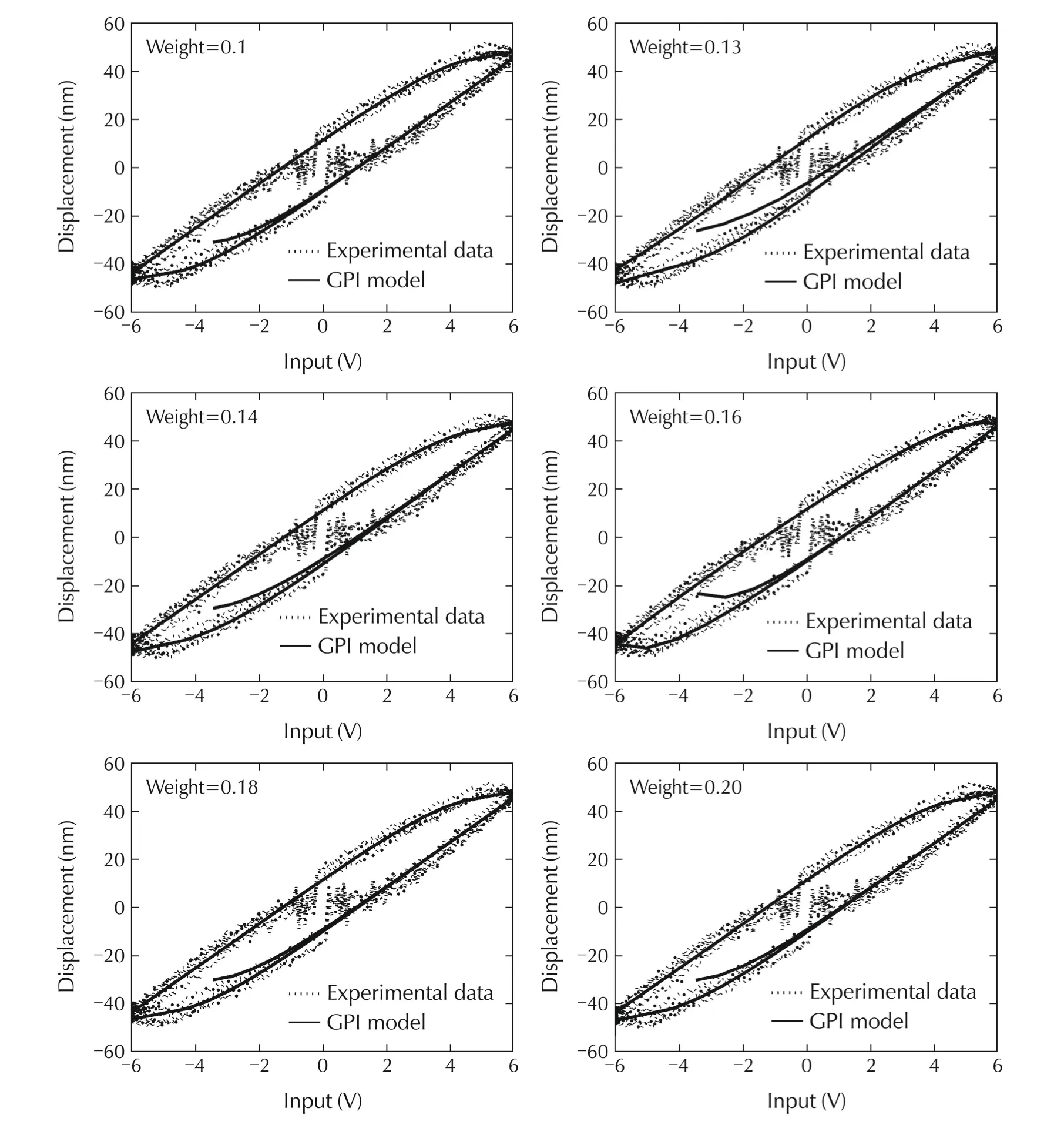
Fig.12 Hysteresis(Input-output)loop for different values of the weight.
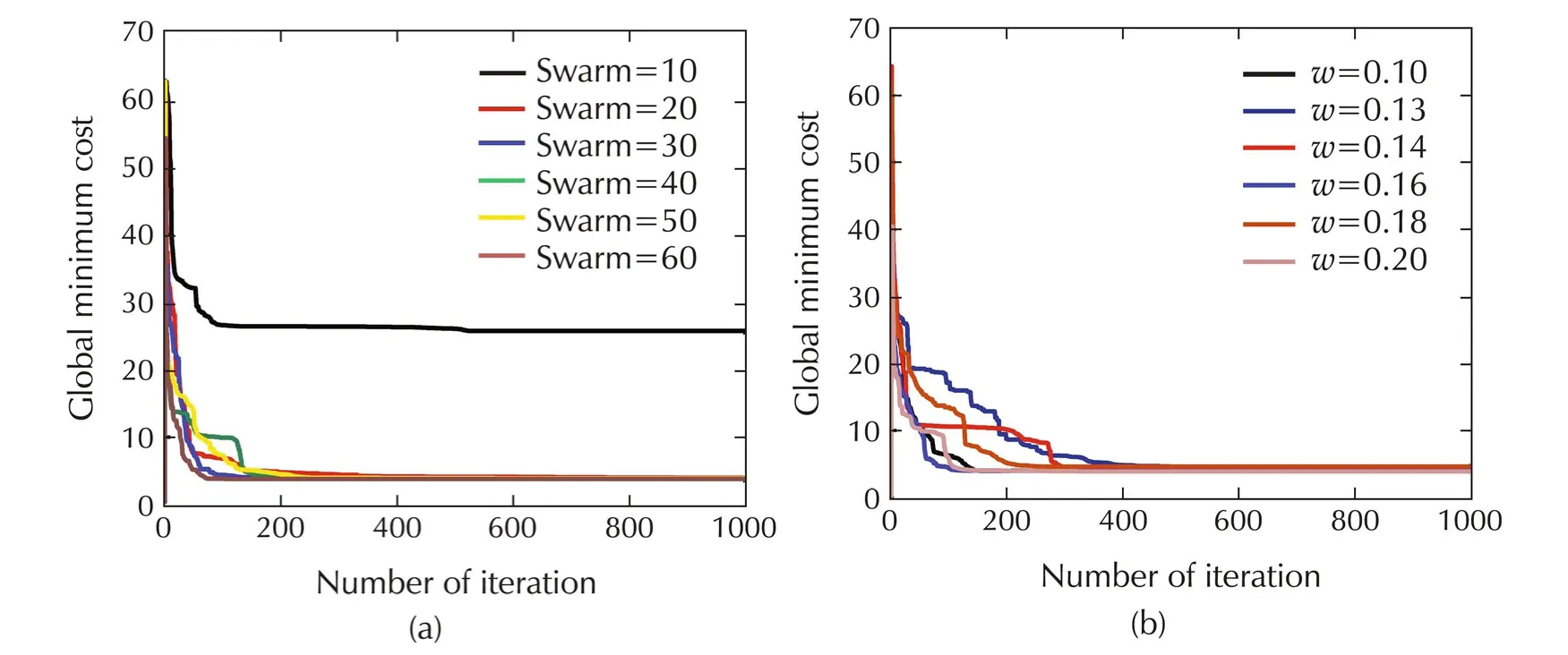
Fig.13 Global minimum of target cost function for(a)different swarm size(b)different weights.
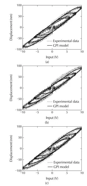
Fig.14 Hysteresis in PZT micro-actuator.(a)Modified GPI model identified by 6 V sine input-output.(b)Modified GPI model identified by 10 V sine input-output.(c)Modified GPI model identified by segmented parameterization.
3.2 Coleman-Hodgdon hysteresis model
To make a comparison between different hysteresis models,Coleman-Hodgdon model is selected.The PSO identification technique discussed in earlier section is again used to identify the Coleman-Hodgdon model.
Coleman-Hodgdon modelThe differential model of hysteresis according to[27]is a representation of dynamic effect in the form of the first order nonlinear differential equation in the time domain

This equation can be expressed in discrete form as follows:

where 0< α is a real number.It is assumed that
a)real-valued function f(·)is odd,monotone increasing and piece-wise continuously differentiable with a finite limit for its first order derivative at positive infinity.

More general forms of the functions f(·)and g(·)were considered in[e,f]for modeling ferromagnetic hysteresis.The functions f(·)and g(·)can be written as multi-segment piecewise-linear functions as follows:
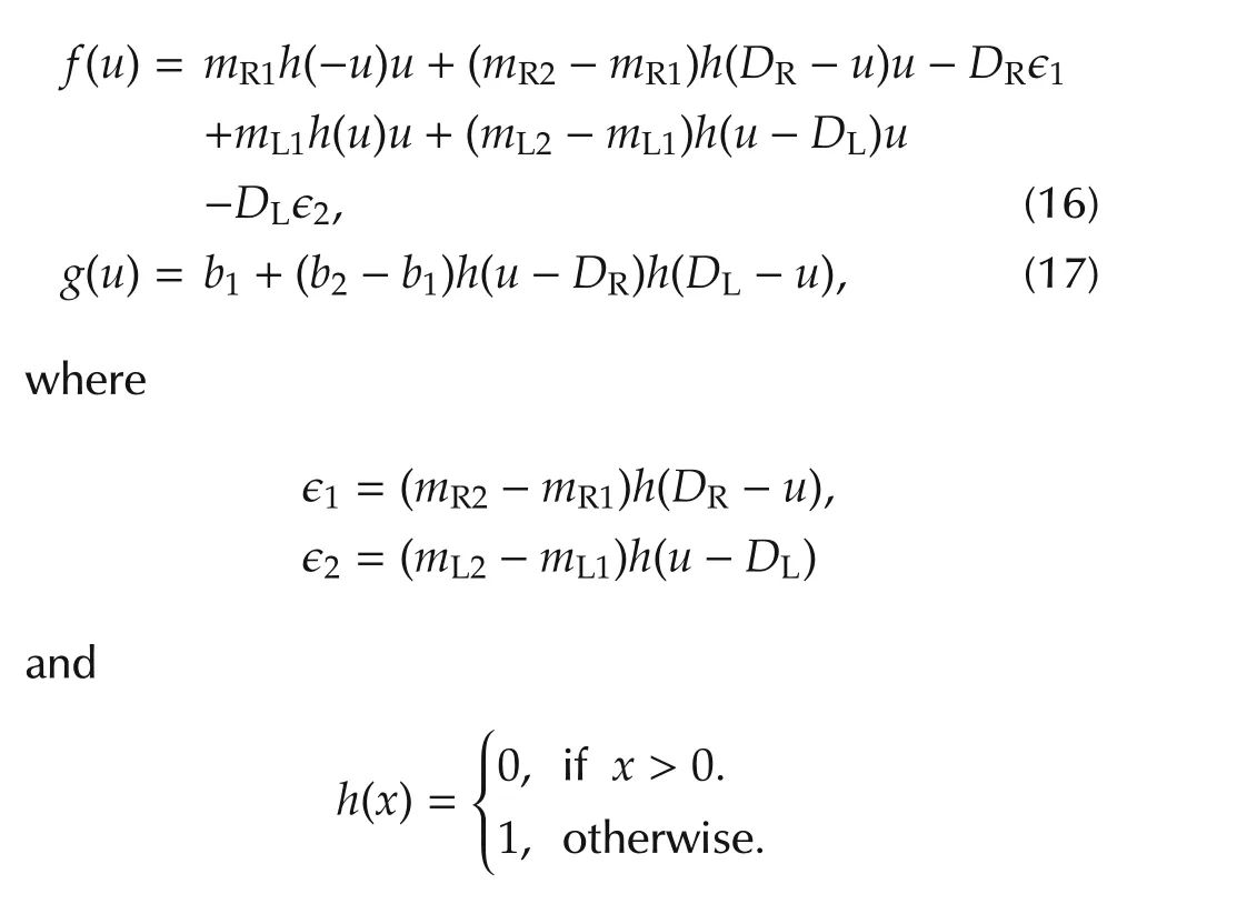
Now after subsituting f(·)and g(·)functions,
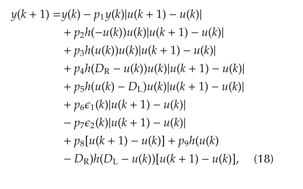
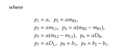
Coleman-Hodgdon model idnetified by PSOThe same identification and optimization procedure is followed as discussed in Section 3.1.The model is identified by using PSO technique.First the swarm size is tuned and the best solution is obtained.Then the weight value is tuned.From these tuning,the best optimized parameters are obtained for the model.The hysteresis input-output loops are plotted from the identified Coleman-Hodgdon model by using test input-output data(In Fig.15(a),model identified by 6 V sine inputoutput and in Fig.15(b)model identified by 10 V sine input-output).
From the identification results,it is quite clear that modified GPI model performs better than Coleman-Hodgdon model.
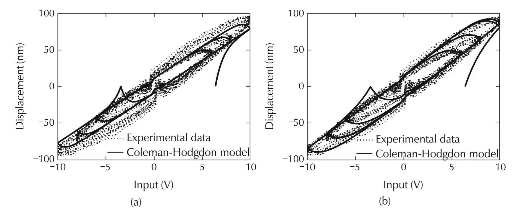
Fig.15 Hysteresis in PZT micro-actuator.(a)Coleman-Hodgdon model identified by 6 V sine input-output.(b)Coleman-Hodgdon model identified by 10 V sine input-output.
4 Nonlinear PZT model
By considering the hysteresis analysis of different hysteresis models and different identification techniques,the best fitted hysteresis model can be obtained.For the simulation purpose,the nonlinear model of PZT microactuator should be obtained.It is obtained by cascading the linear model and the hysteresis model.Note that for constructing the nonlinear PZT model,the previous analysis for hysteresis model identification is used.

whereGP(s)represents the linear model of the microactuator as in(3)andH{v}is the hysteresis model as identified in Section 3.At low frequency,˜N=KdcH{v(t)}=ˆH{v(t)}whereKdc=GP(s)|s=0is the DC gain of the linear model.Therefore,

5 Dual-stage simulation
This section presents a simulation analysis for a dualstage actuator system.The analysis is to show the effectiveness of the precise or accurate modeling.The analysis can be considered as a design example to show the importance of the perfect modeling in a dual-stage actuator system where piezoelectric micro-actuator is used as the secondary actuator.
First of all,an inverse GPI model is designed and the inverse model parameters are obtained from the previously identified modified GPI model(Section 3).This inverse GPI model works as the hysteresis compensator since it is compatible with experimental hysteresis.In the simulation analysis,nonlinearPZT model˜Nin Fig.16 is used as the micro-actuator model.

Fig.16 Nonlinear model of PZT micro-actuator.
5.1 Inverse GPI model
The parameters obtained for modified GPI model by using PSO are used for inverse GPI model.The discretetime inverse GPI model can be expressed as

where γ−1denotes the inverse function of γ and

where v(k)is the discrete time input with k=0,1,2,...,N and N being the total number of discrete samples.In(21),n is the number of generalized play operator where each operator can be described as
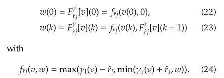
The parameters q−1,ˆrjandˆpjare obtained as
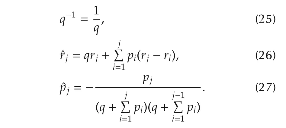
5.2 Dual-stage controller design
Feedback controller for the dual-stage hard disk drive servo system is designed,where a hysteresis compensator is included as a part of the secondary stage controller.Various methods of designing controller for dual actuated servomechanism have been reported in the literature[28–30].Commonly used configurations are parallel loop,master-slave,PQ method and decoupled master-slave(DMS)etc.In this paper,the DMS structure[31]is adopted.VCM controller is a combination of a notch filter[32]and a composite nonlinear feedback controller(CNF)[33].The CNF control consists of a linear feedback law and a nonlinear feedback law without any switching element.Both linear and nonlinear controllers in CNF are in operation all the time.The linear feedback part is designed to yield a closed-loop system with a small damping ratio for a quick response,while at the same time not exceeding the actuator limits for the desired command input levels.The nonlinear feedback law is used to increase the damping ratio of the closed-loop system as the system output approaches the target reference to reduce the overshoot caused by the linear part.Here,the CNF toolkit[34]is used to design a fast and smooth tracking controller for the VCM actuator.The toolkit views are shown in Fig.17.In this toolkit,state feedback gain matrix is selected by pole-placement method where controller structure is a reduce-order measurement feedback.A diagonal vector matrix is selected by tuning as the CNF nonlinear feedback part.
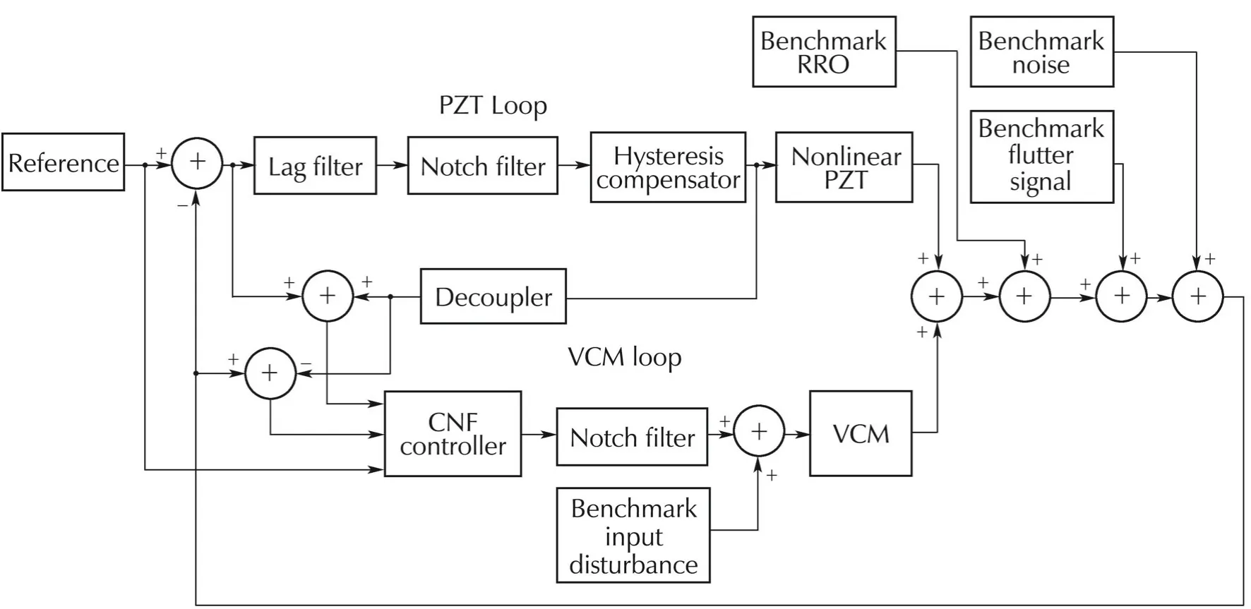
Fig.17 Toolkit for CNF controller design.
PZT controller is a combination of a notch filter[32],a lag filter[35]and an inverse GPI model.Noise and various disturbances obtained from benchmark model[19]are added into the system.These include VCM disturbance,flutter disturbance,repeatable Run-Out(RRO)and sensor noise.The block diagram of the dual-stage scheme is shown in Fig.18.The time-domain disturbance models are shown in Fig.19.

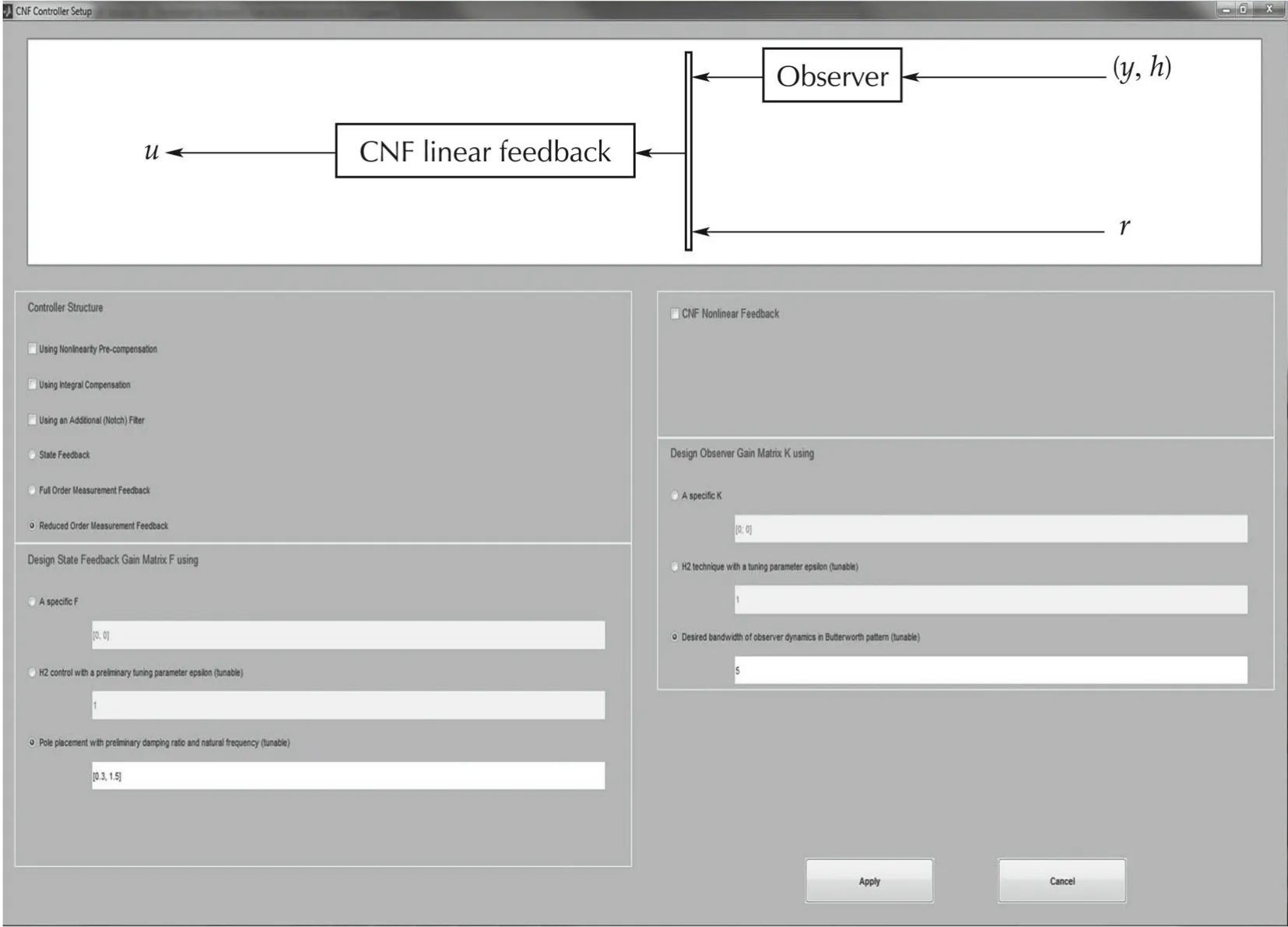
Fig.18 DMS dual-stage actuator system.

Fig.19 Benchmark disturbance and noise signals.
6 Simulation results
The system is tested in track following mode.In track following mode,the head is maintained as close as possible to the center of the track.For track following simulation,reference is set to zero and position error signals(PES)are captured.This simulates the situation when read-write head is maintained on a particular track to enable reading or writing of data.Two different scenarios are set for simulation.In both of the scenarios,same hysteresis compensator is used which is identified from the best-fitted modified GPI model parameters.
Scenario 1(Accurate modeling) In this simulation,nonlinear PZT actuator model is constructed from the combination of linear model and modified GPI hysteresis model where parameters of GPI model are identified by PSO optimized technique.This gives a model that is perfectly fitted with experimental data.The hysteresis model part is precisely matched with the hysteresis compensator model.
Scenario 2(Inaccurate modeling) In this simulation,nonlinear PZT actuator model is constructed from the combination of linear model and modified GPI hysteresis model where parameters of GPI model are identified by nonlinear least square method.This gives a model that is not exactly fitted with experimental data.The hysteresis model part is not also exactly matched with the hysteresis compensator model.
The PES and the histogram of PES are shown in Fig.20 and Fig.21 respectively for both scenario 1 and scenario 2.When the modeling is not accurate,3σ of PES is 45.14 nm where it is decreased by 50%to 22.69 nm when modeling is accurate and precise.
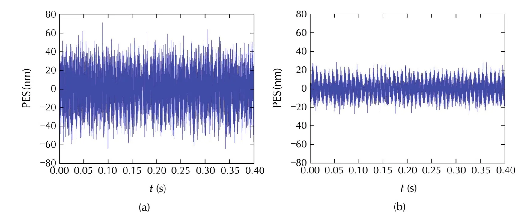
Fig.20 Position error signal(PES).
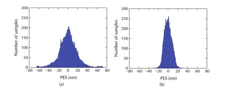
Fig.21 Histogram of PES.
7 Conclusions
This paper presents a rigorous analysis and modeling of hysteresis nonlinearity seen in PZT micro-actuator.Two types of hysteresis model are considered in the analysis and modified GPI model performs better than the other.Use of derivative-free PSO technique with different parameters tuning resulted an efficient identification of nonlinear model of the micro-actuator.Therefore,an effective compensator for hysteresis can be designed.The controllers for the coarse and fine actuators are designed independently ensuring the stability of the VCM loop subject to secondary-stage failure.Since the displacement contributed by the VCM alone cannot be measured,feedforward estimation of the displacement contributed by the micro-actuator is used to determine displacement due to the coarse actuator.The proposed scheme is shown successful to compensate for the nonlinear hysteresis of the PZT micro-actuator.The positioning accuracy of the servo system is improved in terms of reducing PES.Although this paper substantiates the application of proposed scheme to compensate forhysteresisbehaviorand improving the system performance of a dual-stage actuation system of a commercial HDD,this scheme can be applied to many other applications where hysteresis behavior is encountered or to any kind of dual-stage system where piezoelectric actuator is used.As the part of current and future research,experimental verification of this technique is on-going and we hope to report the results in future.
Acknowledgements
The authors would like to thank Professor Ben M.Chen from the Department of ECE,NUS for providing the CNF toolkit[34]and necessary supporting documents related to the toolkit.
[1]G.Tao,P.V.Kokotovic.Adaptive control of plant with unknown hysteresis.IEEE Transactions on Automatic Control,1995,40(2):200–212.
[2]Q.Xu.Identification and compensation ofpiezoelectric hysteresis without modeling hysteresis inverse.IEEE Transactions on Industrial Electronics,2013,60(9):3927–3937.
[3]A.A.Eielsen,J.T.Gravdahl,K.Y.Pettersen.Adaptive feed-forward hysteresis compensation for piezoelectric actuators.Review of Scientific Instruments,2012,83(8):DOI 10.1063/1.4739923.
[4] C.Olmi,L.Y.Li,G.B.Song,et al.A novel hysteresis reducing piezoceramic amplifier.Chinese Control and Decision Conference,New York:IEEE,2011:716–721.
[5]M.Bazghaleh,S.Grainger,B.Cazzolato,et al.Implementation and analysis ofan innovative digitalcharge amplifierforhysteresis reduction in piezoelectric stack actuators.Review of Scientific Instruments,2014,85(4):DOI 10.1063/1.4871295.
[6]R.C.Smith.Smart Material System:Model Development.Philadelphia:Society for Industrial and Applied Mathematics,2005.
[7]K.Leang,Q.Zou,S.Devasia.Feedforward control of piezoactuators in atomic force microscope systems:inversionbased compensation for dynamics and hysteresis.IEEE Control Systyem Magazine,2009,19(1):70–82.
[8]I.D.Mayergoyz.Mathematical Models of Hysteresis.New York:Elsevier,2003.
[9]M.Brokate,J.Sprekels.Hysteresis and Phase transitions.New York:Springer,1996.
[10]A.Visintin.Differential Models of Hysteresis.Berlin:Springer,1994.
[11]D.Habineza,M.Rakotondrabe,Y.Le Gorrec.Modeling,identification and feedforward control of multivariable hysteresis by combining Bouc-Wen equations and the inverse multiplicative structure.Proceedings of the American Control Conference,New York:IEEE,2014:4771–4777.
[12]A.Laudani,F.R.Fulginei,A.Salvini.Bouc-wen hysteresis model identification by the metric-topological evolutionary optimization.IEEE Transactions on Magnetics,2014,50(2):621–624.
[13]Y.Shan,J.Speich,K.Leang.Low-cost IR reflective sensors for submicrolevel position measurement and control.IEEE/ASME Transactions on Mechatronics,2008,13(6):700–709.
[14]G.Gu,L.Zhu.High-speed tracking control of piezoelectric actuators using an ellipse-based hysteresis model.Review of Scientific Instruments,2010,81(8):DOI 10.1063/1.3470117.
[15]Y.Qin,Y.Tian,D.Zhang,et al.A novel direct inverse modeling approach for hysteresis compensation of piezoelectric actuator in feedforward applications.IEEE/ASME Transactions on Mechatronics,2013,18(3):981–989.
[16]G.Yang,M.Yang,L.Zhu.Real-time inverse hysteresis compensation of piezoelectric actuators with a modified Prandtl-Ishlinskii model.Review of Scientific Instruments,2012,83(6):DOI 10.1063/1.4728575.
[17]M.Al Janaideh,J.Mao,S.Rakheja,et al.Generalized Prandtl-Ishlinskii hysteresis model:hysteresis modeling and its inverse for compensation in smart actuators.Proceedings of the 47th IEEE Conference on Decision and Control,Piscataway:IEEE,2008:5182–5188.
[18]Y.Li,R.Horowitz,R.Evans.Vibration control of a PZT actuated suspension dual-stage servo system using a PZT sensor.IEEE Transactions on Magnetics,2003,39(2):932–937.
[19]M.A.Rahman,A.A.Mamun,K.Yao,et al.Particle swarm optimization based modeling and compensation of hysteresis of PZT micro-actuator used in high precision dual-stage servo system.IEEE International Conference on Mechatronics and Automation,Piscataway:IEEE,2014:452–457.
[20]M.A.Rahman,A.Al Mamun.Nonlinearity analysis,modeling and compensation in PZT micro-actuator of dual-stage actuator system.Proceedings of the 11th IEEE International Conference on Control and Automation,New York:IEEE,2014:1275–1280.
[21]C.Maurice.Particle Swarm Optimization.London:Wiley,2006.
[22]J.R.Chen,P.Mars.The feasibility of using MLP neural networks for system identification.IEE Colloquium on Neural Networks for systems:Principles and Applications,London:IEE,1991:1–3.
[23]M.S.White,S.J.Flockton.Evolutionary Algorithms in Engineering Application.Berlin:Springer,1997.
[24]T.Kumon,M.Iwasaki,T.Suzuki,et al.Nonlinear system identification using genetic algorithm.Proceedings of the IEEE International Conference on Industrial Electronics,Control and Instrumentation,Piscataway:IEEE,2000:2485–2491.
[25]K.F.Man,K.S.Tang,S.Kwong.Genetic algorithms:concepts and application.IEEE Transactions on Industrial Electronics,1996,43(5):519–534.
[26]G.Venter,J.S.Sobieski.Particle swarm optimization.AIAA Journal,2003,41(8):1583–1589.
[27]J.Voros.Modeling and identification of hysteresis using special forms of the coleman-hodgdon model.Journal of Electrical Engineering,2009,60(2):100–105.
[28]G.Guo,Q.Hao,T.S.Low.A dual-stage control design for high track per inch hard disk drives.IEEE Transactions on Magnetics,2001,37(2):860–865.
[29]L.S.Fan,H.H.Ottesen,T.C.Reiley,et al.Magnetic recording head positioning at very high track densities using a microactuator-based two-stage servo system.IEEE Transactions on Industrial Electronics,1995,42(3):222–233.
[30]M.Karaman,W.C.Messner.Robust dual stage HDD track follow control systems design for hand-off shaping.Digest of the Asia-Pacific Magnetic Recording Conference,Singapore:IEEE,2002:DOI 10.1109/APMRC.2002.1037636.
[31]L.Guo,D.Martin,D.Brunnett.Dual-stage actuator servo control for high density disk drives.IEEE/ASME International Conference on Advanced Intelligent Mechatronics,Piscataway:IEEE,1999:132–137.
[32]D.Wu,G.Guo,T.C.Chong.Comparative analysis on resonance compensation in HDD dual-stage actuation systems.IEEE Transactions on Industrial Electronics,2003,50(6):1179–1186.
[33]B.M.Chen,T.H.Lee,K.Peng,et al.Composite nonlinear feedback control:theory and an application.IEEE Transactions on Automatic Control,2003,48(3):427–439.
[34]G.Cheng,B.M.Chen,K.Peng,et al.A Matlab toolkit for composite nonlinear feedback control.Proceedings of the 8th International Conference on Control,Automation and Robot Vision,Piscataway:IEEE,2004:878–883.
[35]A.Al-Mamun,G.Guo,C.Bi.Hard Disk Drive:Mechatronics and Control.London:CRC Press,2007.

his BSc degree in Electrical and Electronic Engineering from Bangladesh University of Engineering and Technology,Dhaka,Bangladesh in October 2009.Currently he is working toward the Ph.D.degree at the department of Electrical and Computer Engineering,National University of Singapore,Singapore.He is attached with the Mechatronics and Automation Lab.His current research includes the design and control of high precision servo system with the application to hard disk drive.His areas of focus are resonance compensation and hysteresis control of high precision servo systems.E-mail:a0092557@u.nus.edu.

Abdullah Al MAMUNis currently an Associate Professor in the Department of Electrical and Computer Engineering,National University of Singapore.He graduated from I.I.T.Kharagpur,India in 1985 and obtained Ph.D.from National University of Singapore in 1997.He has published 50 journalpapers and about60 papers in conference proceedings;he has co-authored one book.His research interests are in the areas of precision servomechanism,intelligent control and mobile robots.E-mail:eleaam@nus.edu.sg.

Kui YAOreceived his bachelor degree in E.E.and Ph.Din electronic materials and devices,both from Xi’an Jiaotong University,China,in 1989 and 1995,respectively,and his master degree in technical physics from Xidian University,China,in 1992.Currently,he is a principal scientist,and the manager of Sensor and Transducer Program,in Institute of Materials Research and Engineering(IMRE),A*STAR,Singapore.During 1998-1999,he worked in the Materials Research Laboratory,The Pennsylvania State University,USA.Previously,he was a postdoctoral research fellow in the Microelectronics Center at Nanyang Technological University(NTU),Singapore,during 1995-1997.His research interests cover smart materials with signal and energy conversion and storage functions,including ferroic,piezoelectric,photovoltaic,and biochemical sensing materials,material-critical sensors,actuators,transducers,and their applications.E-mail:k-yao@imre.a-star.edu.sg.
†Corresponding author.
E-mail:a0092557@u.nus.edu.Tel.:+65 8151-6389.
This work was supported by the Singapore NationalResearch Foundation(NRF)underCRP Award(Nos.NRF-CRP-4-2008-06,IMRE/10-1C0107).
©2015 South China University of Technology,Academy of Mathematics and Systems Science,CAS,and Springer-Verlag Berlin Heidelberg
杂志排行
Control Theory and Technology的其它文章
- Distributed dynamic pricing based on demand-supply balance and voltage phase difference in power grid
- Decentralized load frequency control for two-area interconnected power system
- Increasing the operating area of shunt active filters by advanced nonlinear control
- Simple adaptive air-fuel ratio control of a port injection SI engine with a cylinder pressure sensor
- Estimation and feedback control of air-fuel ratio for gasoline engines
- Gain-scheduling control of a floating offshore wind turbine above rated wind speed
