Hardware-implementable vector tracking loop for GNSS/INS deep integration
2015-06-05LIUGangGUOMeifengZHANGRongCUIXiaoweiLIShunzhong
LIU Gang, GUO Mei-feng, ZHANG Rong, CUI Xiao-wei, LI Shun-zhong
(1. Department of Precision Instrument, Tsinghua University, Beijing 100084, China; 2. Department of Control Engineering, Naval Aeronautical and Astronautical University, Yantai 264001, China; 3. Department of Electronic Engineering, Tsinghua University, Beijing 100084, China;
Hardware-implementable vector tracking loop for GNSS/INS deep integration
LIU Gang1,2, GUO Mei-feng1, ZHANG Rong1, CUI Xiao-wei3, LI Shun-zhong1
(1. Department of Precision Instrument, Tsinghua University, Beijing 100084, China; 2. Department of Control Engineering, Naval Aeronautical and Astronautical University, Yantai 264001, China; 3. Department of Electronic Engineering, Tsinghua University, Beijing 100084, China;
Tracking sensitivity and positioning accuracy of GNSS vector tracking loop (VTL) are superior to that of scalar tracking loop (STL), but VTL is difficult to implement on hardware because of three obstacles: 1) all tracking channels’ measurements and parameters must be processed at the same time for multi-channel joint tracking; 2) the processor has high computational burden due to too frequent satellite position calculation; 3) it is unable to demodulate navigation message due to non-PLL tracking mode. Thus commercial receiver usually use such STL as its hardware is easy to access and its performance is sub-optimal. To apply the VTL on an embedded hardware platform in real-time mode, three methods are introduced: 1) linear interpolation for synchronizing asynchronous-observables; 2) algorithm optimization for calculating satellite position; 3) a novel method for demodulating navigation date bits from vector frequency lock loop. Simulations of the VTL and VDI are carried out using a normal aircraft trajectory, in which data samples are generated by trajectory generator and GNSS signal simulator, and then processed and compared on Matlab platform. The results show that the calculation efficiency of satellite position has improved 55 times, and the navigation message is successfully demodulated, and the VTL’s position and velocity accuracies are better than 3 m and 0.3 m/s, respectively, while the VDI’s position and velocity accuracies are better than 2 m and 0.1 m/s, respectively.
GNSS; INS; deeply-integrated; vector tracking loop; hardware implementation
The global navigation satellite system (GNSS) has rapidly developed recent years. The availability of GNSS under challenging environments, such as low signal-tonoise ratio (SNR), high-dynamic, and multipath, has become a hot research area. In case GNSS receiver can’t work alone due to ultra-low SNR and high dynamic, INS-aiding is the best way to continue the navigation.
The complementation between GNSS and INS pushes the development of GNSS/INS integrated navigation system for several decades. Deep integration (DI) became the cutting edge of this area recently. In a DI system, INS navigation results are fed back to the GNSS tracking loop to remove dynamic effect and refine navigation results. There are two types of DI, scalar deeply integrated (SDI) and vector deeply integrated (VDI), which are sorted by GNSS tracking loop structure[1,2,10].
The VDI is based on the GNSS vector tracking loop (VTL) structure, which tracks all the satellite signals simultaneously in a single filter. Compared with the scalar tracking loop (STL) which tracks one satellite signal in one channel separately, the VTL structure has the following advantages: firstly, the geometric relationship between the receiver and different satellites is used to refine the positioning accuracy; secondly, the tracking of low SNR satellites are assisted by the tracking results of high SNR satellites; finally, the navigation results are fed back to assist signal tracking which improves the accuracy under high dynamic and low SNR environments.
Several VTL implementation architectures have been published[3-7]. Lashley stated the structure of VTL and tested VTL’s performance improvement compared to STL under high dynamics and low SNR[3]. Zhao Sihao realized VTL on a Matlab-based platform[4-5]. Lin Tao demonstrated a method of VTL in navigation domain which uses position and velocity of receiver to track satellite signal[6]. Liu Jing proposed a VTL using maximum likelihood (ML) estimation method[7]. But all of the VTLs mentioned above have the following disadvantages: firstly, they are implemented on a software-based receiver with data bit wipe-off technology in which navigation bits must be downloaded before, and this is not suitable for real-time embedded realization; secondly, VTL uses FLL-like loop to track carrier frequency which means it is impossible to demodulate navigation data directly; finally, more than 50 times per second of calculation of satellite position and velocity is a burden for real time hardware implementation. As a result, the VTL is not suitable for hardware implementation.
This paper implements a VTL suitable for hardware implementation based on the VTL structure, and GNSS/ INS VDI algorithm can be realized on a real time hardware platform. The VTL contains a vector delay-lockloop (VDLL) and a vector frequency-lock-loop (VFLL). the VTL has several differences compared with the former implementations. The first difference is that it utilizes a linear interpolation method to synchronize the Kalman observables when using asynchronous correlators synchronized with navigation data bit edge. The second improvement is that an algorithm of demodulating navigation data messages has been introduced to extract navigation bits from VFLL. The third modification is that it utilizes the seventh-orderpiecewise-Hermite interpolation method to optimize the calculation of satellite position and velocity.
The rest of paper is organized as follows. A mathmatic model of received GNSS signal is presented in section 1. Section 2 introduces the VDL structure and flow chart, including the modifications. Section 3 states the schedule and details of the simulation experiments. VDL simulation results, VDI simulation results and their comparison are proposed in section 4. Finally, the conclusion and future work are showed in section 5.
1 Signal model
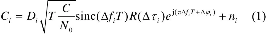
Where Diis the data bits, Tis the correlation interval, C/N0is the carrier power to noise power spectral density, Δfi=fcarr,i-arr,iis the frequency estimation error, Δτi=τi-is the code delay estimation error, Δφi=φi-is the initial phase estimation error, R(·) is the code correlation function, and niis the complex white Gaussian noise sequence with unit variance.
Using different delay of local replica Pseudorandom code, equation (1) gives EI (Early I) component correlation IE, EI (Early Q) component correlation QE, and also IP, QP, IL, QL, with which the Kalman observables could be generated.

2 Vector tracking loop specifications
Fig.1 shows the structure of the VTL.
The VTL is mostly consisted of local signal generator, signal tracking error discriminator and extended Kalman filter (EKF). The local signal generator includes three modules: position/velocity prediction module, code phase/frequency computation module and code/carrier generation module.
Fig.2 shows the flow chart of the VTL.
The VTL works as follows: the predicted receiver position and velocity are used to calculate the code phase/ frequency and carrier frequency which are required for generating local replica signal. The local replica signal is correlated with the incoming satellite signal, and then is accumulated to generate the IE, IP, IL, QE, QPand QLcorrelations with 20 ms period. The discriminator handles the correlations to generate the observables of code phase error and carrier frequency error. After processing by EKF, the estimated position/velocity errors and clock errors are used to correct the VTL parameters. Then comes the next loop.

Fig.1 Structure of the vector tracking loop

Fig.2 Flow chart of the vector tracking loop
A more detailed description is proposed as follows:
Suppose the kth epoch parameters are known, which are ephemeris, code frequency fcode,i, code phase τi, carrier frequency fcarr,i, signal transmit time tt,i, receiver clock bias tbwith unit of m, clock drift tdwith unit of m/s, receiver ECEF position p=(xu,yu,zu), receiver ECEF velocity v=(vx,vy,vz), where i stands for the ith satellite. Then the k+1th epoch parameters can be predicted as:

Where tk,k+1is the interval from k to k+1 epoch.Satellite position and velocity are calculated from the ephemeris, and then the k+1th epoch baseband control parameters can be derived as:

Where Δpi,k,k+1is the ith satellite’s movement vector within tk,k+1, vi,kis the ith satellite’s velocity, ui,k+1=(uix,uiy,uiz)is the line-of-sight unit vector pointing from the receiver to the ith satellite, fcode= 1.023 MHz is the standard code frequency, fcarris the standard carrier frequency, and Δtbis the clock bias error.
Baseband control parameters are used to generate local replica signals which are correlated with the incoming satellite signals to generate IE, QE, IP, QP, IL and QL.
This paper chooses EKF to handle the tracking and navigation tasks. The state vector of the EKF includes receiver’s three-dimensional position error, three-dimensional velocity error, clock bias error, and clock drift error.

The discrete transition function of the EKF is:

All the available satellites’ outputs of code phase discriminator and carrier frequency discriminator are used as the EKF observables.

Where zcode,iis the code phase discriminator’s output of the ith satellite, zcarr,iis the corresponding carrier frequency discriminator’s output, and N is the number of the available satellites.
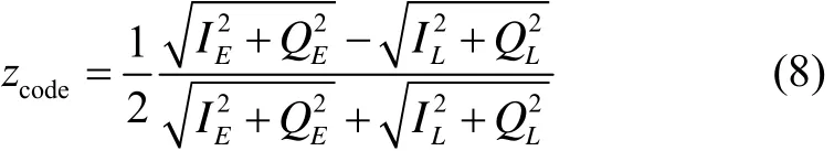
The DLL discriminator in this paper is normalized as non-coherent early minus late envelope discriminator[1]:
The FLL discriminator in this paper is[1]:

Where t1and t2are the adjacent correlation intervals.
The observation function of EKF is:

After EKF filtering, the navigation errors are updated. Then the state vector is set to zero and the algorithm comes to the next cycle.
2.1 Synchronizing method: Linear interpolation
Since different satellite signals experience different propagation delays, the bit edges of different satellite are asynchronous[8]. But the baseband correlation ends are synchronous with the bit edges, so the correlation observables are asynchronous, as shown in Fig.3.

Fig.3 Example of asynchronous correlation and linear interpolation method
In the EKF, observables must be obtained simultaneously, so linear interpolation is used to synchronize the asynchronous correlation results. At observing epoch tk, the ith satellite observables is :

For GNSS/INS deeply-integrated application, the observing epoch could be synchronized with the INS sampling epoch.
2.2 Algorithm of decoding navigation data
When using a VFLL to track the carrier frequency, the signal power is distributed over I channel and Q channel, so navigation bits can’t be fetched directly.
This paper uses dot-multiply of the adjacent two conjugate complex prompt correlations to extract the navigation bits[2]. This can be derived as:

This function supposes that the delta carrier frequency between the two adjacent correlation intervals is less than 1/(4T), which ensures that[is positive, so when navigation bit change occurs, the dot-multiply is negative, otherwise, it is positive.
The performance of data demodulation is measured in terms of bit error rate (BER). for VFLL:

Where S/N0is the signal to noise ratio[2].
The algorithm is utilized to demodulate a 10 s long GPS signal with highS/N0, and the BER is zero. A part of the demodulated data is demonstrated in Fig.4.
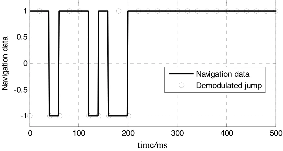
Fig.4 Demodulation results of navigation data
2.3 Satellite orbit interpolation algorithm
Edwards and Lashley[9]has realized a real-time VTL using field-programmable-gate-arrays (FPGA) with a fast microprocessor. In this implementation, the correlation interval is 20 ms, which means that the microprocessor must finish all of the calculation task within 20 ms. Edwards’ algorithm loop costs 15.5722 ms, among which 7.9164 ms was occupied by computing satellite position and velocity. So the calculation of satellite position and velocity is the major part that needs to be optimized to accommodate other application, e.g. the GNSS and INS integration. It suggests that we can use piecewise-Hermite interpolation to optimize the calculation of satellite position and velocity. Reference [11] proved that the most efficient method in terms of low computational cost, easy implementation and sufficient precision of less than 10 cm and 1 mm/s is piecewise-cubic-Hermite interpolation with sampling intervals of about 100-200 s[12].
This paper uses a 7th-order piecewise-Hermite interpolation with sampling intervals of 100 s. The integration time of tracking loop is 20 ms, so 50 calculations of satellite position/velocity are carried out per second.
To verify the efficient and accuracy of the Hermite interpolation algorithm, 10 000 s satellite orbit calculation are performed on the Matlab-based platform with Intel i5 CPU. The non-interpolatory method costs 233.6798 s, while the Hermite interpolation algorithm costs 4.2567 s, showing 55 times faster than the conventional method.
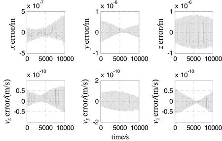
Fig.5 Interpolation errors
Fig.5 shows the interpolation errors, in which the interpolation standard deviation of position and velocity are 5.64×10⁻⁷m and 6.77×10⁻¹¹m/s, respectively, which could be ignored for VTL application.
3 Schedule and details of the simulation experiments
This paper designs two types of simulation experiments, one is the VTL simulation based on the structure introduced in section 2, the other is VDI simulation which involves INS aiding.
Design an airplane’s coordinated turn trajectory, in which the airplane velocity is 200 m/s, and the roll angle is less than 30°. The trajectory of the airplane is shown in Fig.6.
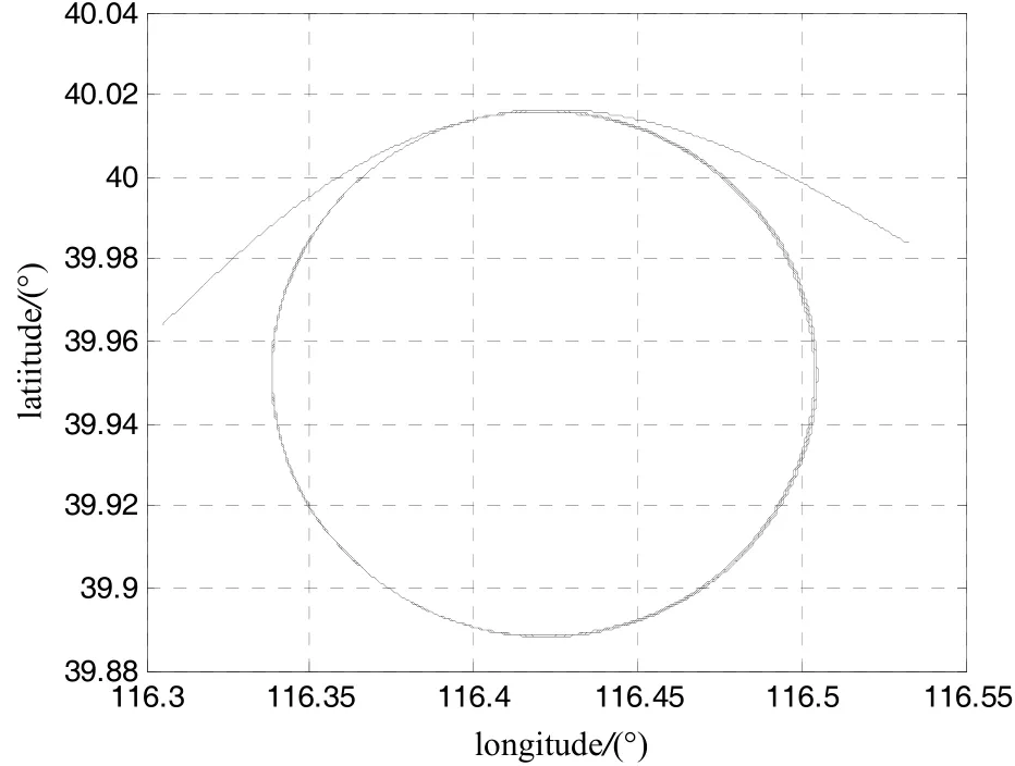
Fig.6 Coordinated turn trajectory of the airplane
GNSS intermediate-frequency simulator generates the satellite signal according to the trajectory. Characteristics of the INS and satellite signal are listed in Tab.1.

Tab.1 Characteristics of the INS and GNSS
Fig.7 shows the structure of the VDI. The INS position and velocity are used to predict the code phase/ frequency and carrier frequency which are required for generating local replica signal. The local replica signal is correlated with the incoming satellite signal, and then is accumulated to generate the IE, IP, IL, QE, QP and QL correlations with 20 ms period. The discriminator handles the correlations to generate the observables of code phase error and carrier frequency error. After processing by EKF, the estimated INS errors and clock errors are used to correct the VDI parameters.
The VDI uses 17th-dimensional state vector: threedimensional attitude, velocity, and position, gyroscope bias, accelerator bias and clock bias, clock drift. Otherwise, the implementation of EKF is the same as that of VTL.
4 Simulation results
The VTL and VDI algorithms are simulated on a Matlab-based platform according to the structure in Fig.1 and Fig.7. Real-time navigation bits are decoded. Simulation results show that the two methods can track satellite signal well. By comparing with the original trajectory, the navigation errors are shown in Fig.8.
Tab.2 shows the standard deviations of the navigation solution errors which indicate that the VDI provides more accurate navigation solutions than the VTL, in particular, the velocity has improved an order of magnitude. However, the standard deviation of errors will increase as the SNRs of satellite signals decrease.
On the other hand, the INS aiding enhances the dynamic performance of GNSS receiver when receiver encounters signal outage. INS can help maintain tracking satellite signals for a short time. If signal outrage disappears within this time, none re-acquisition is needed.
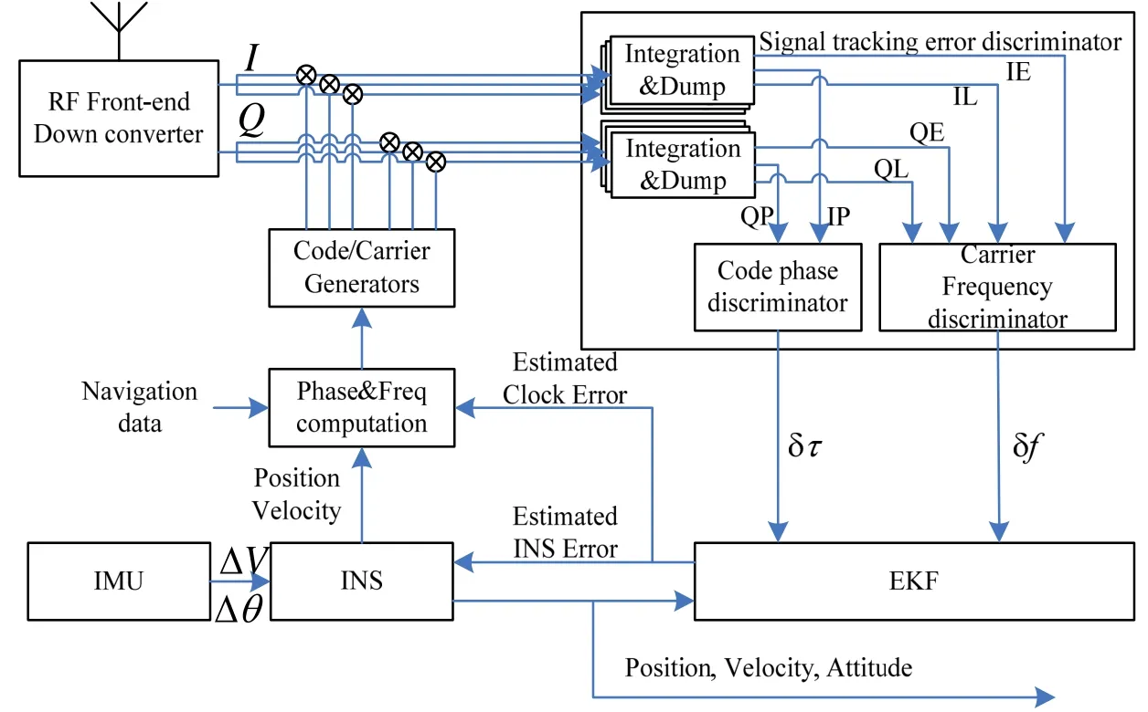
Fig.7 Structure of the vector deeply-integrated algorithm
5 Conclusion and future work
This paper proposes a method of vector tracking loop for hardware implementation in real-time without navigation-bit wiping-off technology, based on which GNSS/INS VDI algorithm could be realized. To ensure the embedded hardware implementation in real-time, this paper presents an algorithm to extract navigation bits from vector frequency lock loop; on the other hand, linear interpolation is used to form the synchronous observables for the extended Kalman filter; finally, Hermite interpolation is used to rapidly calculate satellite’s position and velocity.
Vector deeply-integrated algorithm is demonstrated based on the VTL, which is helpful for improving the navigation accuracy.
Two types of simulation experiments are carried out on a Matlab-based platform to evaluate the function and accuracy of the VTL and VDI. Simulationresults show that the VTL and VDI can work correctly. Under the circumstance of airplane coordinated turn trajectory described in section 3, the position error standard deviations of the VTL and VDI are 2.4224 m and 1.3528 m, respectively, their velocity error standard deviations are 0.2386 m/s and 0.0135 m/s, respectively, and the attitude error standard deviation of VDI is 0.0103°. Thus, compared with the VTL, the VDI demonstrates more accurate navigation results under the INS-aiding.

Fig.8 Navigation errors comparison between VTL and VDI

Tab.2 Standard deviations of navigation errors
The algorithm realized on the Matlab-based platform is easy to be applied on a hardware platform, which will be carried out in the near future.
[1] Kaplan E D, Hegarty C. Under GPS: principles and applications[M]. 2nd ed. Artech House Inc, MA, 2006: 153-242.
[2] Parkinson B W, Spilker J J. Global positioning system: Theory and applications[M]. American Institute of Aeronautics and Astronautics, Washington DC, 1996.
[3] Lashley M. Modeling and performance analysis of GPS vector tracking algorithms[D]. PhD Dissertation, Auburn University, Alabama, 2009.
[4] Zhao S, Akos D. An open source GPS/GNSS vector tracking loop-implementation, filter tuning, and results[C] //Proceedings of Institute of Navigation International Technical Meeting. San Diego, CA, 2011: 1293-1305.
[5] Zhao S, Lu M Q, Feng Z M. Implementation and performance assessment of a vector tracking method based on a software GPS receiver[J]. The Journal of Navigation, 2011, 64: 151-161.
[6] Lin T, Curran J T, O’Driscoll C. Implementation of a navigation domain GNSS signal tracking loop[C]// Proceedings of Institute of Navigation International GNSS. Portland, USA, 2011: 3644-3651.
[7] Liu J, Cui X W, Lu M Q. A vector tracking loop based on ML estimation in dynamic week signal environments[C]// CSNC2012. Guangzhou, China, 2012: 629-643.
[8] Pedro A R, Javier G G, Carlos H M. Data-bits asynchronous tracking loop scheme for high performance real-time GNSS receivers[C]//The Fourth International Conference on Advances in Satellite and Space Communications. Venice, Italy, 2012: 108-113.
[9] Edwards W L, Lashley M. Bevly D M. FPGA implementation of a vector tracking GPS receiver using modelbased tools[C]//22nd International Meeting of the Satellite Division of The ION. Savannah, GA, 2009: 273-280.
[10] Petovello M G, Lachapelle G. Comparison of vector-based software receiver implementations with application to ultra-tight GPS/INS integration[C]//Proceedings of Institute of Navigation International GNSS. Fort Worth TX, USA, 2006: 1790-1799.
[11] Korvenoja P, Piche R. Efficient satellite orbit approximation [C]//Proceedings of Institute of Navigation International GNSS. Salt Lake City, USA, 2000: 1930-1937.
硬件可实现的GNSS/INS矢量深组合跟踪环路
刘 刚1,2,郭美凤1,张 嵘1,崔晓伟3,李顺忠1
(1. 清华大学 精密仪器系,北京 100084;2. 海军航空工程学院 控制工程系,烟台 264001;3. 清华大学 电子工程系,北京 100084)
GNSS矢量跟踪环路(VTL)跟踪灵敏度和定位精度优于标量跟踪环路(STL),但实现复杂度高,三个主要难点是:多通道联合跟踪要求各通道同时获取观测量并在同一时刻更新环路参数;高频率计算卫星位置加重处理器运算负担;无法跟踪载波相位导致无法解调导航电文。以上三个难点阻碍VTL在硬件平台上实现,因此商业接收机通常使用容易硬件实现的STL,但性能次优。为了在嵌入式硬件平台上实现VTL,引入三种方法:异步观测量线性插值、卫星位置计算算法优化、特殊的导航电文解调方法,之后通过仿真验证优化算法的功能及性能。使用航迹发生器生成飞机协调转弯航迹,再使用GNSS卫星信号模拟器产生中频采样信号,基于Matlab平台处理数据并进行了对比分析。仿真结果表明该VTL计算卫星位置效率提升55倍,成功解调导航电文,VTL位置精度优于3 m,速度精度优于0.3 m/s,基于该VTL的矢量深组合(VDI)算法位置精度优于2 m,速度精度优于0.1 m/s。
全球导航卫星系统;惯性导航系统;深组合;矢量跟踪环路;硬件实现
U666.1
A
1005-6734(2015)02-0189-07
2014-10-22;
2012-01-20
总装十二五预研(20114113019)
刘刚(1985—),男,博士研究生,从事组合导航研究。E-mail:gang-liu07@mails.tsinghua.edu.cn
ved GNSS signal is down-converted, sampled, demodulated and correlated. The complex correlations of ithsatellite can be expressed as[1]:
10.13695/j.cnki.12-1222/o3.2015.02.010
联 系 人:张嵘(1968—),男,研究员,博士生导师。E-mail:rongzh@mail.tsinghua.edu.cn