异形复层结构TiO2纳米棒薄膜的水热合成及性能
2013-09-15秦海洋李林峰贾春阳万中全曾宪光
庄 稼 秦海洋*, 李林峰 周 莹 贾春阳 万中全 曾宪光,3
(1西南石油大学材料科学与工程学院,成都 610500)
(2电子科技大学电子薄膜与集成器件国家重点实验室,成都 610054)
(3材料腐蚀与防护四川省重点实验室,自贡 643000)
The preparation of semi-conductor TiO2used as the anode material to adsorb dye of dye-sensitized solar cells(DSSC)which was a novel photovoltaic devices and reported first by Grätzel has been widely investigated since 1991[1].At present,many different morphological TiO2films have been studied,as reported in[2-8],such as TiO2multiporous films,TiO2nanorod arrays,TiO2nanotubes,TiO2microspheres and TiO2hollow spheres.In addition,different preparation methods of TiO2films[9-13], such as hydrothermal synthesis, template method, selfassembly method,electrophoresis deposition method,electrochemical deposition method,anodic oxidation method and vapor deposition method have been proposed.Also modifications of different morphological TiO2werereported in[14-19].Aswell known,TiO2nanorods or nanotubes offer direct electrical pathways for photogenerated electrons and could increase the electron transport rate[20-21],which could improve and enhance the conversion efficiency of DSSC.At the moment,hydrothermal synthesis and anodic oxidation method were the main methods of preparing onedimensional TiO2nanorods or nanotubes.Hydrothermal synthesis was a low cost and simple method,but the TiO2nanorods film prepared with hydrothermal synthesis was generally very thin and has many defects.On the other hand,anodic oxidation method which was a complex and high cost method was usually used to prepare thick TiO2nanotubes films.
In this work,a type of novel and thick TiO2array-cluster film was prepared by hydrothermal method.Moreover,the TiO2array-cluster film has twolayer structure.The subjacent layer was TiO2array,while the supernatant layer was TiO2clusters.Both of them were formed from TiO2nanorods and this twolayer structure of TiO2film favored to adsorb more dye,which had potential for improving the light-toelectricity conversion efciency of DSSC.
1 Experimental
1.1 Materials and preparation
All chemicals were of analytical grade and used without further purification.
In a typical procedure,the deionized water was mixed with hydrochloric acid (36.5%by weight)with volume ratios of 1∶1,in a beaker(100 mL volume).In the next step,the mixture was stirred by magnetic stirring apparatus for 10 min at ambient conditions after the addition of a specified volume of tetrabutyl titanate (TBOT,by weight).Then,the mixture was transferred into a Teon-lined stainless steel autoclave with a capacity of 50 mL.A piece of FTO substrate(F:SnO2)was ultrasonically cleaned for 60 min in a mixed solution of deionized water and acetone with volume ratios of 1∶1,were placed at an angle against the wall of the Teon-liner.The autoclave was maintained at 140 ℃ for 12~72 h in an electric oven,and subsequently cooled to room temperature under owing water,which took about 10 min.Finally,the FTO substrate was taken out,rinsed with deionized water and dried at ambient conditions.
1.2 DSSC fabrication
The DSSC were fabricated by the TiO2arraycluster films photo-anode obtained in 1.1,electrolyte of I-/I3-,and platinum (Pt)counter electrode.Furthermore,the TiO2array-cluster films photo-anode were immersed in the 0.3 mmol·L-1ethanolic solution of N-719 for 24 h.
1.3 Characterization
The crystal structure of the TiO2array-cluster films were examined by X-ray diffraction (XRD).The XRD patterns were recorded in an X-ray diffractometer(X′pertPRO,PANalytical)with Cu Kα radiation(λ=0.154 06 nm)at a scanning speed of 2°·min-1operated at 40 kV and 40 mA.The morphology of the films were examined by eld emission scanning electron microscopy(FESEM,JSM-7500F,JEOL).The current-voltage characteristics were recorded with an electrochemical workstation under a simulated solar spectrum (AM1.5)produced by a solar simulator(CEL-S500,Beijing of China).
2 Results and discussion
2.1 XRD Patterns of the films

As shown in Fig.1,that XRD patterns have no the diffraction peaks of TiO2on SnO2/FTO in Fig.1(a),only presenting the diffraction peaks of SnO2conducting film.All the diffraction peaks of array films in Fig.1(b)and array-cluster films in Fig.1(c)agree well with the TiO2tetragonal rutile phase,indicating the films prepared on FTO substrates were rutile TiO2.Compared to the rutile TiO2standard PDF card,the (002)diffraction peak of Fig.1(b)was significantly enhanced,and some diffraction peaks including (111)and (211)were absent,which indicates that the TiO2array film was highly oriented with respect to the substrate surface and the TiO2array film grew in the [001]direction with the growth axis parallel to the substrate surface normal[20].In comparison with the XRD patterns of TiO2array film,the (002)diffraction peak of Fig.1(c)became weakened,which indicates that the TiO2array-cluster film was not highly oriented with respect to the substrate surface due to the formation of many clusters on the top of TiO2array.
2.2 Morphology of the TiO2 array-cluster films
Fig.2 shows the FESEM images of the TiO2arraycluster film under different magnifications.As shown in Fig.2(A)and (B),the TiO2film had two-layer structure,the subjacent TiO2layer was TiO2array,while the supernatant TiO2layer was TiO2clusters.All in all,a novel TiO2array-cluster film was formed from TiO2rods with diameters in the range of 0.1~1 μm as shown in Fig.2(A-1)and(A-3).A closer morphological examination (Fig.2(A-2)and (A-4))reveals that the TiO2rods consisted of tiny rods with diameters about in the range of 25~65 nm.Meanwhile,the building blocks of TiO2array-cluster film are tetragonal TiO2nanorods.And it could be knew that there was enough space for adsorbing dye between a TiO2rod and its neighboring rods in the TiO2clusters layer which was not only thick but also had many branched rods as shown in Fig.2(A)and(A-3),which was advantageous for TiO2film to adsorb more dye and could provide a fast circulation channel for photon-generated electrons,which had potential for improving the lightto-electricity conversion efciency of DSSC.
2.3 Analysis on growth process of the two-layer structure


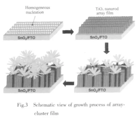
Schematic view Fig.3 showed the growth process of TiO2array-cluster film.The TiO2array evolved from the uniform SnO2layer on FTO substrate because of the structure of TiO2similar to that of SnO2,and the TiO2array was oriented with respect to the substrate surface,while the growth of TiO2rod in the direction with the growth axis parallel to the surface normal of the FTO substrate was blocked by its neighboring TiO2rods.Then some TiO2clusters began to develop from some bulged TiO2rods,afterwards more TiO2clusters developed self-assembly along crystal lattice of the branched rods of the initial TiO2clusters.And schematic view Fig.4 shows the pathway of electron motion in the TiO2array-cluster film.Not only the TiO2clusters like many tentacles favored to absorb more dye to produce many photoelectrons,but also the TiO2rods could provide a fast circulation channel for photoelectrons.
2.4 Effects of initial reactant concentration on the morphology
Fig.5 shows the FESEM images of the TiO2arraycluster films prepared under different dosages of TBOT((A),(a),(A-1):0.02mol·L-1;(B),(b),(B-1):0.04 mol·L-1;(C),(c),(c-1):0.06 mol·L-1;(D),(d),(d-1):0.08 mol·L-1).Some information as follows should be noticed.
①As shown in Fig.5,the morphology of the TiO2film on FTO substrate varied with the dosage of TBOT increasing.The film was only single TiO2array structure when the dosage of TBOT was 0.02 mol·L-1(Fig.5(a)),probably due to TBOT was not enough for the growth of TiO2clusters after the growth of TiO2array.With the dosage of TBOT increasing beyond 0.02 mol·L-1(Fig.5(b),(c),(d)),the novel TiO2arraycluster film was observed.The formation of the twolayer structure was probably determined by the lattice distortion which was affected by the dynamic factors.Futhermore,the dynamic factors was affected by the reactant concentration which was varied with the growth time.
②With the dosage of TBOT increasing,the thickness of the subjacent TiO2array layer was only slightly changed (about 4μm),while the thickness of the supernatant TiO2cluster layer were increasing obviously and can grow to about 41.3μm.So the dosage of TBOT mainly affected the thickness of the supernatant TiO2cluster.
③There was enough space for adsorbing dye between a TiO2rod and its neighboring rods as shown in Fig.5(A)and(A-1).And the TiO2clusters layer was not only thick but also had many branched rods in Fig.5(c),which was advantageous for TiO2film to adsorb more dye and could provide a fast circulation channel for photon-generated electrons,which had potential for improving the light-to-electricity conversion efciency of DSSC.
2.5 Effects of growth time


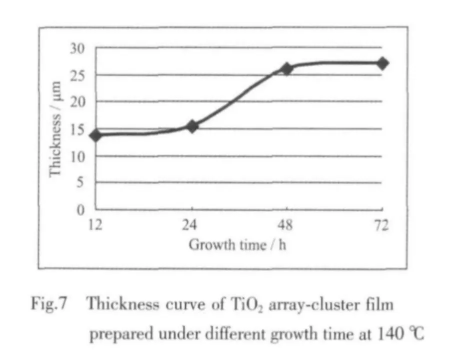
As shown in Fig.6 and Fig.7,the thickness of TiO2array-cluster film changed with the growth time,but the thickness of the subjacent TiO2array layer was only slightly changed.The number of TiO2clusters was very few when the reaction time was 12 h.Then the number became gradually large with the growth time extending from 12 h to 24 h.In the meantime,there were few TiO2rods to branch in the subjacent TiO2array.Nevertheless,the number became rapidly more with the reaction time extending from 24 h to 48 h.The reason was that there were many rods to branch in the neonatal TiO2clusters as shown in Fig.5(B-1)and(c-1).If the growth time was extended from 48 h to 72 h,the number of TiO2clusters became almost unconverted due to the decreasing concentration of TBOT.
2.6 Effects of the angles on forming TiO2 arraycluster
The angles of FTO substrate placed were shown in Fig.8,and Fig.9 shows FESEM images of the TiO2array-cluster films prepared under the same dosage(0.06 mol·L-1)of TBOT at 140 ℃ for 72 h while these FTO substrates were placed at different angles.It was observed there were some irregular round pits and few TiO2clusters distributed on the top of the TiO2array layer prepared at 45-degree and 360-degree angles.In addition,one kind of lipidic substance generated and could float on the surface of reaction solution after the addition of TBOT.Its hydrophobicity made some micro areas on the FTO substrates repelling the reaction solution.While there were more TiO2clusters and few irregular round pits distributed on the top of TiO2array prepared at 90°,especially at 180°angle due to the difficulty of lipidic substance adhering to FTO substrates,which support TiO2films to adsorb more dye.The reason of the difficulty was that the lipidic substance was separated from the FTO substrate by the reaction solution due to its buoyancy when the FTO substrate was placed at 180°angle,while the lipidic substance would adhere to the conductive surface of FTO substrate due to its buoyancy when the FTO substrate was placed at 360°angle or at 45°angle.Moreover,when the FTO substrate was placed at 90°angle,only little lipidic substance could adhere to the conductive surface due to the blocking zone area decreasing,so there were few irregular round pits.In general,it was very important that the FTO substrate was placed at a suitable angle.

2.7 Photovoltaic performance
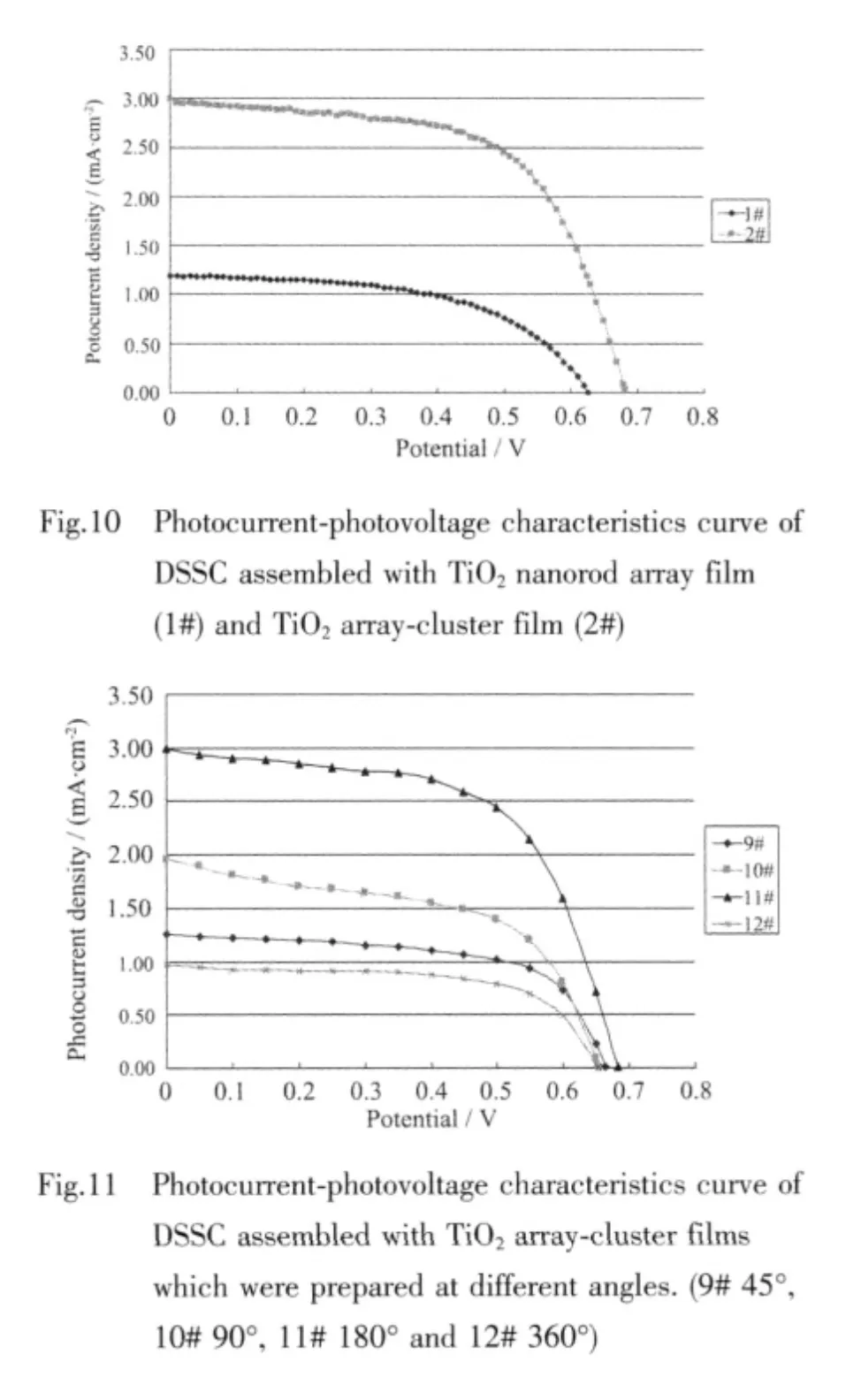
Fig.10 shows the photocurrent-photovoltage characteristics of DSSC assembled with TiO2nanorod array film and TiO2array-cluster film as photoanode.And table 1 shows the results of the photocurrentphotovoltage characteristics parameters for two curves in Fig.10.As shown in Fig.10 and Table 1,the lightto-electricity conversion efciency (η) of DSSC assembled with TiO2array-cluster film was 1.24%which was two times higher than that (0.41%)of DSSC assembled with TiO2nanorod array film due to the high photocurrent.This was because that the TiO2array-cluster film had many clusters like many tentacles which could absorb more dye to produce more photoelectrons.So,more the clusters were,the higher the light-to-electricity conversion efciency was.
Fig.11 shows the photocurrent-photovoltage characteristics curve of DSSC assembled with TiO2array-cluster films prepared at different angles.Table 2 provided the results of the current-voltage characteristics parameters for four curves in Fig.11.The light-to-electricity conversion efciency (η)of DSSC (sample 11#)was 1.24%when the TiO2arraycluster film was prepared at 180°angle,and it was better than that of sample 9#,sample 10#or sample 12#,because it had the most numerous TiO2clusters.


Table 1 Photocurrent-photovoltage characteristics parameters

Table 2 Photocurrent-photovoltage characteristics parameters at different angles
3 Conclusions
A type of novel TiO2array-cluster film was prepared by the low cost hydrothermal method.This type of TiO2film has a two-layer structure with tetragonal rutile phase.Furthermore,the subjacent layer was TiO2array,while the supernatant layer was TiO2cluster.Both section of the layers are formed from TiO2rods which consisted of TiO2nanorods building blocks of which the diameters was about in the range of 25~65 nm.
The thickness of this type of TiO2film could reach to beyond 40μm and the number of the clusters in supernatant layer can be varied by changing initial reactant concentration,growth time or FTOplaced angles.
And without any modification treatment,a lightto-electricity conversion efciency 1.24% of DSSC assembled with TiO2array-cluster film was achieved,which was two times higher than that (0.41%)of DSSC assembled with TiO2nanorod array film due to that the TiO2array-cluster film had many clusters like many tentacles which favored absorb more dye to produce more photoelectrons.
[1]ORegan B,Grätzel M.Nature,1991,353:737-740
[2]Zhang Y B,Feng X J,Jiang L.Sci.Chin.Ser.B:Chem.2007,50:175-178
[3]Zhou Z J,Fan J Q,Wang X,et al.ACS Appl.Mater.&Interf.,2011,3:2189-2194
[4]Kondo Y,Yoshikawa H,Awaga K,et al.Langm.,2008,24:547-550
[5]Gopal K M,Oomman K V,et al.Sol.Ene.Mate.&Sol.Cel.,2006,90:2011-2075
[6]Shin JH,Moon JH.Langm.,2011,27:6311-6315
[7]Agarwala S,Kevin M,Wong A S W,et al.Appl.Mater.&interf.,2010,7:1844-1850
[8]Li D D,Chang P C,Chien C J,et al.Chem.Mater.,2010,22:5707-5711
[9]Chen X B,Mao SS.Chem.Rev.,2007,107:2891-2959
[10]Yang M J,Ding B.J.Phys.Chem.C,2011,115:14534-14541
[11]Cho I S,Chen Z B,Forman A J.Nano Letters,2011,11:4978-4984
[12]Kandiel T A,Dillert R,Feldhoff A,et al.J.Phys.Chem.C 2010,114:4909-4915
[13]Kim S,Sohn K S,Pyo M.Combin.Sci.,2010,doi:org/10.1021/co1000025
[14]Mahajan L H,Mhaske ST,Mater.Lett.,2012,68:183-186
[15]Lia Q,Satura D J G,Kima H,et al.Mater.Lett.,2012,76:169-172
[16]You M K,Kim T G,Sung Y M.Cryst.Grow.&Des.,2010,10:983-987
[17]Long Y Z,Lu Y,Huang Y,et al.J.Phys.Chem.C,2009,113:13899-13905
[18]Acharya K P,Alabi T R,Schmall N,et al.J.Phys.Chem.C,2009,113:19531-19535
[19]Zhu H,Tao Jie,Dong X.J.Phys.Chem.C,2010,114:2873-2879
[20]Liu B,Aydil E S.J.Am.Chem.Soc.,2009,131:3985-3990
[21]LI Ping(李平),LU Hai-Xia(路海霞),QIN Li-Zhao(覃礼钊),et al.Chinese J.Inorg.Chem.(Wuji Huaxue Xuebao),2012,28(9):1855-1860
