Characterization of the Elastic-plastic Region Based on Magnetic Memory Effect
2010-03-01LENGJianchengXUMinqiangLIJianweiandZHANGJiazhong
LENG Jiancheng , XU Minqiang LI Jianwei and ZHANG Jiazhong
1 School of Astronautics, Harbin Institute of Technology, Harbin 150001, China
2 Department of Mechanical Science and Engineering, Daqing Petroleum Institute, Daqing 163318, China
1 Introduction
It is important to evaluate damage degree of ferromagnetic materials nondestructively in engineering field. Magnetic testing methods can be used for this purpose, as magnetic properties in ferromagnetic materials are very sensitive to lattice defects such as dislocation,grain boundary, etc[1]. Especially, magnetic Barkhausen noise (MBN), magnetoacoustic emission (MAE), and metal magnetic memory (MMM) have received considerable current attention[2]since they have potentials in estimating the early damage of ferromagnetic components.
MMM is a passive magnetic testing technique without special magnetizing devices as compared to MBN and MAE. It utilizes variations in the self-magnetic leakage field, and attempts to determine stress concentration zones or micro and macro-defects on the metal surface[3]. Owing to the complexity of magnetomechanical effect to cause MMM phenomenon, experimental research on the physical mechanism of MMM testing has been conducted, in particular static tensile tests, but their findings are not always reconciled. In the elastic deformation stage,magnetic signals transformed from initial random distribution to magnetic ordering state[4], indicating some certain relationship between external stress and magnetic signals[5]. This coincides with remarkably stable rates of change observed by WILSON, et al[6], but it was not an exponential decrease as described by DUBOV[3]. During the plastic deformation stage, there were different views about the variation of MMM signals, that is, with increasing applied stress, the MMM signal could hardly change[4]or increase[7]. In the meanwhile, MMM signal characteristics of critical states were noticed fluctuating on the verge of yield and sharp changing of magnetic polarity on the verge of fracture[8]. It was shown that locations of slip lines accorded with magnetic turning points[9], but there was no simple correspondence between MMM signals and applied load.
Nonetheless, the specimens were not demagnetized prior to testing in the above experiments, and exhibited remanence depending on the residual stress in the material.However, materials with high levels of residual stress are likely insensitive to applied stress[10], and the initial magnetic states will affect or even disturb the magnetic signals. The purpose of the present research is to differentiate the effects of elastic and plastic deformation on magnetic memory signals on the surface of the defective specimen starting from the demagnetization state. The possible reasons underlying different magnetic trends, and the feasibility to evaluate the degree of damage in the plastic region are discussed below.
2 Experimental Section
The material investigated was mild Q235 steel. Tensile specimens of central dimensions 70 mm (length)×23.6 mm(width) ×3 mm (thickness) were cut from the mild steel plate, with a V-shaped notch of depth 3 mm and width 3 mm, as shown in Fig. 1. Three parallel scan lines at intervals of 3 mm were drawn on the surface of the specimen before testing, which were named line 1, line 2 and line 3 sequentially from bottom to top, respectively.
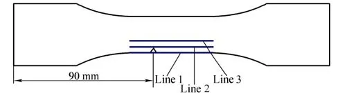
Fig. 1. Geometry of the specimens and measurement lines
The tensile experiments were performed on a universal testing machine Zwick/Roell Z050 at room temperature,using a crosshead speed of 2 mm/min, in accordance with the Chinese National Standard GB/T 228-2002. The specimens were preliminarily demagnetized via a demagnetizer TC-50 and then mounted vertically in the jaws. Load was applied to the specimen in increments, and the normal components of the surface magnetic field intensities, Hy, with a scanning interval of 1 mm along different scan lines were immediately measured by a magnetic indicator TSC-1M-4 with a scanning sensor type 2, up to a visible necking phenomenon. Note that the sensor probe was always perpendicular to the specimen surface with a liftoff of 2 mm during testing. These measurements were made in-situ while the specimens were under load.
3 Experimental Results
The engineering stress-strain curve was measured on the tensile testing machine, which indicated that the yield point is at 21.5 kN and an appreciable crack occurs at a load of 24.5 kN. Fig. 2 shows the variation of Hyalong the scan lines 1, 2 and 3 under different loads, respectively.
As seen in the diagram, there is a significant change in Hydistribution after the first loading as compared to the original state, and slight variation with subsequent increasing loads in the elastic region, whereas abnormal wave crest and trough come into being in the plastic regime.Notable feature is the abrupt change in Hycurve before the macroscopic yield point, and wave height, which is defined as crest minus trough, further increases afterwards, up to break.
The Hycurves have the same wave-form in the plastic stage, and this distribution characteristic can be used to identify the elastic-plastic range. The abnormal wave in the plastic region indicates the most serious stress concentration zone, corresponding to the V-shaped notch.Moreover, the magnitude of wave height reflects the degree of stress concentration. It follows from Fig. 2 that the specimen is more dangerous when loaded to 24.5 kN than that subjected to 21.5 kN.
It should be noted that the wave heights obtained from different scan lines under the same load are different. Fig. 3 illustrates wave crest and trough distributions in Hyafter yielding. It can be seen from the plot that peak signals will increase when the probe gets closer to the notch.
4 Discussion
4.1 Variation regularities in elastic and plastic stages
In the elastic stage, the effect of stress on the magnetization can be considered as an effective field, and thus the change in magnetism with applied stress under a constant magnetic field based on the theory of magnetomechanical effect is given by[11,12]
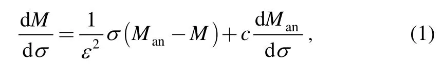
where ε and c are constants, Manpresents the anhysteretic component of magnetization, and the magnetization M contains a reversible component Mrevdue to domain wall bending and an irreversible component Mirrdue to wall displacement.
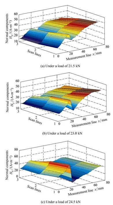
Fig. 3. Abnormal waves in the plastic region
It follows from this expression that the magnetization is related not only to stress σ but also to the displacement Man−M . In other words, the magnetization in the specimen will always head towards the anhysteretic magnetization curve in which the anhysteretic magnetization is the lowest energy state of the domains[13].When most weak domain wall pinning sites are overcome,the magnetization reaches a mostly reversible process, just as shown in Fig. 2.
On the other hand, magnetic behavior becomes more complex in the plastic region. Plastic deformation via slip processes leads to the multiplication of dislocations, which then develop into substructures such as dislocation tangles and cells, thus forming stronger pinning sites for domain walls than individual dislocations[14]. It is difficult to characterize quantitatively the degree to which the strength of pining sites contributes to a change in the Hysignal.However, it is interesting that the wave height increases with the continuing plastic strain. The wave exhibits sharper crest and trough when the specimen undergoes larger deformation, such as necking. This characteristic can be used to distinguish stress concentration zones and corresponding dangerous level.
4.2 Effect of scan lines on wave heights
The wave height, given in Fig. 3, exhibits the dependence on the distance between the scan line and the notch. It can be seen clearly that the characteristic parameter of Hysignal becomes more and more intensive to stress concentration with decreasing distance from the notch.
This can be explained by reference to the V-shaped notch model of magnetic dipole[15]as shown in Fig. 4, in which the width and depth of the crack are 2b and d,respectively.
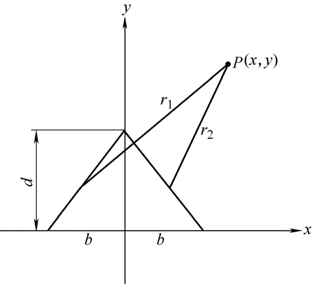
Fig. 4. V-shaped crack
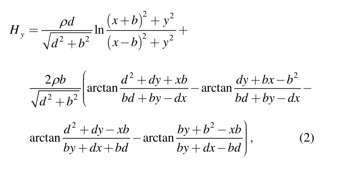
As a result, assuming that magnetic charges are uniformly distributed on the two inclined surfaces, Hycomponent in one certain point P(x, y) is calculated as follows[15]:where ρ is the areal magnetic charge density.
Distributions of Hycomponents were obtained along 3 scan lines with 0 mm, 3 mm, and 6mm distance from the notch respectively, and are illustrated in Fig. 5. The wave crest and trough give a predictable output containing signal features that clearly correspond to the defect position. The variation of wave height with respect to location of the defect has good agreement with the simulation results.
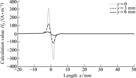
Fig. 5. Hy signal corresponding to different distance from the notch
Compared with the experimental signal, a distinct difference is zero-crossing in the model. Indeed, the specimen was clamped at two ends, causing compressive stress by two clamps. Consequently, the magnetic field will be introduced. Therefore, the value of Hyin the notch is not equal to zero because of the superposition of these two fields.
5 Conclusions
(1) The Hysignals show different variations in elastic and plastic regions due to the influence of either applied stresses or different deformation levels. The abnormal wave in Hysignal observed in the plastic stage can detect the critical state of the macroscopic yield point.
(2) The wave height value in plastic stage depends on the degree of plastic deformation. As the plastic strain increases, the wave height value increases correspondingly.
(3) The wave height value in Hysignal is sensitive to the distance from the defect or stress concentration zone. The closer the distance between the probe and the notch, the sharper the wave crest and trough, which is in accordance with the simulation result based on the magnetic dipole model.
(4) The distinct wave can be used to locate the stress concentration zones, but the value of Hyin the damage zone is not always zero-crossing because of superposition of several magnetic fields in engineering practice.
[1] JILES D C. Review of magnetic methods for nondestructive evaluation[J]. NDT International, 1988, 21(5): 311−319.
[2] DONG Lihong, XU Binshi, ZHU Sheng, et al. Magnetic nondestructive testing of fatigue damage of ferromagnetic material[J]. Nondestructive Testing, 2006, 28(5): 245−248. (in Chinese)
[3] DUBOV A A. A study of metal properties using the method of magnetic memory[J]. Metal Science and Heat Treatment, 1997,39(9−10): 401−405.
[4] DONG Lihong, XU Binshi, DONG Shiyun, et al. The effect of axial tensile load on magnetic memory signals from the surface of medium carbon steel[J]. Chinese Journal of Materials Research, 2006, 20(4):440−444. (in Chinese)
[5] YIN Dawei, XU Binshi, DONG Shiyun, et al. Characteristics of magnetic memory signals for medium carbon steel under static tensile conditions[J]. Journal of Central South University of Technology, 2005, 12(S2): 107−111.
[6] WILSON J W, TIAN Guiyun, BARRANS S. Residual magnetic field sensing for stress measurement[J]. Sensors and Actuators A:Physical, 2007, 135(2): 381−387.
[7] ZHOU Keyin, ZHANG Jing, YAO Entao, et al. Detecting hidden damage in component based on metal magnetic memory effect[J].Journal of Nanjing University of Aeronautics and Astronautics, 2004,36(6): 713−717. (in Chinese)
[8] XING Haiyan, WANG Rixin, XU Minqiang, et al. Stress state detection based on metal magnetic memory theory[C]//Proceedings of the ASME Pressure Vessels and Piping Division Conference,Denver, Colorado USA, July 17−21, 2005: 145−148.
[9] LI Xiaoyang, YUAN Jungang, ZHANG Yiliang, et al. Study on relationship between perpendicular magnetic intensity and plastic deformation propagation[C]//Progress in Safety Science and Technology Volume 4: Proceedings of the 2004 International Symposium on Safety Science and Technology, Shanghai, China,October 25−28, 2004: 2 944−2 948.
[10] CHEN Y, KRIEGERMEIER-SUTTON B K, SNYDER J E, et al.Magnetomechanical effects under torsional strain in iron, cobalt and nickel[J]. Journal of Magnetism and Magnetic materials, 2001,236(1−2): 131−138.
[11] JILES D C. Theory of the magnetomechanical effect[J]. Journal of Physics D: Applied Physics, 1995, 28(8): 1 537−1 546.
[12] LENG Jiancheng, XU Minqiang, XU Mingxiu, et al. Magnetic field variation induced by cyclic bending stress[J]. NDT & E International,2009, 42(5): 410−414.
[13] JILES D C, ATHERTON D L. Theory of ferromagnetic hysteresis[J]. Journal of Magnetism and Magnetic materials, 1986, 61(1−2):48−60.
[14] LO C C H, KINSER E, JILES D C. Modeling the interrelating effects of plastic deformation and stress on magnetic properties of materials[J]. Journal of Applied Physics, 2003, 93(10): 6 626−6 628.
[15] XU Zhangsui, XU Ying, WANG Jianbin, et al. The principle and application of crack leakage magnetic quantitative test[M]. Beijing:National Defense Industry Press, 2005. (in Chinese)
杂志排行

Chinese Journal of Mechanical Engineering的其它文章
- Dynamic Manipulability and Optimization of a Two DOF Parallel Mechanism
- Design of Robot Welding Seam Tracking System with Structured Light Vision
- New Method to Measure the Fill Level of the Ball Mill I—Theoretical Analysis and DEM Simulation
- Comparative Analysis of Characteristics of the Coupled and Decoupled Parallel Mechanisms
- New Hybrid Parallel Algorithm for Variable-sized Batch Splitting Scheduling with Alternative Machines in Job Shops
- Multidisciplinary Design Optimization with a New Effective Method