Dynamic Manipulability and Optimization of a Two DOF Parallel Mechanism
2010-03-01SHAOHuaWANGJinsongWANGLipingandGUANLiwen
SHAO Hua, WANG Jinsong, WANG Liping, and GUAN Liwen
Department of Precision Instrument and Mechanology, Tsinghua University, Beijing 100084, China
1 Introduction
Parallel manipulators have received much attention in terms of industrial application, high speed machines,motion simulators, and so on, due to their relative advantages of high stiffness, good dynamic characteristic,and high payload capability[1,2].
The dynamic dexterity is an important issue that should be considered for problems of manipulator design[3]. It is an evaluation on the efficiency and easiness for performing required manipulator tasks. Some indices for evaluating dynamic dexterity such as dynamic manipulability[4]have been proposed. Dynamic manipulability ellipsoid (DME)[5]is an effective tool to perform task space dynamic analysis of robotic manipulators, and it is a measure of the dynamic performance of a robot manipulator based on the maximum acceleration of the end-effector. CHIACCHIO, et al[6],presented a new definition of dynamic manipulability ellipsoid for redundant manipulators. DOTY, et al[7],proposed an alternative formulation of the manipulability ellipsoid by changing the scale factors or performing a rigid-body transformation on the kinematic vectors.
Some other measures for evaluating dynamic dexterity have been proposed and applied. The acceleration radius[8]was also proposed as performance measure, this method obtained the minimum value of upper boundaries for the feasible acceleration of an end-effector in the task space.ASADA, et al[9,10], proposed a generalized inertial ellipsoid(GIE) that allowed the distributed mass system of the manipulator to be measured as a single-point mass system at the end-effector. TADOKORO, et al[3], defined a measure of stochastic dynamic manipulability by applying the stochastic interpretation to the dynamic problem, and the stochastic dynamic manipulability evaluates the dynamic dexterity considering the deviation of directions of end-effector acceleration. WU, et al[11,12], applied both DME and GIE to some planar two DOF parallel manipulators for dynamic manipulability analysis.
In this paper, the dynamic manipulability analysis and optimization of a two DOF parallel manipulator are investigated. Utilizing the virtual work principle, a compact dynamic model of the manipulator is derived. The reciprocal of the condition number of generalized inertia matrix is proposed for evaluating the dynamic dexterity of a manipulator. A global dynamic conditioning index, which is based on the distribution of the condition number of generalized inertia matrix over the task workspace, is proposed for dynamic optimization of the manipulator. The index is applied to redesign the manipulator by changing the link lengths. The dynamic manipulability of the manipulator is evaluated by DME and GIE. The dynamic manipulability of the improved manipulator is compared with that of the original manipulator.
2 Structure Description
The two DOF parallel mechanism is shown in Fig. 1.The mechanism is composed of a moving platform B1B2,two active kinematic chains O1A1B1, O2A2B2, and a passive kinematic chain O3A3B3. The chains O1A1B1and O3A3B3have the same structure, and their movements are synchronization by a parallelogram, so providing the moving platform with a two-axis translational moving capability in x-y plane. The chain O1A1B1is a RRR linkage driven along the z-axis, and the other chain O2A2B2is a RSS linkage driven along the x-axis.
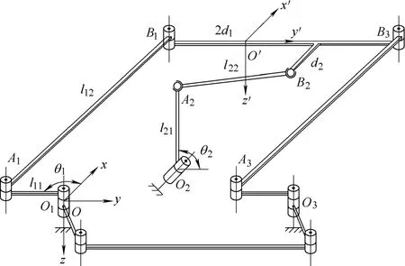
Fig. 1. Kinematic model of the two DOF parallel mechanism
3 Kinematic Analysis
3.1 Inverse kinematics of the mechanism
As illustrated in Fig. 1, the coordinate system O −xyz is attached to base1O and a moving coordinate systemis fixed to the moving platform. 21d is the width between joint point1B and2B along the y-axis,and d2is the width between them along the x-axis.
Let the coordinate of origin O′ bewhere p is the posture of the moving platform, andz is a constant. The coordinates of B1and2B in coordinate system O ′ x ′y z′′− can be expressed asAccording to Fig. 1, the following equations can be obtained:

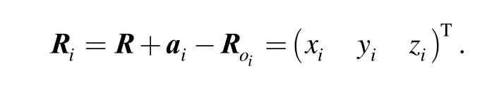
whereioR —Coordinate ofiO,
Eq. (1) can be rewritten as
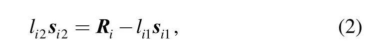
whereiR—Vector from Oito Bi,
The following equation can be obtained by taking the norm on both sides of Eq. (2):
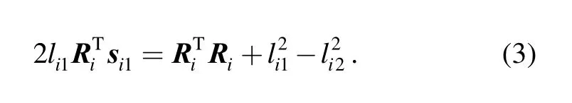
(1) For the case of i=1 , s11can be described aswhere θ1is the angle between link l11and x-axis, so the following equation can be obtained from Eq. (3):

The solution of this equation can be written as
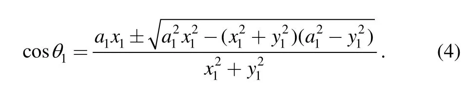
Direct kinematic singularities occur when links O1A1and A1B1are collinear. To avoid the inverse kinematic singularity, the “±” of Eq. (4) should be only “-”. Thus,the vector of link l12is obtained as
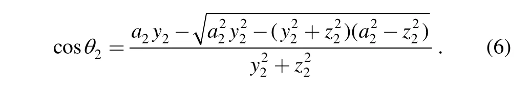
(2) The other case of i=2,s21is written aswhere θ2is the angle between link l12and y-axis, so the following equation can be obtained from Eq. (3):
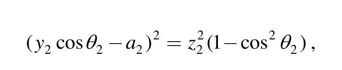
Similar to chain O1, the solution to this equation for chain O2should be
Vector s22can be obtained from Eq. (2):
3.2 Jacobian matrix of the inverse kinematic problem
Taking the time derivative of Eq. (1) leads to
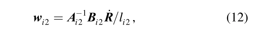
Then, multiplying both side byEq. (8) can be written as
(1) For the case of i=1 , link l11is always in x-y plane,thus w11should be, combining w11and Eq. (9) lead to
(2) Similarly, angular velocity vector w21can be defined asand the following equation can be obtained:
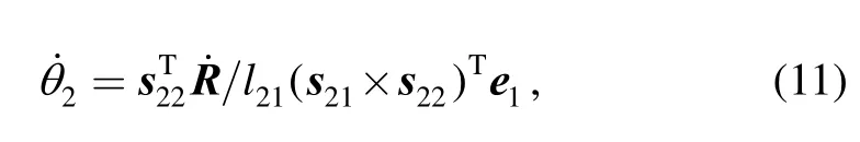
The idle DOF spinning along AiBiof link li2can be neglected, the result ofshould be 0. Thus,multiplying both sides of Eq. (8) byandand assembling in matrix form lead to
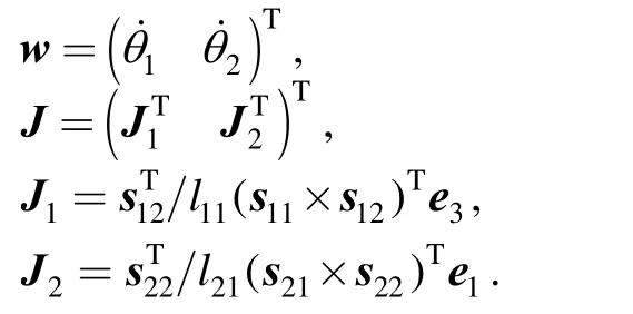
The Jacobian matrix of the inverse kinematic can be obtained from Eqs. (10–11):
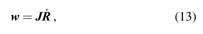
where
4 Dynamic Model Based on Virtual Work Principle
4.1 Acceleration analysis
Taking the time derivative of Eq. (8) leads to
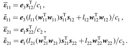
(1) For the case of i=1 , link l11is always in x-y plane,thus ε11should be, combining ε11and Eq. (14) lead to
(2) Similarly, the angular acceleration vector ε21can be defined asand the following equation can be obtained:
So the angular velocity of link OiiA can be written as

where
Cross multiplying both sides of Eq. (15) by si2lead to
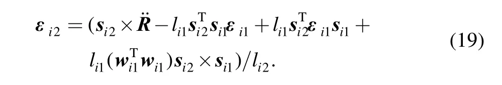
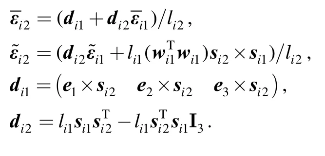
It can be rewritten as
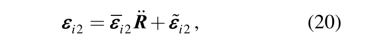
where
4.2 Particular velocity matrix and particular angle velocity matrix
The virtual work principle[13,14]was employed to derive the dynamic model with a more compact form. First, the particular velocity and particular angular velocity matrix should be determined for dynamic modeling. For the purpose of finding the particular velocity matrix, pointis selected as the pivot point of barandiB is the pivot point of link AiiB. The mass center O′ of the moving platform is regarded as the pivot point of the platform. Then, the partial velocity matrix and partial angular velocity matrix of each part can be computed.
Since bar OiiA has only the rotational capability, the partial velocity matrix can be expressed as
According to Eqs. (10)–(11), the partial angular velocity matrix of bar OiiA is given by as follows:
Since link AiiB is connected to the moving platform,thus, the partial velocity matrix of pointiB can be written as
where I3-3-order unit matrix.
On the basis of Eq. (12), the partial angular velocity matrix can be expressed as

The moving platform can not rotate in this mechanism,the partial velocity matrix and partial angular velocity matrix are written as
4.3 Inertial forces and moments of moving parts
The inertial force and moment of each moving part about the part’s pivot point is derived by utilizing Newton-Euler formulation.1im , mi2and mNare denoted as the masses of links OiiA, AiiB and the moving platform,respectively. I1i, Ii2and INare denoted as the moment of inertial of links OiiA, AiiB and the moving platform about each pivot point, respectively.
The inertial force and moment of link OiiA aboutiO can be expressed as follows:
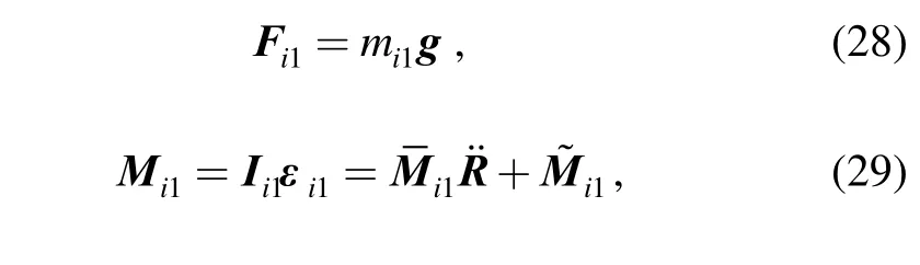
where g is the gravitational acceleration vector and, and
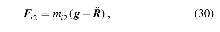
The inertial force and moment of link AiiB aboutiB can be expressed as follows:

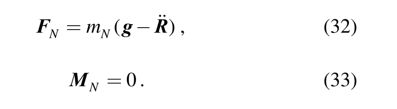
The inertial force and moment of the moving platform about O′ can be expressed as
4.4 Dynamic model
The dynamic formulation of the parallel manipulator can be derived based on the virtual principle
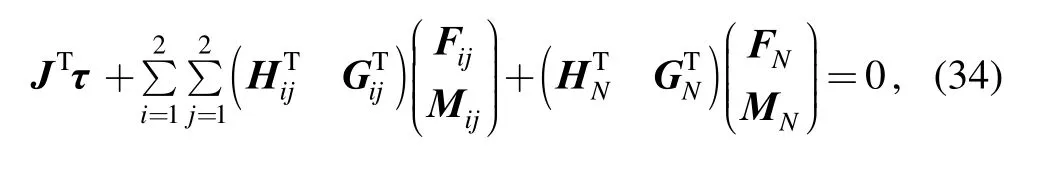

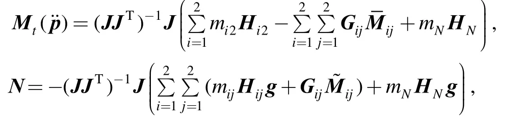
where and Ν consists of the centrifugal, coriolis, and gravitational forces.can be rewritten asfor the reason that z is a constant. Thus,Eq. (35) was modified in the form
5 Dynamic Manipulability Evaluation and Optimization
5.1 Performance indices
There are many performance indices for evaluating dynamic manipulability, but DME and GIE were conventionally used to evaluate the dynamic manipulability of a manipulator. As addressed in Refs. [9] and [11], both DME and GIE are based on the relationship between the generalized acceleration of the end-effector and the generalized inertia torques of the joints. Thus, the force N can be neglected and Eq. (36) can be rewritten in a unified form
where M ( ˙p˙) is the generalized inertia matrix.
On the basis of the GIE, the moving platform can easily accelerate in the direction of major axis of the ellipsoid and hardly in the direction of minor axis. The lengths of the principal axes represent the maximum and minimum singular values of the inertia matrix, and the difference between them stands for the anisotropy of the accelerating performance, which is isotropic when the lengths of the principal axes are the same.
In the dynamic optimum design, if the issue that the accelerating capabilities along all directions should be more isotropic is considered, the condition numberDκ of the generalized inertia matrix is proposed to quantify the dynamic dexterity of the manipulators, which is defined as
where1δ and2δ are the minimum and maximum singular values of the inertia matrix.
The dynamic dexterity can be evaluated bysinceis better behaved than κDitself over the overall workspace. For the purpose of obtaining a measure of the global behaviour of the manipulator dynamic condition number, similar to that introduced in Ref. [15], a global dynamic conditioning indexDη is proposed as follows:
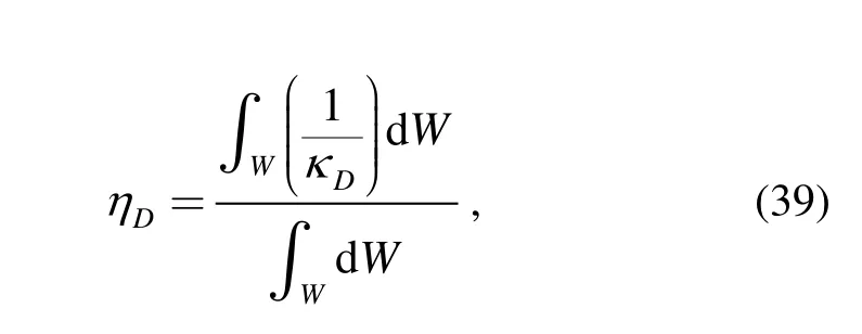
where W is the task workspace of the manipulator.
The index defined in Eq. (39) is to maximize over the space of manipulator parameters. Thus, the closer to unity the index is, the better the overall dynamic dexterity of the manipulator is.
5.2 Dynamic manipulability analysis
As an example to investigate the dynamic dexterity, the designed motion parameters and inertial parameters of the manipulator are given in Table.
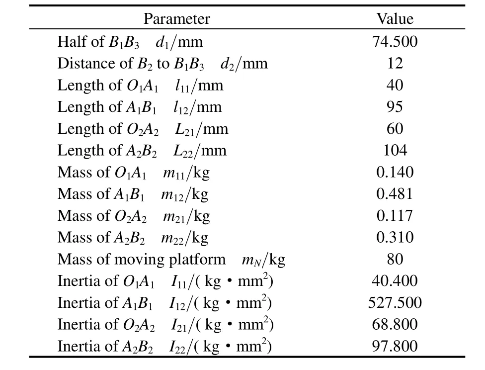
Table. Geometrical and inertial parameters
The task workspace of the manipulator is defined as a rectangle area with width 30 mm and height 30 mm.
Fig. 2 shows the generalized inertia ellipsoid of the task workspace. The moving platform can possess a maximum(minimum) acceleration in the direction of the ellipsoid’s major (minor) axis. The larger the area of ellipsoid, the larger is the output acceleration. Fig. 2 shows that the accelerating capability of the point is maximum along x-axis and minimum along y-axis.
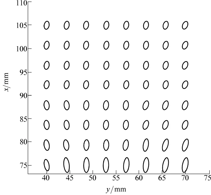
Fig. 2. Distribution of generalized inertia ellipsoid
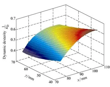
Fig. 3. Dynamic dexterity of the inertia matrix
5.3 Dynamic manipulability optimization
l11and l21are optimized by maximizingDη over the manipulator’s parameter space on the basis ofDη . It is defined that
The distribution ofDη and its counter map over the parameter space are shown in Fig.4 and Fig.5,respectively.
From Fig. 4 and Fig. 5, it can be seen thatDη get the maximum value 0.791 6 whenandOn the basis of ηD, this optimized parameter design result is applied to the manipulator.Fig. 6 and Fig. 7 show the dynamic performances of the optimized mechanism.
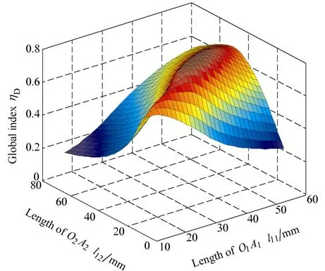
Fig. 4. Distribution of Dη over the parameter space
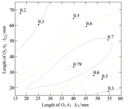
Fig. 5. Counter map of Dη over the parameter space
The generalized inertia ellipsoid of the optimized mechanism in the task workspace is shown in Fig. 6, from which one can see that the axis of the ellipsoid along the y-axis is much longer than that of the origin mechanism,and the area of the ellipsoid is lager than the older one.That means the optimized mechanism can get larger output acceleration over the workspace and along the y-axis with the same input.
Fig. 7 shows the dynamic dexterityin the same workspace W. It can be seen that the dynamic dexterity is less than 1.0, and more than 0.6, the dynamic dexterity is bigger than that of the original mechanism, which is shown in Fig. 3. That means the optimized mechanism has better dynamic performance.
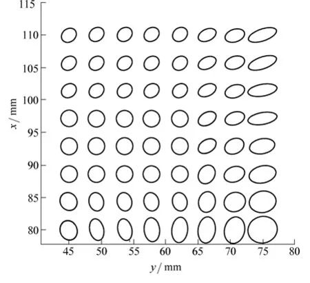
Fig. 6. Distribution of GIE of the optimized mechanism
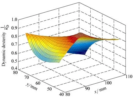
Fig. 7. Dynamic dexterity of the optimized mechanism
6 Conclusions
(2) The dynamic manipulability optimization is performed based onDη . A design result is given with respect to a desired task workspace, then the parameters of the manipulator are improved by consideringDη . The optimized manipulator shows better dynamic performance than the original one.
[1] LIU Xinjun. Optimal kinematic design of a three translational DoFs parallel manipulator[J]. Robotica, 2006, 24: 239–250.
[2] GAO Feng, PENG Binbin, ZHAO Hui, et al. A novel 5-DOF fully parallel kinematic machine tool[J]. International Journal of Advanced Manufacturing Technology, 2006, 31: 201–207.
[3] TADOKORO S, KIMURA I, TAKAMORI T. A measure for evaluation of dynamic dexterity based on a stochastic interpretation of manipulator motion[C]//Proceedings of the Fifth International Conference on Advanced Robotics, Pisa, Italy, 1991: 509–514.
[4] YOSHIKAWA T. Analysis and design of articulated robot arms from the viewpoint of the dynamic manipulability[C]//The Third International Symposium of Robotics Research, Cambridge, MA,USA, 1985: 273–279.
[5] YOSHIKAWA T. Dynamic manipulability of robot manipulators[J].Journal of Robotic Systems, 1985, 2(1): 113–124.
[6] CHIACCHIO P, CONCILIO M. The dynamic manipulability ellipsoid for redundant manipulators[C]//Proceedings of IEEE International Conference on Robotics and Automation, Leuven,Belgium, May 16-20, 1998: 95–100.
[7] DOTY K L, MELCHIORRI C, SCHWARTZ E M, et al. Robot manipulability[J]. IEEE Transactions on Robotics and Automation,1995, 11(3): 462–468,.
[8] GRAETTINGER T J, KROGH B H. The acceleration radius: A global performance measure for robotic manipulators[J]. IEEE Journal of Robotics and Automation, 1988, 4(1): 60–69.
[9] ASADA H, TOUMI K Y. Analysis and design of a direct-drive arm with a five-bar-link parallel drive mechanism[J]. ASME Journal of Dynamic Systems Measurement and Control, 1984, 106(3): 225–230.
[10] ASADA H. A geometrical representation of manipulator dynamics and its application to arm design[J]. J. Dyn. Syst., Meas. Control,1983, 105(3): 131–135.
[11] WU Jun, WANG Jinsong, LI Tiemin, et al. Dynamic dexterity of a planar 2-DOF parallel manipulator in a hybrid machine tool[J].Robotica, 2007, 26(1): 93–98,.
[12] WU Jun, WANG Jinsong, WANG Liping, et al. Dimensional synthesis and dynamic manipulability of a planar two-degree-offreedom parallel manipulator[J]. Proceedings of the I MECH E Part C: Journal of Mechanical Engineering Science, 2008, 222(6):1 061–1 069.
[13] ZHANG C D, SONG S M. An efficient method for inverse dynamic of manipulators base on the virtual work principle[J]. Journal of Robotic Systems, 1993, 10(5): 605–627.
[14] TSAI L W. Solving the inverse dynamics of a Stewart-Gough manipulator by the principle of virtual work[J]. Journal of Mechanical Design, 2000, 122(1): 3–9.
[15] GOSSELIN C M, ANGELES J. A global performance index for the kinematic optimization of robotic manipulators[J]. ASME Journal of Mechanical Design, 1991, 113(3): 220–226.
杂志排行

Chinese Journal of Mechanical Engineering的其它文章
- Design of Robot Welding Seam Tracking System with Structured Light Vision
- New Method to Measure the Fill Level of the Ball Mill I—Theoretical Analysis and DEM Simulation
- Comparative Analysis of Characteristics of the Coupled and Decoupled Parallel Mechanisms
- New Hybrid Parallel Algorithm for Variable-sized Batch Splitting Scheduling with Alternative Machines in Job Shops
- Multidisciplinary Design Optimization with a New Effective Method
- Reliability Analysis of Electromechanical Systems with Degraded Components Containing Multiple Performance Parameters