Comparative Analysis of Characteristics of the Coupled and Decoupled Parallel Mechanisms
2010-03-01ZENGDaxingHOUYuleiLUWenjuanandHUANGZhen
ZENG Daxing, HOU Yulei, LU Wenjuan, and HUANG Zhen
College of Mechanical Engineering, Yanshan University, Qinhuangdao 066004, China
1 Introduction
Just as mentioned on philosophy, things are always the unity of opposites, and this is also confirmed in the research process of mechanism. When the serial mechanism is forging ahead in its development, the parallel mechanism (PM), in which the fixed base and the moving platform are connected by two or more limbs, becomes the research focus of the international academic and engineering field gradually.
Compared with the serial mechanism, the parallel mechanism has some outstanding properties in certain aspects, such as a large payload to weight ratio,considerable stiffness, low inertia, high dynamic performances, and so on. The advantages of the PM are closely related to the coupling between the limbs. While it is no other than coupling that makes the PM possess some disadvantages, including smaller workspace, lower dexterity, more complex control command, and multiple singularities. The difficulties in the structural design, static and dynamic analysis and development of control system of the PM are also caused by the existence of the coupling,which restrict the applications of the PM.
Then the decoupled parallel mechanism (DPM), in which there exists a one-to-one correspondence relationship between the input and output variables, attracts many scholars’ interests[1–3]. In this paper, the kinematic pairs will be denoted with following symbols: P for prismatic pair, R for revolute pair, U for universal pair, and C for cylindrical pair. HUANG and LI[4]invented a fully-isotropic 3-CPR three-degrees-of-freedom (3-DOF) decoupled translational PM. CARRICATO, et al, discussed the general problem of the topological synthesis and classification of translational PMs, and investigated both their constraint and direct singularities[5], and presented a pointing parallel mechanism U-PUR-PRRU with fully decoupled degrees of freedom[6].KONG and GOSSELIN proposed a 3-CRR 3-DOF translational parallel manipulator with linear actuators[7]and three classes of input-output decoupled parallel manipulators with 2 to 4 DOFs using a geometric approach[8]. KIM and TSAI[9]introduced a 3-DOF Cartesian parallel manipulator and performed its optimal design. LI, et al[10], presented a 3-DOF translational parallel manipulator named R-CUBE which has decoupled motion in three axes. GOGU[11]presented singularity-free fully-isotropic parallel wrists with 2-DOF and proposed a method for structural synthesis based on the theory of linear transformations.
Generally speaking, the DPM not only keeps the principal advantages of the PM, but also avoids the main drawbacks of the general coupled PM. To reveal the separated characteristics of the coupled and decoupled PMs,taking the 3-RPUR PM and the 3-CPR PM as example respectively, this paper focuses on their comparative analysis.
The organization of this paper is as follows: Following the introduction, the structure composition of the 3-RPUR PM and the 3-CPR PM are described and their modes of motion are analyzed in section 2. Displacement analysis,including the forward and inverse displacement solution, is performed in section 3. Section 4 concerns performance analysis, including workspace, dexterity, velocity, payload capability and stiffness etc. The paper is concluded in section 5, summarizing the present work.
2 Mechanism Features Analysis
As shown in Fig. 1, the 3-RPUR PM is composed of an upper platform, a lower platform and three uniform limbs connecting the two platforms with R, P, U and R in turn.The connection points are located on a circumcircle symmetrically 120° apart. The axis of the R pair connected with the lower platform is parallel with one of the two axes of the U pair, the motion direction of the P pair is perpendicular to these two parallel axes, and the other axis of the U pair is parallel with the axis of the R pair connected with the upper platform. Taking the upper and lower platform as the moving platform and the fixed base respectively, we set up the moving coordinate system o-xyz and the stationary coordinate system O-XYZ with their origins located at the geometrical center of the upper and lower platform respectively. In addition, the P pairs of three limbs are selected as the input pairs. The circumcircles of the upper and lower platform are denoted as r and R,respectively. The distance between Ai(i=1, 2, 3) and Bi(i=1, 2, 3) is denoted as li(i=1, 2, 3), and the length of the pole BiCi(i=1, 2, 3) is supposed as L.
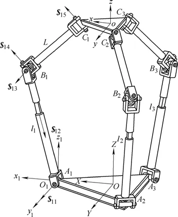
Fig. 1. Schematic diagram of 3-RPUR 3-DOF PM
The coordinate system oi-xiyizi(i=1, 2, 3) is built with its origin located on the center of the R pair of the ith limb connected with the fixed base, in which yiaxis is consistent with the axis of this R pair, and ziaxis is perpendicular to the fixed base plane. Selecting the limb A1B1C1as example,we can obtain the screw system of the limb in o1-x1y1z1as follows:
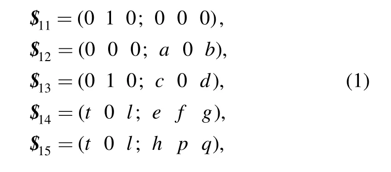
where a, b, c, d, t, l, e, f, g, h, p and q are all finite non-zero real number.
The reciprocal screw of the screw system in Eq. (1) is
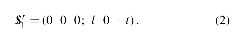
Similarly, the reciprocal screwsandof the other two limbs A2B2C2and A3B3C3can be solved, and they are also perpendicular to the plane formed by the two rotational axes of U pair of the corresponding limb respectively. Obviously,andare noncoplanar which accounts for that they are linear independent. Therefore the three rotations of the moving platform are constrained completely, that is, the mechanism only has three translations.
The mobility can also be obtained by the modified Kutzbach-Grübler criterion[12]. What should be noted is that the 3-RPUR PM has not common constraint, passive DOF,and redundant constraints, and then its DOF is
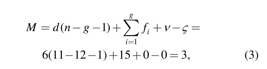
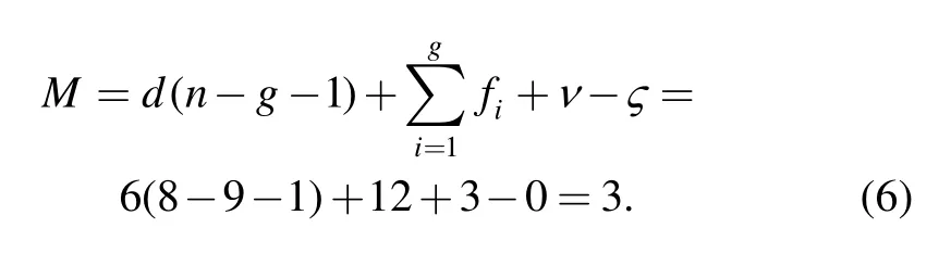
where M is the DOF of the PM; d the order of the mechanism, and d= 6−λ ; λ the common constraint;n denotes the number of links; g the number of kinematic pairs; fithe freedom of the ith pair; ν the number of redundant constraints; ς the passive degree of freedom.
Fig. 2 shows the schematic diagram of the 3-CPR PM with three identical limbs. Each limb connects the moving platform and the fixed base with the R pair and the C pair,respectively. The axis of the R pair is parallel with that of the C pair, and the motion direction of the P pair, which locates between the R pair and the C pair, is perpendicular to these two parallel axes. In addition, the axes of the C pairs of the three limbs keep perpendicular one another.The stationary coordinate system O-XYZ is set up with its origin located at the intersection of the three C pairs, and the X, Y and Z axis are collinear with the axis of the three C pairs respectively. The moving coordinate system o-xyz is set up with its origins located at the geometrical center of the triangle B1B2B3, and the x, y and z axes are parallel with that of the stationary coordinate system respectively. The translation of the three C pairs are selected as the input, and the input quantity are denoted as L11, L21and L31respectively. The vertical distance from the origin of the coordinate system o-xyz to the axis of the R pair connecting with the moving platform is denoted as m, and the length of the link AiBi(i=1, 2, 3) is denoted as Li(i=1, 2, 3).
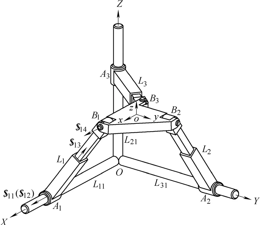
Fig. 2. Schematic diagram of 3-CPR 3-DOF PM
Taking the limb A1B1as example, we can obtain its screw system as follows:
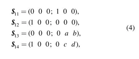
where a, b, c and d are all finite non-zero real number.
Then the reciprocal screws of the screw system of the limb A1B1can be solved as
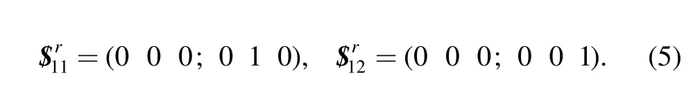
Similarly, the reciprocal screwsandof the limb A2B2which around X axis and Z axis respectively, andandof the limb A3B3which around X axis and Y axis respectively, can also be solved.
Then it is obvious that these six reciprocal screws constrain all the rotation of the moving platform and there are three redundant constraints, so this PM only has three translations.
By the modified Kutzbach-Grübler criterion, the DOF of the 3-CPR PM can be solved as
3 Displacement Analysis
3.1 Inverse displacement solution
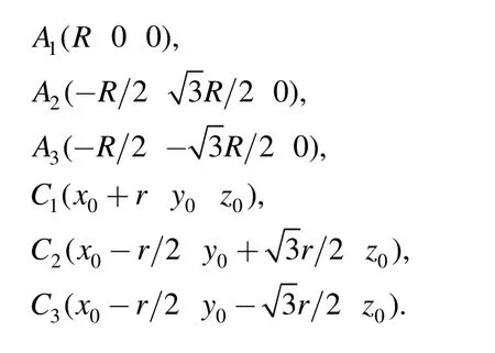
For the 3-RPUR PM, the coordinates of points Aiand Ci(i=1, 2, 3) with respect to O-XYZ can be expressed as follows:
On one hand, the trajectory of point Bi(i=1, 2, 3) locates on a circle of which takes Ci(i=1, 2, 3) as the centre and L as radius, on the other hand, Bialso locates on a circle of which takes Ai(i=1, 2, 3) as the centre and li(i=1, 2, 3) as radius. Then the input parameter1l, l2and3l can be obtained as
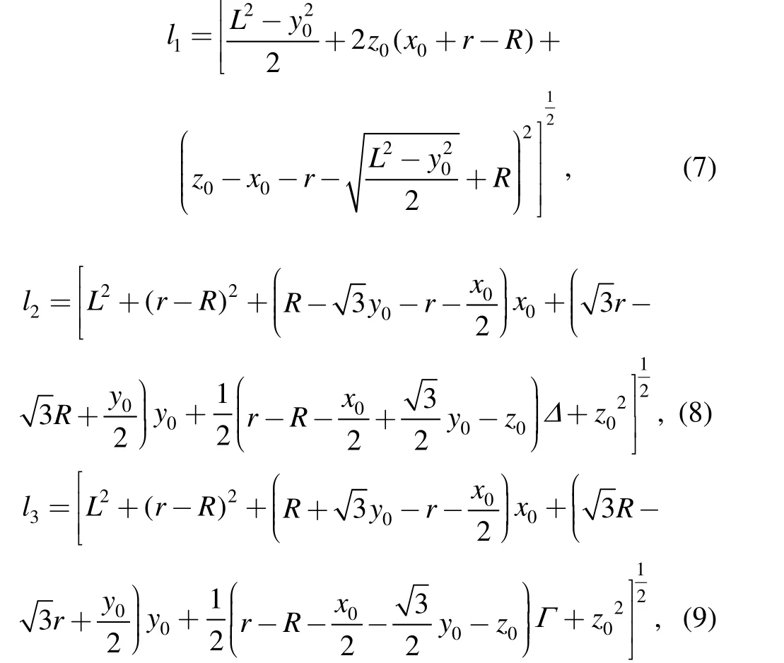
where
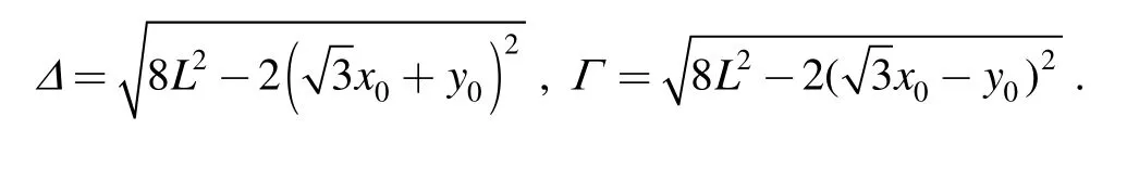
When derivatives are taken with respect to time for Eqs.(7), (8) and (9), the relationship between the input and output velocity can be expressed with matrix form as
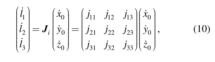
where
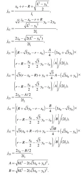
If matrix Jiis not singular, the Jacobian matrix of the 3-RPUR PM can be solved as

For the 3-CPR PM, the relationship between the input and output can be directly obtained from Fig. 2, that is
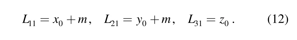
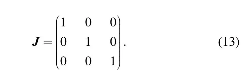
Taking derivatives with respect to time for Eq. (12), the Jacobian matrix of the 3-CPR PM can be obtained as
3.2 Forward displacement solution
For the 3-RPUR PM, the forward displacement solution needs to solve the simultaneous Eqs. (7), (8) and (9) with knownNevertheless, it is comparative difficult to obtain the closed solution by using current methods.
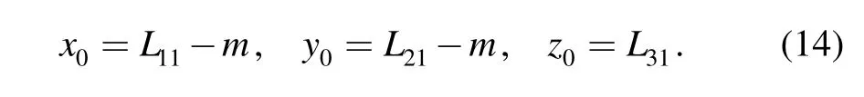
While for the 3-CPR PM, if the driving inputis determined, the location coordinates of the moving platform are
From the above derivation, it can be seen that, for the 3-RPUR PM, the input-output equations are highly coupled and the expression of Jacobian matrix is complex, which will result in the difficulty in its inverse and forward displacement solution, and bring out some disadvantages for the performance analysis. While the Jacobian matrix of the 3-CPR PM is a constant matrix, and the inverse and forward displacement solution of this mechanism is so simple to solve, which is convenient for further research and practical application.
4 Perfromance Analysis
4.1 Normalization of structural parameters
The theory of physical model of the solution space[13–15]provides a tool for the research of the relationship between the performance evaluation indices and the structural parameters. By using the performance indices atlases, we can determine the domain of structural parameters with good values of the indices conveniently.
The three limbs of the 3-RPUR PM possess the same structure and distribute symmetrically, then without consideration of the twist angle between the axis of the pair and the moving platform or the fixed base, this mechanism has three variable parameters r, R and L. For the simplification consideration, we normalize the structural parameters with linear dimensions as follows:
Eq. (15) should subject to
In the following analysis, the initial values of structural parameters of the 3-RPUR PM are supposed as r′=0.6 ,
For the similar consideration, the dimensionless input parameters of 3-RPUR PM can be expressed as
For the 3-CPR PM, there is only one variable parameters m, which does not influence the output and the Jacobian matrix of the PM without consideration of the twist angles between the axes of pairs.
For the comparability between the 3-RPUR and the 3-CPR PM, the same variable range of the input is set as follows:

4.2 Workspace analysis
As one of the important kinematics indices, the size of the workspace determines the range of motion of the mechanism. For a PM with good application value in practical engineering, the shape of its workspace should be regular, and the mechanism should have better kinematics performances and do not exist singular configuration in the whole workspace.
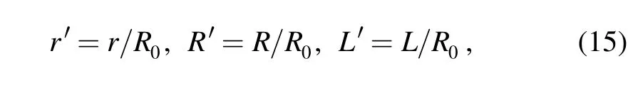
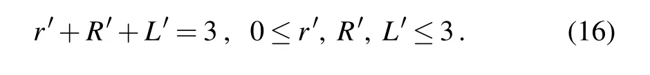
According to Eqs. (7), (8), (9), (15) and (16), a mushroom workspace of the 3-RPUR PM is obtained and shown in Fig. 3. The workspace distributes symmetrically 120° apart and the thickness of the center is about 0.6.
Fig. 3. Workspace of the 3-RPUR PM
On the basis of the theory of physical model of the solution space, the workspace of the 3-CPR PM is described as shown in Fig. 4. This workspace is just like a cube of which each side is 1, and there does not exist singular point in the whole workspace.
By comparing Fig. 3 and Fig. 4, it can be seen that the available workspace of the 3-CPR PM is bigger than that of the 3-RPUR PM, so the application fields of the former should be wider than the latter from this point.
Fig. 4. Workspace of the 3-CPR PM
4.3 Dexterity analysis
Generally speaking, the condition number of the Jacobian matrix is taken as the performance evaluation index for the dexterity analysis[16], and the bigger the condition number is, the worse the dexterity is. The condition number of the Jacobian matrix can be defined as[17]
where σmax( J ) and σmin( J )are the maximum and minimum singular values of Jacobian matrix, respectively.
According to Eqs. (10), (11), and (19), the dexterity atlases of the 3-RPUR PM are shown in Fig. 5.
Fig. 5. Dexterity atlases of 3-PRUR PM
In fact, the condition number defined in Eq. (19) only describes the dexterity of the mechanism in a certain pose,to give an overall evaluation on the dexterity of a certain workspace, the global conditioning index, proposed by GOSSELIN, et al[18], is defined as follows:
whereJη denotes the global conditioning index, andW denotes the workspace of the mechanism.
The global conditioning index is essentially the average of the reciprocal of the condition number of the Jacobian matrix in a certain workspace. The biggerJη is, the higher the dexterity of the mechanism is.
According to Eq. (20), the global conditioning index of the 3-RPUR PM can be calculated out, which is equal to 0.046 414 and is far smaller than 1. This shows that the dexterity of this mechanism is very poor.
While for the 3-CPR PM, according to Eq. (13), the condition number of the Jacobian matrix is equivalent to 1,which indicates that the global conditioning index is equal to 1 and keeps invariable in the whole workspace. So it can be said that the 3-CPR PM possesses isotropic kinematic performances and its dexterity is very good.
4.4 Velocity analysis
Denoting the input and output velocity vector of the 3-RPUR PM asand V respectively, we have

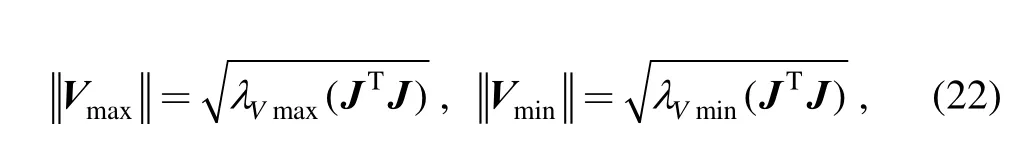
According to Eqs. (10), (11) and (22), the velocity index atlases of the 3-RPUR PM are plotted and shown in Fig. 6.
Being similar to the condition number discussed above,the velocity extremum only describes the maximum or minimum of the velocity of the mechanism on a certain point. For the purpose of evaluating the velocity performance in a certain workspace, the global velocity indices[19]are defined as follows:
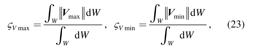
where ςVmaxand ςVminare the maximum and minimum global velocity indices, respectively; W denotes the workspace of the mechanism.
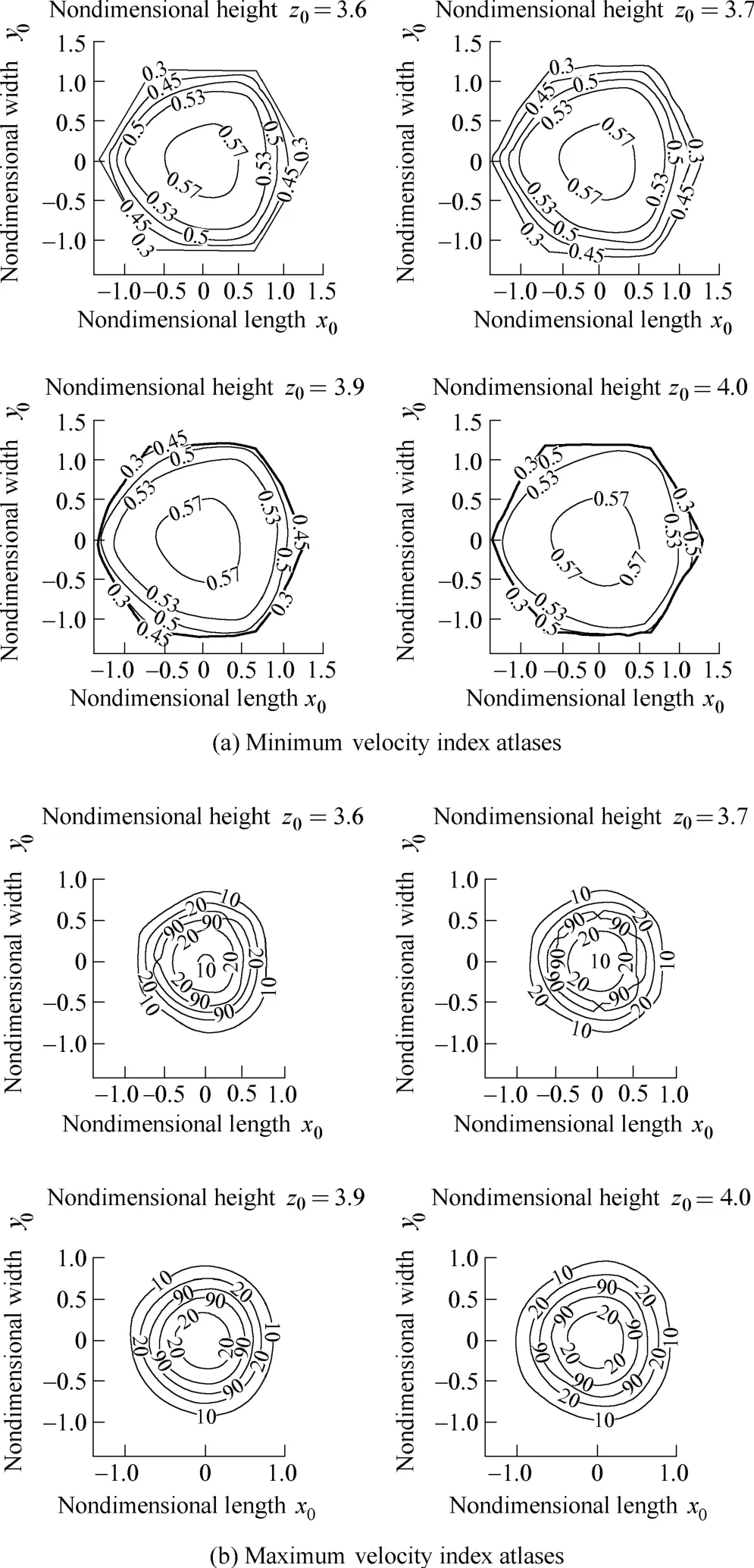
Fig. 6. Atlases of the velocity index of the 3-RPUR PM
Then the maximum and minimum global velocity indices of the 3-RPUR PM in the whole workspace can be solved,which are equal to 68.393 and 0.543 7, respectively.
Owing to the Jacobian matrix of the 3-CPR PM is a unit matrix, the maximum and minimum of the output velocity vector are both equal to 1, and keep invariable in the workspace. Therefore the maximum and minimum global velocity indices of the 3-CPR PM are also equivalent to 1.
From the above analysis, it can be seen that the minimum global velocity index of the 3-CPR PM is bigger than that of the 3-RPUR PM, while the condition of the maximum global velocity index is just opposite to that of the minimum one. So the coupled 3-RPUR PM is more suitable for the application which requires high velocity in some directions and low velocity in the other directions,and the decoupled 3-CPR PM is more suitable for the situation requiring the uniform velocity in all directions.
4.5 Payload capability analysis
The relationship between the generalized force vector f and the external force vector F applied to the end actuator of the mechanism can be expressed as

where G is the force Jacobian matrix, and
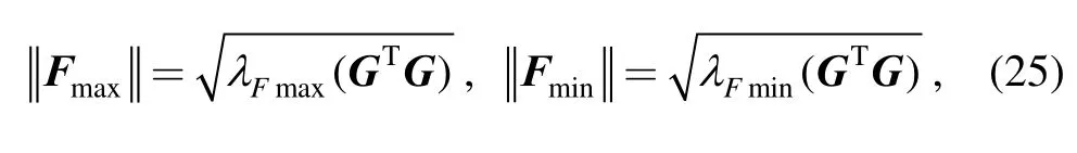
According to Eqs. (10), (11) and (25), the payload capability index atlases of the 3-RPUR PM are plotted and shown in Fig. 7.
The maximum or minimum obtained from Eq. (25) only denotes the payload capability of the mechanism when the moving platform locates on a certain position in the workspace, then to describe the payload capability in the whole workspace, the global payload capability indices are defined as follows[20]:
where ςFmaxand ςFminare the maximum and minimum global payload capability indices, respectively; W denotes the workspace of the mechanism.
Then the maximum and minimum global payload capability indices of the 3-RPUR PM in the whole workspace can be solved, which are equal to 1.865 7 and 0.091 338, respectively. The maximum and minimum global payload capability indices of the 3-CPR PM are both equivalent to 1.
From the above analysis, it can be seen that the minimum global payload capability index of the 3-CPR PM is far bigger than that of the 3-RPUR PM, while the maximum global payload capability index of the 3-RPUR PM is a little bigger than that of the 3-CPR PM. So the coupled 3-RPUR PM can be used for the machine which requires large payload capability in some directions and small payload capability in the other directions, and the decoupled 3-CPR PM can be used for the situation requiring the uniform payload capability in all directions,and should possess wider application fields.
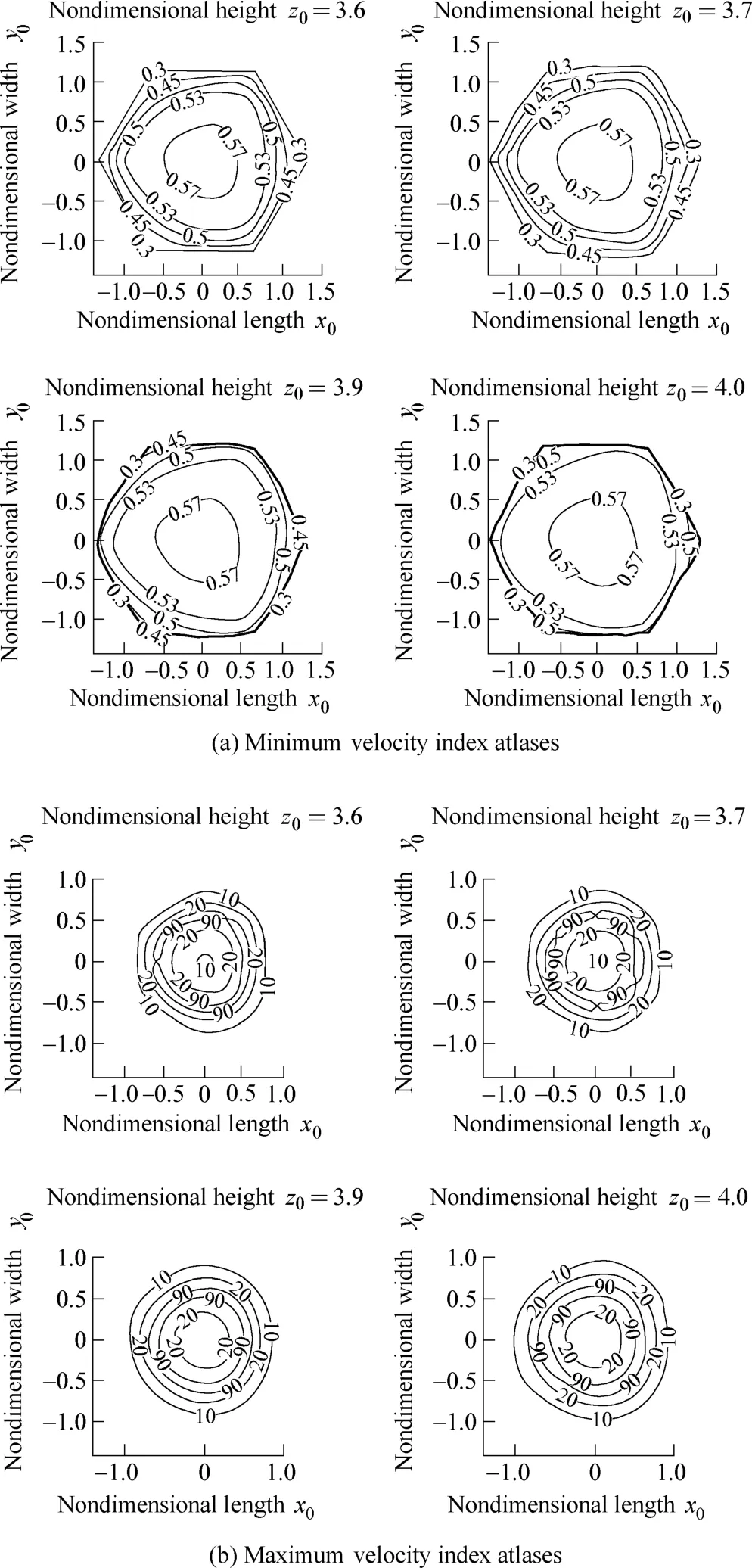
Fig. 7. Atlases of the payload capability index of the 3-RPUR PM
4.6 Stiffness analysis
The relationship between the deformation D of the end actuator and the general force vector F applied to the mechanism can be expressed as

where C is the flexibility matrix, and
According to Eqs. (10), (11) and (28), the stiffness index atlases of the 3-RPUR PM are plotted and shown in Fig. 8.
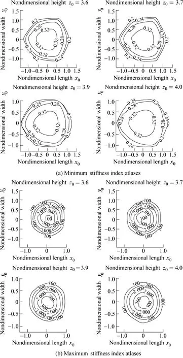
Fig. 8. Atlases of the stiffness index of 3-PRUR PM
The maximum or minimum deformation obtained from Eq. (28) only reflects the deformation situations of the mechanism in a certain position, then to evaluate the stiffness performance of the mechanism in the whole workspace, the global stiffness indices are defined as follows[21]:
where ςDmaxand ςDminare the maximum and minimum global stiffness indices, respectively; W denotes the workspace of the mechanism.
Then the maximum and minimum global stiffness indices of the 3-RPUR PM in the whole workspace can be solved, which are equal to 1 228.5 and 0.300 38,respectively. The maximum and minimum global stiffness indices of the 3-CPR PM are both equivalent to 1.
From the above analysis, it can be seen that the maximum global stiffness index of the 3-RPUR PM is far bigger than that of the 3-CPR PM, while the minimum global stiffness index of the 3-RPUR PM is smaller than that of the 3-CPR PM. This indicates that the coupled 3-RPUR PM is more suitable for the application requiring large stiffness in some directions.
5 Conclusions
(1) Taking the 3-RPUR PM and the 3-CPR PM as example, the comparative analysis of characteristics of the coupled and decoupled PMs, including the kinematics,workspace, dexterity, velocity, payload capability and stiffness, has been performed.
(2) Compared with the coupled PM, the Jacobian matrix of the DPM is a constant matrix, which is independent of the pose of the mechanism. The condition number of the Jacobian matrix is equal to 1, and the mechanism possesses excellent force and motion transmission capabilities.
(3) Both the forward and the inverse displacement solutions of the DPM are straightforward and almost do not need to calculate. The shape of the workspace of the DPM is regular, and it is free from singularities in the whole workspace.
(4) The velocity, payload capability and stiffness indices of the coupled PM are better than that of the DPM in some directions. While the performance indices of the DPM,including dexterity, velocity, payload capability and stiffness, keep invariable in the workspace.
(5) The higher the decoupling extent of the PM is, the easier the kinematics and dynamics analysis are, which is more favorable for the control and the improvement of the movement precision.
(6) The coupled and decoupled PMs have their own advantages and disadvantages, and which one is more suitable for a certain application should depend on the specific situation.
[1] PATARINSKI S P, UCHIYAMA M. Position/orientation decoupled parallel manipulator[C]//Proceedings of International Conference on Advanced Robotics, Tokyo, Japan, 1993: 153–158.
[2] INNOCENTI C, PARENTI-CASTELLI V. Direct kinematics of the 6–4 fully parallel manipulator with position and orientation uncoupled[C]//Proceedings of the European Robotics and Intelligent Systems, Corfou, 1991: 23–28.
[3] RYU D, CHO C, KIM M, et al. Design of a 6 DOF haptic master for teleoperation of a mobile manipulator[C]//Proceedings of IEEE International Conference on Robotics and Automation, Taipei,China, 2003: 3 243–3 248.
[4] HUANG Zhen, LI Qinchuan. 3-DOF translational parallel robot mechanism: China, 01104454.3[P]. 2001-09-05.
[5] CARRICATO M, PARENTI-CASTELLI V. Singularity-free fully-isotropic translational parallel mechanisms[J]. The International Journal of Robotics Research, 2002, 21(2): 161–174.
[6] CARRICATO M, PARENTI-CASTELLI V. A novel fully decoupled two-degrees-of-freedom parallel wrist[J]. The International Journal of Robotics Research, 2004, 23(6): 661–667.
[7] KONG Xianwen, GOSSELIN C M. Kinematics and singularity analysis of a novel type of 3-CRR 3-DOF translational parallel manipulator[J]. The International Journal of Robotics Research,2002, 21(9): 791–798.
[8] KONG Xianwen, GOSSELIN C M. Type synthesis of input-output decoupled parallel manipulators[J]. Transactions of the Canadian Society for Mechanical Engineering, 2004, 28(2): 185–196.
[9] KIM H S, TSAI L W. Design optimization of a Cartesian parallel manipulator[C]//Proceedings of the ASME Design Engineering Technical Conference, Montreal, Quebec, Canada, September 29,2002, 5B: 865–872.
[10] LI Weimin, GAO Feng, ZHANG Jianjun. R-CUBE, a decoupled parallel manipulator only with revolute joints[J]. Mechanism and Machine Theory, 2005, 40(4): 467–473.
[11] GOGU G. Fully-isotropic over-constrained parallel wrists with two degrees of freedom[C]//Proceedings of the 2005 IEEE International Conference on Robotics and Automation, Barcelona, Spain, 2005:4 025–4 030.
[12] HUANG Zhen, ZHAO Yongsheng, ZHAO Tieshi. Advanced spatial mechanism[M]. Beijing: Higher Education Press, 2006. (in Chinese)
[13] DAVIES T H, BAKER J E, THOMPSON A G R. A finite,3-dimensional atlas of 4-bar linkages[J]. Mechanism and Machine Theory, 1979, 14(6): 389–403.
[14] BARKER C R, WEEKS G A. A physical model of the solution space for four bar mechanisms[C]//Proceedings-OSU Applied Mechanism Conference, St Louis, MO, USA, 1983: 26–33.
[15] YANG Jihou. The space model and dimensional types of the four-bar mechanisms[J]. Mechanism and Machine Theory, 1987,22(1): 71–76.
[16] POND G, CARRETERO J A. Formulating Jacobian matrices for the dexterity analysis of parallel manipulators[J]. Mechanism and Machine Theory, 2006, 41(12): 1 505–1 519.
[17] SALISBURY J K, CRAIG J J. Articulated hands: force control and kinematic issues[J]. The International Journal of Robotics Research,1982, 1(1): 4–17.
[18] GOSSELIN C M, ANGELES J. A global performance index for the kinematic optimization of robotic manipulators[J]. Journal of Mechanical Design, 1991, 113(3): 220–226.
[19] GAO Feng, LIU Xinjun, GRUVER W A. Performance evaluation of two-degree-of-freedom planar parallel robots[J]. Mechanism and Machine Theory, 1998, 33(6): 661–668.
[20] LIU Xinjun, WANG Jinsong, PRITSCHOW G. Performance atlases and optimum design of planar 5R symmetrical parallel mechanisms[J]. Mechanism and Machine Theory, 2006, 41(2):119–144.
[21] LIU Xinjun, JIN Zhenlin, GAO Feng. Optimum design of 3-DOF spherical parallel manipulators with respect to the conditioning and stiffness indices[J]. Mechanism and Machine Theory, 2000, 35(9):1 257–1 267.
杂志排行

Chinese Journal of Mechanical Engineering的其它文章
- Dynamic Manipulability and Optimization of a Two DOF Parallel Mechanism
- Design of Robot Welding Seam Tracking System with Structured Light Vision
- New Method to Measure the Fill Level of the Ball Mill I—Theoretical Analysis and DEM Simulation
- New Hybrid Parallel Algorithm for Variable-sized Batch Splitting Scheduling with Alternative Machines in Job Shops
- Multidisciplinary Design Optimization with a New Effective Method
- Reliability Analysis of Electromechanical Systems with Degraded Components Containing Multiple Performance Parameters