Design of Robot Welding Seam Tracking System with Structured Light Vision
2010-03-01LIUSuyiWANGGuorongZHANGHuaandJIAJianping
LIU Suyi, WANG Guorong, ZHANG Hua, and JIA Jianping
1 Provincial Key Lab of Robot and Weld Automation, Nanchang University, Nanchang 330031, China
2 School of Mechanical and Automotive Engineering, South China University of Technology,Guangzhou 510640, China
1 Introduction
Welding production is developing to automatization and robotization[1,2]. And automatic seam tracking is one of important problems in robot welding[3,4]. In robot automatic and intelligent welding, it is very important to develop and apply seam tracking system. At the same time, sensors play very important role in seam tracking and they affect directly seam tracking precision[5].
There are many kinds of sensors used for seam tracking,among which arc sensors and vision sensors are widely used. Arc sensors are mainly applicable to the welding joint with symmetrical sides, while vision sensors are not restricted to welding joint types and welding material and they can get much information. Therefore, vision sensors have become research focus in automatic and intelligent welding system[6,7].
Generally, according to using auxiliary light sources or not, seam tracking vision is divided into two kinds: active vision and passive vision. Research show that passive vision has low signal noise ratio since no auxiliary light is used. So, active vision is widely used in seam tracking.
As laser has advantages of good homochromy, strong orientation, concentrated energy density, and so on, seam images with high signal noise ratio can be obtained by using laser as auxiliary light sources, and the shape,position and dimensions of welding joint can be obtained more easily. So many researchers in the world pay much attention to structured light vision. In some developed countries, e.g. England, Canada, Sweden, and so on, seam tracking merchant products with structured light vision have already come out. But they are often very expensive and can only be applied on special occasions. In China the research of structured light vision seam tracking system is basically just on the stage of experiments.
In this paper, a robot seam tracking system with structured light vision is studied by using Meta laser sensor and IRB1400 robot. The robot seam tracking system includes a line structured light vision and images acquisition, seam images recognition and extraction,system coordinates calibration and transform,communication between PC and robot, robot seam tracking control, etc. In order to obtain accurate seam positions,image filtering and image recognition was studied. A filtering method and two kinds of image recognition for laser seam images were improved, two kinds of image recognition were proposed, and for precise seam position coordinates and decreasing calibrating time, a simultaneous calibration for camera parameters and robot hand-eye were also proposed. Robot seam tracking experiments were conducted with line seam and folded seam for lap-joint to evaluate the effectiveness of the improved methods, the proposed methods, and the whole system.
2 Makeup and Principle of Seam Tracking System
The hardware of seam tracking system mainly comprises structured light vision sensor, arc welding robot, image capturing card, PC, welding equipment, and so on. The framework of the whole system is shown in Fig. 1.
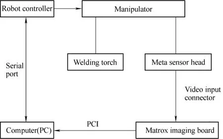
Fig. 1. Block diagram for robot seam tracking system
A Meta laser sensor is fixed on the end of robot manipulator and is 60 mm in front of welding torch,sensing the seam to be welded. The system software is divided into such modules as seam images acquisition,image recognition and extraction, communication between PC and robot, PC control, robot control. Before seam tracking, the values of welding parameters such as welding speed, welding joint type, start position and end position,are to be set on software interface. During welding, the images of seam to be welded through filter plates are captured by CCD camera, and then are passed to image acquisition card in PC. They are captured every 100 ms according to the setting time in the PC control program. In succession, the program module of seam image processing and recognition extract the coordinates of seam center and then they are transformed to space coordinates by sub-module program in PC control program. After the space coordinates of seam center is sent to robot by the communication program module, robot control program gives instructions to control the motion of manipulator according to the received coordinates. Sequentially,welding torch is brought to reach the next seam position to the present one, achieving robot seam tracking.
3 Recognition and Extraction of Laser Seam Images
As there are different kinds of disturbances such as arc light, smoke and dust, spatter, and so on in arc welding,many noises are included in initial seam images captured by vision system and the signal noise ratio is low. How to precisely recognize and extract coordinates of seam center from initial images is a key process, since the DSP system of Meta laser sensor can not recognize and extract seam center during tracking.
3.1 Acquisition of laser seam images
Fig. 2 is the sketch of robot seam tracking with line structured light vision. Fig. 3 is laser images for lap joint captured during welding. In experiments, the type of welding wire is flux cored wire SQJ501 made in Tianjing Sainteagle Welding Company of China and welding parameters are shown in Table 1.
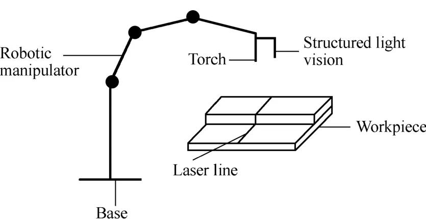
Fig. 2. Sketch of robot seam tracking with structured light vision
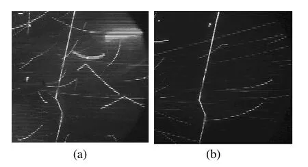
Fig. 3. Welding laser images for lap-joint
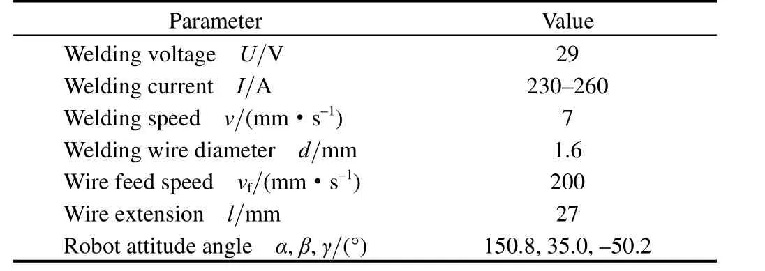
Table 1. Welding parameters of lap-joint
3.2 Images recognition and extraction
It is the first step to recognize and extract the seam position in seam tracking with vision sensing. In laser seam images, the seam position to be extracted is different to different types of welding joint. For butt v-joint, the seam position is on the peak of v-angle in laser line, while for lap-joint the seam position is corresponding to the first turning in laser line which is shown in Fig. 4 and P is the image position of seam center. Seen from Fig. 3, there are many white line spatter noise, some arc light noise, and some smoke and dust noise. Such noises seriously interference the recognition and extraction of seam center.So image filtering is necessary.
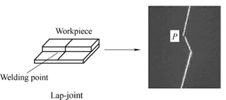
Fig. 4. Seam position for lap-joint
3.2.1 Images filtering
Image filtering methods in common use are average filtering, median filtering, etc. But average filtering is just able to remove a small part of noise. In median filtering,image processing effect is better with square window than with level window or vertical window, and the bigger the square window is, the better the effect is, but the worse the real time is, what’s more, the more blurry the seam feature in images is. So, an image filtering is developed in this paper.
From observation, the gray value of background in structured light vision seam images is generally below 50 and the gray value of noise and laser line is basically over 100. The width of laser line is about 2–3 pixels and the noise is most linear and dot, and its width is most above 4 pixels. On the basis of these characteristics, a filtering method is studied as follows:
(1) Choose a level window of 1× 5 pixels size in images and select a certain threshold value T.
(2) When the gray value of the first pixel in the 1× 5 pixels level window is less than T and the other four pixels are larger than T, the four pixels are regarded as noise and substitute the first pixel for the other four pixels.
(3) Scan the whole image in terms of the above rules.
As the noise is different in every captured seam image,the threshold value T is not all the same and whether T is appropriate or not will directly affect the results of image processing. Therefore, a probability average gray value is determined according to the following formula through counting the pixel numbers whose gray value is between 50 and 100:
Where, i is gray level ( i= 50 −1 00 ), niis the pixel number of gray i.
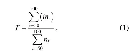
Fig. 5(a) is filtering result of Fig. 3(a) using the above method and 3×3 median filtering; Fig. 5(b) and Fig. 5(c)are respectively the median filtering results of Fig. 3(a)with 3× 3 pixels window and 5×5 pixels window directly.
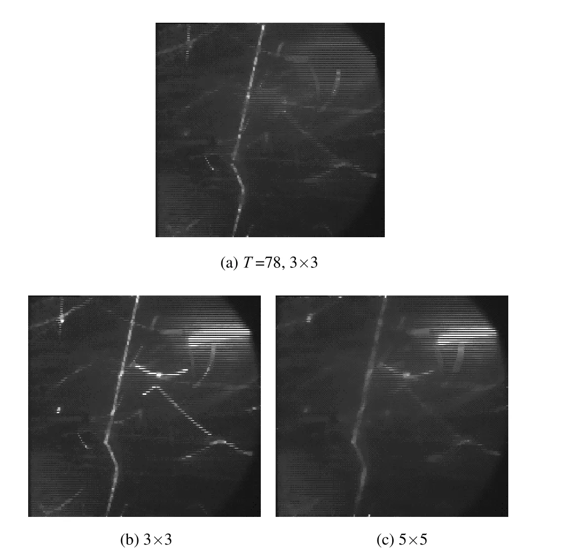
Fig. 5. Filtering result for improved method and median filtering
The comparative result of Fig. 5 shows that the improved filtering effect with 3× 3 pixels window is better than median filtering with 5×5 pixels window. Moreover, the improved method has good real time.
3.2.2 Image binarizing
As the arc is unstable during welding, the background gray value in seam images is not constant. A gray threshold value which leads to good effect in one picture, may not have good effect on other pictures. In view of this problem,a method to self-adaptively adjust threshold, the maximum variance of the threshold[8,9], is used to computing the binarizing gray value and Fig. 6 is the binarizing images.
Fig. 6. Binarizing images
3.2.3 Image thinning
In order to decrease image noise further and recognize and extract precisely the seam center, thinning processing is performed to binarizing image. Thinning method is to match the binary image in turn with structure elements
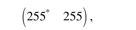
and
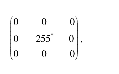
when a pixel accords with one of the two structures, its gray value is set to 0 (the pixel marked with * is presently matched one). Fig. 7 shows the result of this thinning processing.
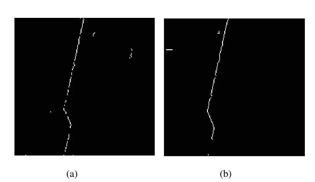
Fig. 7. Thinning images
3.2.4 Seam center recognition and extraction
There are different ways to recognize and extract seam center of lap-joint (the P point in Fig. 4) from Fig. 7. Four methods are studied in this paper: structure element matching, fast template matching, fast Hough transforming,and corner detecting[10]. Image recognizing experiments show that, the four recognition methods can all extract the seam center of lap-joint, and therein structure element matching is less stable while fast template matching and corner detecting do better in denoising and have higher validity, and what’s more, corner detecting is more real-time. Finally, the extracted seam positions in Fig. 7 are respectively (67,126) and (66,128).
4 Coordinates Calibration and Transforming
From the above section, the image position of seam center is extracted. The next step is to determine the space position of next welding point by the extracted seam center and it needs to make coordinates transforming, that is,turning the image position of seam center to space coordinates in robot base system.
4.1 Relations of coordinates frames
Suppose, a point in image plane is denoted by, and a point in world frame is denoted byTheir homogeneous coordinates areandThen according to the optical principle of camera Pin-hole model, the following transformation between image frame and world frame is set up[11,12]:
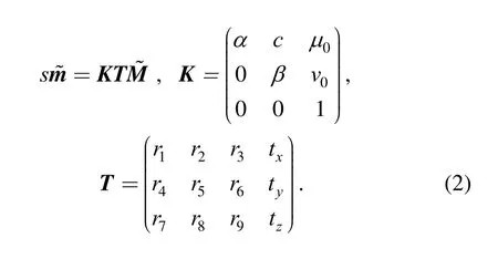
Where s is an arbitrary scale factor, K is the camera intrinsic parameter matrix in which (u0,0v) is the coordinates of camera principal point, α and β are the scale factors in x and y axes, and c denotes the skewness of two image axes, and T is the camera extrinsic parameter matrix in whichare the rotation part of the camera frame to the world frame andthe translation part.
And suppose H is the transformation matrix of robot hand frame to the camera frame,6T the robot hand frame to robot base frame, and R the camera frame to robot base frame. The relations of this three transformation matrixes is as Fig. 8. It is obvious that the relation of these three matrices can be expressed as
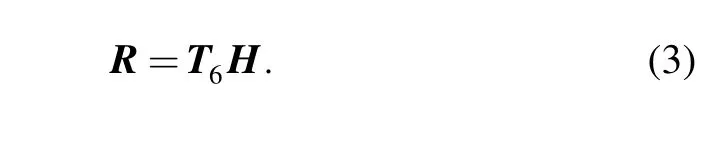
Here, the world frame is defined as robot base frame, so the following equation can be educed:
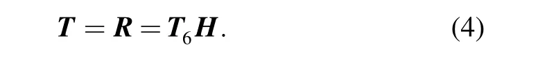
Therein, T is the same in Eq. (2) and the following is obtained:
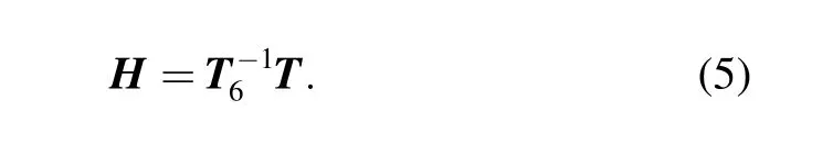
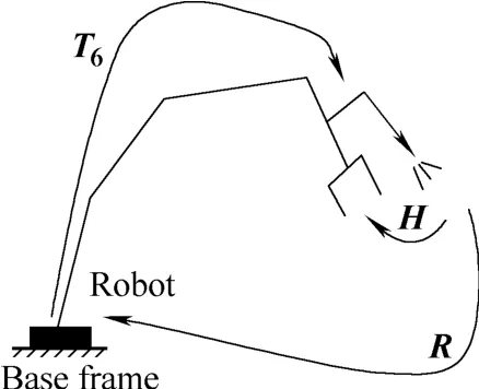
Fig. 8. Matrix relations
4.2 Solution for calibration parameters
According to the orthogonality of the rotation part in Eq.(2) and selecting over 6 calibration control points, 18 nonlinear equations are set up to solve the 17 unknown parameters in Eq. (2). Actually, this is an optimization problem with nonlinear least squares[13]. The optimization initial values of the unknown parameters are chosen as following:
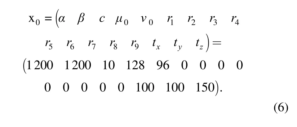
Levenberg-Marquardt method is applied to solve the nonlinear equations, and then matrix H is solved out by Eq. (5). The final computing results are listed in the following:
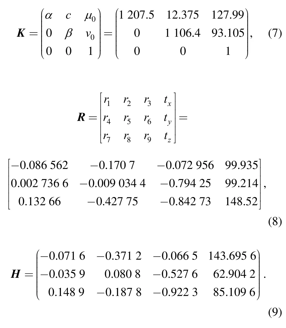
Where K and H are fixed, and R varies with different positions of camera.
4.3 Calibration transformation
From the above solution, in structured light vision the camera parameter matrix K and T, and robot hand-eye matrix H are determined. Such, the coordinates of every point in a seam in robot base frame can be transformed from its corresponding image coordinates[14].
Suppose that (x, y) is the image coordinate of a point on a seam. Its 3D coordinate in camera frame isand its coordinate in robot base frame is
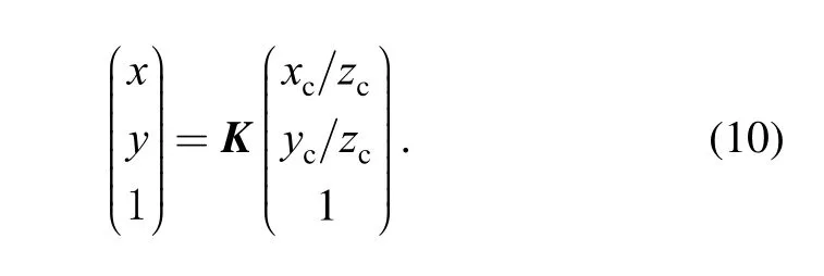
Then by the camera internal parameters matrix K, the transformation between image coordinates and camera frame coordinates is given in the following:
The transformation between camera frame coordinates and robot base frame is
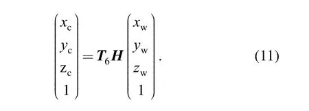
Generally, reconstructing space 3D coordinates of a point needs two images at least. But when the robot tracks seam on a plane, zwof a seam is constant. So in the condition that zwis known, robot base frame coordinates of points in a seam are solved out by combining Eqs. (10) and (11).
5 Communication Between PC and Robot
There are two modes to communicate between computer and robot: one is to use computer network and the other is by serial port communication (SPC). In view of practical application requirements in this paper, RS232C SPC mode is employed.
5.1 Communication protocol
In robot seam tracking system, the communication between PC and robot is used to transmit some control commands and data, and its detail tasks are the following.
(1) PC sends the information to robot, which includes command words for robot motion mode such as manual mode or tracking mode, coordinates for next point in seam,and robot movement speed.
(2) PC receives the information from robot, which is the current coordinate of welding torch and command words to notify PC to capture next seam image.
5.2 SPC programming
Commonly, there are three ways to realize SPC with Visual C++ in Windows environment: MSComm ActiveX,WinAPI communication functions, and CSerialPort Class.The three ways have their advantages and disadvantages respectively, and CSerialPort class is used to realize SPC in the paper. Baud rate is set to 19 200 bit/s.
6 Robot Seam Tracking Control
The seam tracking control in this paper is substantially the process control of robot successive motion along a seam line. The tracking method is to evenly divide a seam line into some small segments, and the welding torch successively moves along every small segment. In this way,a folded line comprised of these small segments approximates to the real seam line, which is shown in Fig.9. The length of every small segment is equal and depends on the distance between welding torch and the current sensing seam center. In order to make robot move more smoothly, every segmentis again divided into many smaller segments, e.g. 20 to 30 ones. The successive motion of welding torch along a seam is controlled in harmony by robot program and PC program.
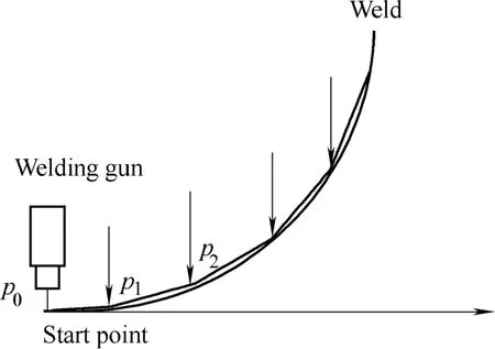
Fig. 9. Sketch for robot seam tracking
7 Experiments
Two groups of robot seam tracking experiments for lap-joint are made with flux cored wire (SQJ501 made in Tianjing Sainteagle Company of China). First a linear seam is tracked, and then a folded seam is tracked.
7.1 Linear seam tracking for different image recognitions
In this group, on the basically same situation of welding conditions, four seam recognition methods, i.e. structure element matching, fast template matching, fast Hough transforming, and corner detecting, are used respectively to track linear seam for lap-joint. Fig. 10 is the experiment result and Table 2 lists the experiment parameters.
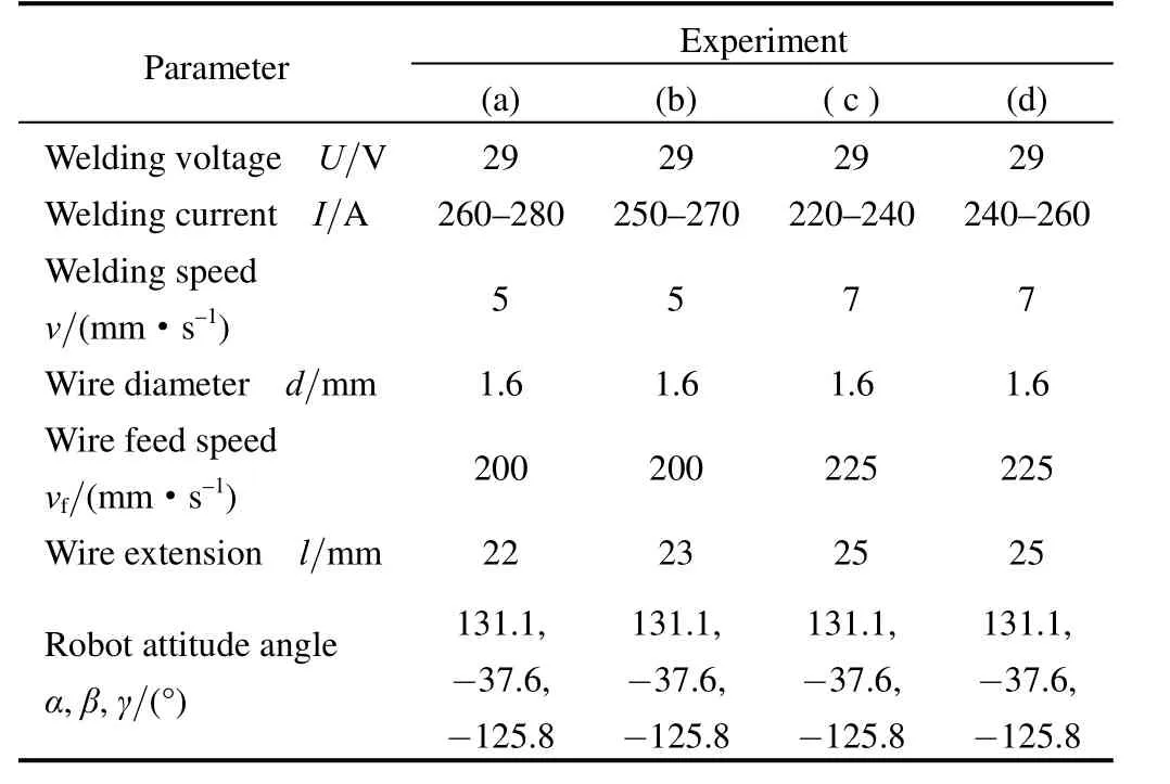
Table 2. Welding parameters for linear seam tracking
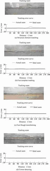
Fig. 10. Linear seam experiment results for lap-joint with different image recognitions
7.2 Folded seam tracking experiments
For further testing the seam tracking system, in this group of experiments, corner detecting, which is more stable and is better in real time, is applied to track folded seams. Fig. 11 shows the results and Table 3 is its corresponding experiment conditions.
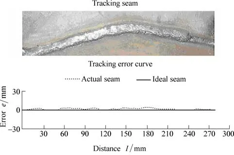
Fig. 11. Folded seam experiment results for lap-joint with corner detecting
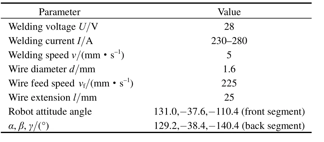
Table 3. Welding parameters for folded seam tracking
8 Conclusions
(1) Structured light vision is effective to obtain seam feature information, and is applicable to different types of welding joint.
(2) The four seam recognitions for lap-joint can all recognize and extract image positions of seam center momentarily and effectively. Among them, fast template matching, fast Hough transforming, and corner detecting can get smooth tracking seams, while structure element matching is less stable than others and gets tracking seam with some fluctuations.
(3) The effect of folded seam tracking experiment is satisfied by using corner detecting to recognize seam position and it is stable and good real time.
(4) The system studied can realize the requirements of real-time robot seam tracking with structured light vision and the experiment results are satisfying for lap-joint.
[1] LIN Shangyang, GUAN Qiao. Study on welding production conditions and developing strategy in our country’s manufacture[J].Mechanical worker (Hot machining), 2004 (8): 16–20. (in Chinese)
[2] LIN Shangyang. China is forging ahead from large welding country toward strong welding country in the world—some problems about welding product & development in our country[J]. Aeronautical Manufacturing Technology, 2002 (11): 17–19, 44. (in Chinese)
[3] LIN Shangyang, CHEN Shangben, LI Chengtong. Welding robot and application[M]. Beijing: China Machine Press, 2000. (in Chinese)
[4] PAN Jiluan. Modern arc welding control[M]. Beijing: China Machine Press, 2000. (in Chinese)
[5] HU Shenggang, LI Junyue, PEI Xuemei. Developing status and their control technique for optical arc welding sensors [J]. Welded Pipe and Tube, 1998, 21(1): 10–19. (in Chinese)
[6] BOB Irving. Sensors and controls continue to close the loop in arc welding[J]. Welding Journal, 1999, 4: 31–36.
[7] LIU Suyi, WANG Guorong, ZHONG Jiguang. Application and prospect of vision sensing system in robot welding[J]. Mechanical Science and Technology, 2005, 24(11): 1 296–1 300. (in Chinese)
[8] FAN Xinnan, GUO Jianjia. Self-adaptive threshold segmentation algorithm about engineering images[J]. Computer Measurement &Control, 2006, 14(3): 395–397.
[9] XUE Lanyan, CHENG Li. Image segmentation based on the method of the maximal variance and the improved genetic algorithm[J].Computer Applications and Software, 2008, 25(2): 221–222, 247. (in Chinese)
[10] LIU Suyi. Research on groove image processing and robot seam tracking system[D]. Guangzhou: South China University of Technology, 2006. (in Chinese)
[11] ZHANG Zhengyou. Camera calibration with one-dimensional objects[J]. IEEE Transactionson Pattern Analysis and Machine Intelligence, 2004, 26(7): 892–899.
[12] LUO Honggen, ZHU Liming, DING Han. Camera calibration with coplanar calibration board near parallel to the imaging plane[J].Sensors and Actuators A, 2006, 132(2): 480–486.
[13] XU Chengxian, CHEN Zhiping, LI Naicheng. Modern optimization[M]. Beijing: Science Press, 2002. (in Chinese)
[14] LIU Suyi, WANG Guorong, SHI Yonghua. Simultaneous calibration of camera and hand-eye in robot welding with laser vision[J].Journal of South China University of Technology(Natural Science Edition), 2008, 36(2): 74–77, 82. (in Chinese)
杂志排行

Chinese Journal of Mechanical Engineering的其它文章
- Dynamic Manipulability and Optimization of a Two DOF Parallel Mechanism
- New Method to Measure the Fill Level of the Ball Mill I—Theoretical Analysis and DEM Simulation
- Comparative Analysis of Characteristics of the Coupled and Decoupled Parallel Mechanisms
- New Hybrid Parallel Algorithm for Variable-sized Batch Splitting Scheduling with Alternative Machines in Job Shops
- Multidisciplinary Design Optimization with a New Effective Method
- Reliability Analysis of Electromechanical Systems with Degraded Components Containing Multiple Performance Parameters