Progress of Lyman-alpha-based beam emission spectroscopy (LyBES) diagnostic on the HL-2A tokamak
2024-04-06YixuanZHOU周艺轩YiYU余羿MinXU许敏RuiKE柯锐LinNIE聂林HaoXU徐皓GuangyiZHAO赵光义HaoLIU刘灏ZihaoYUAN袁子豪ChenyuXIAO肖晨雨JiquanLI李继全ChijieXIAO肖池阶andtheHL2ATeam
Yixuan ZHOU (周艺轩) ,Yi YU (余羿) ,Min XU (许敏) ,Rui KE (柯锐) ,Lin NIE (聂林) ,Hao XU (徐皓),2 ,Guangyi ZHAO (赵光义),Hao LIU (刘灏),Zihao YUAN (袁子豪),Chenyu XIAO (肖晨雨),Jiquan LI (李继全),Chijie XIAO (肖池阶) and the HL-2A Team
1 Southwestern Institute of Physics,Chengdu 610041,People’s Republic of China
2 Sino-French Institute of Nuclear Engineering and Technology,Sun Yat-sen University,Zhuhai 519082,People’s Republic of China
3 State Key Laboratory of Nuclear Physics and Technology,School of Physics,Peking University,Beijing 100871,People’s Republic of China
Abstract An edge Lyman-alpha-based beam emission spectroscopy (LyBES) diagnostic,using a heating NBI (neutral beam injection) system,is currently under development on the HL-2A tokamak.The 20-channel edge LyBES,which is intended to measure the density fluctuation in plasma edge (from R=1960 mm to R=2026 mm) with an improved spatial resolution of 3.3 mm,is a complement to the existing conventional beam emission spectroscopy (BES) diagnostic.In this article,we introduce the progress of LyBES diagnostic,including the collection optics,the monochromator,and the detector system.The reflectance of the collection mirrors is measured to be~82% at 122 nm,and the aberration geometrical radius of the collection optics is tested to be~150 μm in the aimed area.The linear dispersion of the LyBES monochromator is designed to be~0.09 nm mm-1.The bandwidth of the detector system with the 5×10⁷ V A-1 preamplifier gain is measured to be~280 kHz,and the peak-to-peak noise of the detector system is tested to be~16 mV.The finalized design,components development and testing of the LyBES diagnostic have been completed at present,and an overall performance of the LyBES diagnostic is to be confirmed in the next HL-2A campaign.
Keywords: density fluctuation,LyBES,BES,vacuum ultraviolet
1.Introduction
The anomalous transport phenomenon [1,2],i.e.transport is greatly higher than that predicted by classical or neoclassical theory,is one of the key scientific challenges in fusion plasma physics research.Previous studies suggest that the anomalous transport is driven by turbulent fluctuations,which is characterized as non-linear and occurs over multiple scales in time and space [3].
In order to investigate anomalous transport,L-H transitions,and other turbulent-related phenomena,a variety of different diagnostics were developed on fusion devices,including ultrafast charge exchange recombination spectroscopy [4],electron cyclotron emission imaging [5],gas puffing imaging [6],etc.Beam emission spectroscopy(BES),which has been widely deployed in many tokamaks[7-12],is a powerful tool for turbulence investigation with high temporal and spatial resolutions.Currently,a 48-channel visible light BES diagnostic [13,14] has been developed on the HL-2A tokamak for the measurement of two-dimension density fluctuations.This visible light BES system has one of the best spatial resolutions reported worldwide[7-14],which is about 0.8 cm (radial) × 1.2 cm (poloidal)and has been applied to the research of transport barrier,edge-localized modes (ELM),magneto-hydrodynamic(MHD) instabilities,etc.
Although the 1μs temporal resolution of the visible light BES could meet the requirement of turbulent measurement on HL-2A,the BES spatial resolution is limited by the time constant [15] of the detected spectral line (Balmer-alpha,656.10 nm),and cannot be further enhanced.Therefore,the visible light BES system does not have adequate capacity for research at the smallest spatial and temporal scales,such as the analysis of ELM and edge coherent oscillation (ECO) in the pedestal area on HL-2A [14].For the purpose of improving the performance of beam emission spectroscopy,the idea of Lyman-alpha-based BES (LyBES) was proposed theoretically twenty years ago [16].Compared with the conventional visible light BES diagnostic,LyBES could have a theoretically improved spatial resolution of several millimeters while maintaining the temporal resolution of 1μs,which results mainly from the short lifetime of the Lyman-alpha line (n=2→1,λ0=121.53 nm).Furthermore,LyBES could have greater signal intensity than that of visible light BES,benefited from a larger transition rate,state density,and fluctuation sensitivity of the Lyman-alpha line [16-18].However,there is no further progress reported on LyBES,probably owing to the greater technical and engineering difficulties of vacuum ultraviolet spectroscopy.In recent years,for the first time,a novel edge LyBES system has been developed for the HL-2A tokamak,and the detailed calculations and design of LyBES have been completed [17,18].It is to be noted that the LyBES was called LAB previously [17,18],which refers to the same diagnostic.
In this article,the recent progress of LyBES diagnostic on HL-2A is presented.The engineering design of the LyBES system was further perfected.The main components have been fabricated and the performance testing of these components has been performed in the simulated laboratory circumstance which is similar to HL-2A plasma,including the reflection-type collection optics,the vacuum ultraviolet(VUV) monochromator,and the high gain detector system.The testing results show that all LyBES components achieved the anticipated requirements in the design stage.The overall performance of the LyBES diagnostic is to be further analyzed on the HL-2A tokamak in our next step.
The rest of this article is arranged as follows.In section 2,the LyBES diagnostic system on HL-2A is briefly described and the detailed performance testing of LyBES is presented in section 3.In section 4,a brief summary is given.
2.The LyBES diagnostic system on HL-2A
HL-2A is a medium-sized tokamak with a major radius ofR0=1.65 m and a minor radius ofa=0.4 m.The toroidal magnetic field can be operated fromBt=1.2 T to 2.7 T and the plasma current can be operated fromIp=150 kA to 480 kA.The auxiliary heating of HL-2A includes two tangential neutral beam injection (NBI,1.5 MW/45 keV) systems.
During the collisional interaction process between the injected neutral atoms of NBI and the fusion plasma,different kinds of light emitted from the radiative decay of atomic transitions will be collected to obtain the information of plasma.Exactly the same as conventional BES,LyBES detects the Doppler-shifted monochromic characteristic line which is emitted by the de-excitation of excited deuterium atoms,to infer electron density fluctuation.Compared with the Doppler-shifted Balmer-alpha line (n=3→2,λ0=656.10 nm) collected by conventional BES,LyBES observes the Doppler-shifted Lyman-alpha line (n=2→1,λ0=121.53 nm) which lies in the vacuum ultraviolet band.The wavelength of the targeted Doppler-shifted Lyman-alpha line is~121.98 nm on HL-2A [17,18],with the chosen line of sight.The viewing area of the developing LyBES system on HL-2A will cover plasma fromR=1960 mm toR=2026 mm,with an average spatial resolution of 3.3 mm.
Besides the relative advantages of improved spatial resolution and higher signal intensity [16-18],there are many technical,engineering,and practical difficulties of the novel LyBES on HL-2A,including but not limited to:
(1) Presently,optical and detecting elements applied in vacuum ultraviolet band are lacking of high performance and efficiency.Particularly,there is no available optical filter with suitable spectral bandwidth and efficiency in the working wavelength of LyBES,which is the general component of conventional BES.In fact,many devices (Alcator C-Mod,TCV,LTX,DIII-D,etc.) have utilized Lyman-alpha filtered detectors [19-23],but the minimum filter width (~5 nm FWHM) is too large to be applied for LyBES (~0.45 nm doppler-shift).Here,FWHM refers to full width at half maximum.
(2) In order to detect the monochromatic Doppler-shifted Lyman-alpha line,and filter out the background spectral lines,the spectral resolution ability with a subnanometer accuracy is required for LyBES.Combined with the demand for high throughput,LyBES needs large-size optical elements with surface profiles of high precision.Besides,the LyBES system is cumbersome.Moreover,the optical fiber cannot be used in the LyBES system for the coupling of components.All these requirements of LyBES make it much more difficult for optical adjusting and alignment.
(3) One unfavorable weakness of LyBES resulting from the improved spatial resolution is the decreased optical throughput.Therefore,the overall efficiency should be optimized as much as possible,in the aspect of system design and components development.
(4) The limited,irregular space that could be utilized for LyBES on HL-2A and the technical requirement of full vacuum further add to the engineering difficulty.
(5) The electromagnetic environment is quite complex and harsh,because of the short distance between the LyBES system and HL-2A tokamak.
3.Performance testing of LyBES
3.1.Collection optics
For the purpose of collecting and imaging the fluorescence emitted from the observing area with required magnification and image quality,the reflection-type telescope system is designed and developed.A detailed description of the optical path and parameters can be found in our previous works[17,18].On the basis of satisfying the functional requirements of LyBES,the designed collection optics should have a high light-receiving efficiency and a low optical aberration.
So as to fix and support the collecting mirrors to the given position and angle,the mechanical structure of the LyBES collection optics was designed.Actually,two versions of the mechanical structure were designed.Version one is the unadjustable structure with a high installation and machining accuracy,as shown in figure 1.Version two is the adjustable structure,which could have a better image quality by modest adjustment manually.Version two will be utilized only if the image quality of version one could not satisfy the demands,considering that version two would be less stable than version one even with the locked solid structure.According to the testing results,version one is ultimately adopted.
The collecting optics is simply composed of three mirrors,intending to maximize the efficiency performance,as illustrated in figure 2 .The primary mirror and the secondary mirror are all aspheric surfaces,and the diameter of the primary mirror is as large as 180 mm,which is one of the largest first mirrors for BES as reported worldwide.The plane mirror is added to bend the light ray,due to the limited space for transmission.
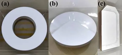
Figure 2.Photographs of the collection mirrors.(a) Primary mirror,(b) secondary mirror,(c) plane mirror.
The primary mirror is precisely fastened and locked by the first base and the body tube.The external diameter of the body tube is 190 mm,with a thickness of 7 mm in the central area and 4 mm on the two sides.The material of the mechanical structure is completely 316L stainless steel,with a relative permeability of lower than 1.04.The secondary mirror is firstly fixed on the holder and then rotated into the body tube along the densely covered screw thread.The secondary mirror is fastened and locked by the stair on the body tube and the clamp.The plane mirror is placed on the second base and is locked by three pressing blocks.Parts of the unused region of the plane mirror are cut for assembling,as shown in figure 2(c).In addition,there are four fixtures designed for the connection of the collection optical system and the flange of HL-2A,as indicated in figure 3.Once installed on HL-2A,a shutter in front of the collection optical system is needed for the protection of mirrors.The support for the installation and anchoring of the shutter has been reserved.The shutter is driven by gear,which is confirmed to be stable and reliable on HL-2A.The overall mechanical structure of the LyBES collection optics was specially optimized,in order to avoid interference with the flange on HL-2A and other diagnostic systems.The mechanical structure of the LyBES collection optics could have enough strength and constancy for optical imaging and meets the requirements of the HL-2A online experiment simultaneously.
The principal reason for the utilization of reflecting mirrors in the LyBES system is that there is no lens material with sufficient transmittance at 121.98 nm presently.In order to obtain high-performance reflective coatings at 121.98 nm,studies on the fabrication technology and the relevant physical mechanisms of fluoride protected aluminum-based reflective coatings were carried out by collaborating with another Chinese scientific research institution.The designed and measured results for the reflectance of LyBES collection mirrors are shown in figure 3.The 0° and 60° in figure 3 are the angles of incidence (AOI) for the primary/secondary mirror and the plane mirror,respectively.It is noted here that the design and implementation of coatings for different AOI are conducted individually,intending to furthest improve the reflectance.Limited by the rotation range (10°-54°) of the testing device,the testing results of 10° and 54° are used for the estimation of the actual 0° and 60° separately.The testing device is an optical system for vacuum ultraviolet reflectance measurement,which consists of a deuterium light source,a vacuum monochromator,a vacuum sample chamber capable of holding multiple samples,detectors and an oilfree vacuum pumping system.The sample and detector angle could be adjusted and controlled by the computer for measuring different angles of incidence.Firstly,the source output is scanned and stored.A second scan is made with the sample optical component in the light path.The ratio of the stored scan versus measurement scan yields the optics reflectance.
The reflectance of the collection mirror was measured two times with a time interval of 83 days in the dry cabinet,so as to observe if the reflectance would have a significant decline.As indicated in figure 4,the initial measured reflectance for 10° and 54° is 82.3% and 82.6% at 122 nm,respectively.The black dashed vertical guide line indicates 122 nm.The changing trend of the initial measured result is similar to that of the calculated result.The difference between the measured and the calculated reflectance curve is mainly resulting from the coating process and the measuring inaccuracy,such as the inhomogeneity of the coating surface and gas penetration during the coating process.83 days passed,and the second measured reflectance for 10° and 54°is changed to 81.8% and 80.8% at 122 nm respectively.The change may originate from the performance degradation and the measuring error.In general,the reflectance performance is pretty good and acceptable for optical transmission of the LyBES system.
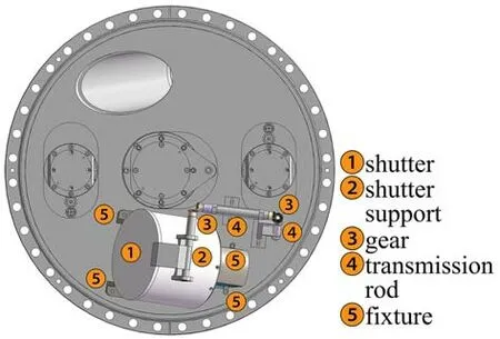
Figure 3.The installation diagram of the LyBES collection system on the HL-2A flange.
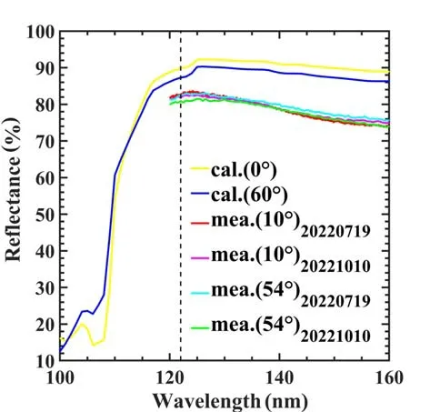
Figure 4.The reflectance of collection mirrors.
The main point for testing the collection optics is to check if the imaging quality could satisfy the demands,with the designed object distance and image distance.The testing of the imaging performance was implemented on the optical platform,as shown in figure 5(a) .A 5μm pinhole diaphragm is coupled with the illuminant to form the pointolite system,which acts as the testing light source for the collection optics.The position of the pointolite could be controlled in three dimensional direction (x,y,z) .The distance between the pointolite and the collection optics is adjusted to be the same distance between the observing point in HL-2A plasma and the collection optics.The camera located on the image plane is used for the detection of the imaging point.The photograph of the shutter support is shown in figure 5(b).
The typical testing result of collection optics detected by the camera is shown in figure 6(a).The pixel with the light falls on is illuminated,and the pixel without the light falls on is displayed as fully black.The 5μm light spot from the observing area is blurred obviously on the image plane,as a result of the optical aberration.As indicated by the partially enlarged figure,i.e.figure 6(b),the geometric (GEO) radius of the point-to-point blur at the image is around 150μm,as the blur profile could be almost completely included by a circle with a radius of 150μm.When the pointolite moved across~9 cm expected range,the focused point changed slightly and the maximum GEO radius of the point-to-point blur is around 150μm.This testing result is in consistent with the previous optical design [17],taking the surface error,the assembling tolerance,and the testing error into account.The imaging quality of the collection optics is well enough for the LyBES system,which has a silicon photodiode detector with an element size of 0.75 mm in the spatial dimension and a 0.2 mm gap between the adjacent two elements [18].
3.2.Monochromator
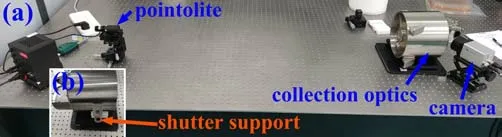
Figure 5.(a) The testing layout of collection optics,(b) photograph of shutter support.
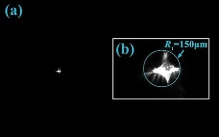
Figure 6.(a) The testing result of collection optics,(b) partial enlarged detail of (a).
As the key component for picking the Doppler-shifted target line out of the strong un-wanted background lines,the monochromator is the most significant and critical part of the LyBES system.In order to obtain sufficiently strong light signal,which is fairly monochromatic for single-wavelength detection,the large-aperture optical elements should be used,and the linear dispersion of the LyBES monochromator needs to be extremely high.The analysis result indicates that the linear dispersion should be better than 0.14 nm mm-1[17].
On a comprehensive consideration of manufacturing difficulty,production cost,and schedule,the monochromator with Czerny-Turner configuration was finally adopted,as shown in figure 7.The main elements of the monochromator include the slit,the collimating mirror,the grating,and the focusing mirror.The input light from the entrance slit is converted to the parallel light after the reflection of the collimating mirror,and the parallel light is dispersed by the reflective plane grating.The grating,which contains a microscopic and periodic groove structure,splits incident light into multiple beam paths through diffraction,causing light of different wavelengths to propagate in different directions.The fluorescence at the wavelength of interest will finally be focused and imaged by the focusing mirror on the detector for photovoltaic conversion.For a better imaging performance,the collimating mirror and the focusing mirror are all off-axis parabolic mirrors.The size of the collimating mirror,the grating,and the focusing mirror are as large as 230 mm × 215 mm,210 mm × 200 mm,and 230 mm ×110 mm,respectively.It could be noticed that one corner of the collimating mirror is partially cut,and this is the integrated optimized result for maximizing the optical throughput and the limited placing space.The available limited space for placing the LyBES monochromator is almost unreservedly taken up.Besides,the 66° off-axis angle of the collimating mirror is also decided for avoiding workspace interference,which is very unfavorable for the monochromator performance.The 30° off-axis angle of the focusing mirror is the optimized result,considering both the available space and the imaging performance.The linear dispersion of the LyBES monochromator is designed to be~0.09 nm mm-1,which means a better dispersion ability and spectroscopic performance compared with the aimed 0.14 nm mm-1linear dispersion.
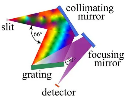
Figure 7.The schematic optical diagram of the LyBES monochromator.
In the cause of avoiding the rapid attenuation of the observing fluorescence when it passes through the air,the vacuum mechanical structure of the LyBES monochromator system is designed and fabricated,as shown in figure 8.Also,limited by the placing space around the HL-2A vacuum port,the mechanical structure is irregular.The material of the monochromator mechanical structure is completely 316L stainless steel.The core part of the mechanical structure is the optical backplane,on which all the optical elements are mounted.The optical backplane is covered with mounting holes and location holes for installation and commissioning.The thickness of the optical backplane is 20 mm,which is thick enough for optical stability and is in accordance with vacuum standards.The optical backplane is vacuum sealed by combining it with the vacuum chamber.At first,the optical backplane and the vacuum chamber were designed to be sealed by metal wire.However,the thickness of the optical backplane cannot be greater than 20 mm,as it is limited by space.Further analysis suggests that these are risks of vacuum leak and deformation of the optical backplane when all-metal sealing is employed.Therefore,vacuum sealing with a fluorine rubber ring is utilized,because the stress applied on the optical backplane could be significantly reduced in comparison with all-metal sealing.
The detection system,which is comprised of the detector,the amplification circuit,the thermoelectric cooler(TEC),the temperature sensor,the electromagnetic shielding structure,the water-cooling flange,the analog-to-digital converter (ADC) and the power supply,is installed on the vacuum chamber through the CF150 flange.The position and the angle of the detector are adjustable,for the coupling with the optical path of the LyBES monochromator.The optical components are fixed and cannot be adjusted once installed.Besides,the LyBES system focuses on the observing of the Doppler-shifted Lyman-alpha line,and cannot be able to look at other emission lines.The position and the angle of the detector have been fixed before system installation.The total weight of the LyBES monochromator is approximately 200 kg,and the size of the LyBES monochromator is approximately 554 mm × 524 mm × 309 mm.
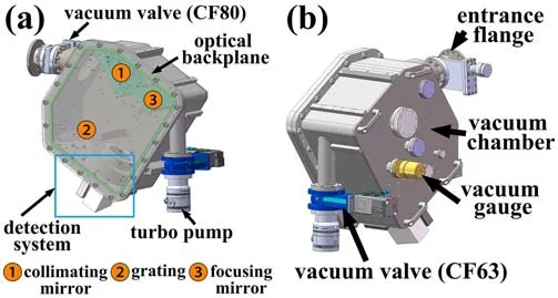
Figure 8.The mechanical structure of the LyBES monochromator system.
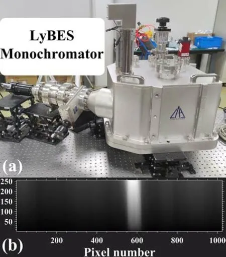
Figure 9.(a) Photograph of the LyBES monochromator,(b) the preliminary testing result.
The monochromator was precisely adjusted and assembled,as shown in figure 9(a).It is to be noted that the monochromator in figure 9(a) is developed based on the requirements of HL-2A,which is consistent with the engineering design in figure 8.Preliminary testing of the monochromator was conducted under the vacuum,as shown in figure 9(b).The testing light source is the deuterium lamp.The Lyman-alpha line of deuterium was detected,which proved the usability and applicability of the monochromator in the vacuum.The background of figure 9(b) is not completely black,due to the continuous output in the spectral bands.However,the effect of neutral beam injection and a resulting Doppler-shift could not be evaluated in this preliminary testing,which is of great significance for the LyBES diagnostic.Therefore,an all-round and precise testing of the monochromator will be carried out on the HL-2A tokamak for a comprehensive performance analysis.
3.3.Detector system
After light diffraction and focusing by the monochromator,the aimed spectrum signal is imaged on the detector plane for photoelectric conversion.In order to improve system signal-to-noise ratio (SNR),the Absolute eXtreme Ultra Violet silicon photodiode array (model AXUV20ELG,Opto.Diode Corporation) is chosen as the detector for LyBES,which has a high internal quantum efficiency [18].The detector is working under the vacuum condition,which is vacuum sealed with the CF150 flange,as shown in figure 10.The CF150 flange is made of 316L stainless steel as well,and is demagnetized with high-temperature treatment.
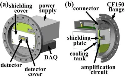
Figure 10.(a) The mechanical structure of the LyBES detector system,(b) the sectional view of the LyBES detector system.
In order to reduce the dark current of the detector,the semiconductor thermoelectric cooling (TEC) apparatus is put below the detector and is pressed by the shielding plate and the detector cover.There is a silicone based thermal gap filler filled between the detector and the TEC with a 7.5 W mK-1thermal conductivity,which is used for better thermal conduction.The amplification circuit,which is used for signal amplifying and filtering,is placed under the detector and TEC.The heat transfer between the TEC,detector,the amplification circuit in vacuum and the air is through the water-cooled CF150 flange,in which the cooling tank is shown in figure 10(b).The nominal cooling capacity of the industrial water chiller is 1.4 kW and features a controllable temperature,which is far exceeding the cooling demands for the temperature stability of the detector system.There are also shielding plate,silicone based thermal gap filler between the TEC,the amplification circuit and the CF150 flange,so as to have a better heat dissipation capability.The temperature of the TEC cooling surface is designed to be adjustable between -18 °C and 25 °C,considering that the minimum operating temperature of the detector is -20 °C under a vacuum environment.The temperature of the detector could have real-time feedback through a temperature sensor affixed to the detector.The dark current of the AXUV detector,which is estimated by the gained voltage signal in a dark environment,was tested at room temperature and under cooling status respectively.The testing results show that the voltage signal is about 500 mV at 35 °C and about 7 mV at-12 °C,which decreases approximately 70 times with a temperature reduction of 47 °C.
For diagnostics of fusion devices,electromagnetic interference is a long-standing problem,and several measures are taken to reduce electromagnetic interference for the LyBES system.The amplification circuit and the detector are completely covered by the shielding plate,the shielding cover and the detector cover,except for the detecting surface of the detector,which is back to the HL-2A.The material of the shielding plate,the shielding cover and the detector cover is all oxygen free copper (OFC),which is specially chosen for its high thermal conductivity,high electromagnetic shielding performance and low outgassing rate.Besides,the monochromator chamber and the CF150 flange could also act as a shell for electromagnetic shielding.In addition,the data acquisition (DAQ) module is customized and is set to be directly linked to the CF150 flange to shorten the distance between the DAQ and the amplification circuit,in order to reduce the crosstalk and other noise.The DAQ is fully covered by an aluminum box.The signal transmission and power supply of the amplification circuit are via the sub-D vacuum connector,which is welded on the CF150 flange with low temperature.Moreover,the linear power supply with the parameter of 12 V and 3 A is designed to be installed on the CF150 flange directly.

Figure 12.The noise testing result of the LyBES detector system.
The photograph of the LyBES detector system is shown in figure 11.The detector has 20 photodiode elements with a linear arrangement.Each element has a 0.75 mm × 4.1 mm active area and a 0.2 mm gap width between adjacent elements.The detector array location is precisely adjusted by using a high-accuracy monochromatic light source.The accurate wavelength position of the un-shifted Lyman-alpha line and the Doppler-shifted Lyman-alpha line on the detecting plane could be determined by adjusting the wavelength of the monochromatic light source.The responsivity of the detector is 0.16 A W-1at 121.98 nm.For the signal amplification,the amplification circuit is designed with high gain.The overall gain of signal amplifiers is 5×10⁷V A-1with a designed bandwidth of 200 kHz.The practical gain and bandwidth of all 20 channels are tested in the laboratory,and the practical gain is almost the same as the designed value(5.00×10⁷-5.03×10⁷V A-1).The amplification circuit bandwidth of the LyBES system is verified to be around 280 kHz(279-281 kHz),which is higher than the designed value.
The noise testing is also carried out for the detector system of the LyBES diagnostic,as illustrated in figure 12.The noise peak-to-peak value is tested to be~16 mV,which is acceptable for the LyBES system.The digitization is performed with the 20-channel customized DAQ.The maximum sampling rate of DAQ is 2 MHz,which is adjustable,and the resolution is 16-bit for each channel.The overall results show that the parameters of the detector system are equal to or higher than the designed values,which are adequate for the needs of the LyBES system.
4.Summary
The engineering design and performance testing for components of the first LyBES diagnostic on the HL-2A tokamak have been presented in this article.Compared with conventional BES,the LyBES system is expected to have a significantly improved spatial resolution of about 3.3 mm and higher signal intensity,while maintaining the same temporal resolution.The collecting,filtering,imaging and detecting of the Doppler-shifted Lyman-alpha line,which is observed by the LyBES system,are of great challenge with the intent of high efficiency and high accuracy.Limited by the available space and lead time for components,some optical properties have to be compromised in design.
The system design and key component selection of the LyBES system are entirely different from that of the conventional BES,including the collection optical system,the filter system and the detecting system.Based on the optical design in our previous work,the engineering design of the collection optical system is further optimized and tested.The testing results show that the reflectance of the collection mirrors is~82% at 122 nm,and the aberration geometrical radius of the collection optics is~150μm in the observing area.The durability testing of the mirror coating is also carried out,and the result indicates that the reflectance changes slightly.The optical and engineering design of the monochromator is modified,which could be more suitable for HL-2A.The detector system,the electromagnetic shielding and cooling of which are already taken into consideration,features a signal gain of 5×10⁷V A-1,a bandwidth of~280 kHz and a maximum sampling rate of 2 MHz.The overall testing and analyzing results indicate that the components are appropriate and could meet the performance requirements of the LyBES system.
Currently,the development of the LyBES diagnostic is almost completed.The performance testing of LyBES components has been conducted,and the testing results show that all LyBES components achieved anticipated requirements in the design stage.All components are ready and the performance of LyBES diagnostic is to be further confirmed in the next HL-2A campaign.
Acknowledgments
This work is supported by Sichuan Science and Technology Program (No.2022JDJQ0038),the National Key R&D Program of China (Nos. 2022YFE03100002 and 2018YFE0303102),and National Natural Science Foundation of China (Nos.12205087 and 12075241).
猜你喜欢
杂志排行

Plasma Science and Technology的其它文章
- An improved TDE technique for derivation of 2D turbulence structures based on GPI data in toroidal plasma
- Inward particle transport driven by biased endplate in a cylindrical magnetized plasma
- Forward modelling of the Cotton-Mouton effect polarimetry on EAST tokamak
- Development of a toroidal soft x-ray imaging system and application for investigating three-dimensional plasma on J-TEXT
- Electron density measurement by the three boundary channels of HCOOH laser interferometer on the HL-3 tokamak
- Reconstruction of poloidal magnetic field profiles in field-reversed configurations with machine learning in laser-driven ion-beam trace probe