Optical design of a novel near-infrared phase contrast imaging (NI-PCI) diagnostic on the HL-2A tokamak
2024-04-06HaoXU徐皓ShaoboGONG龚少博YiYU余羿MinXU许敏TaoLAN兰涛ZhibinWANG王志斌ZhongbingSHI石中兵LinNIE聂林GuangyiZHAO赵光义HaoLIU刘灏YixuanZHOU周艺轩ZihaoYUAN袁子豪ChenyuXIAO肖晨雨andJianCHEN陈坚
Hao XU (徐皓) ,Shaobo GONG (龚少博) ,Yi YU (余羿),* ,Min XU (许敏) ,Tao LAN (兰涛) ,Zhibin WANG (王志斌) ,Zhongbing SHI (石中兵),Lin NIE (聂林),Guangyi ZHAO (赵光义),Hao LIU (刘灏),Yixuan ZHOU (周艺轩),Zihao YUAN (袁子豪),Chenyu XIAO (肖晨雨) and Jian CHEN (陈坚)
1 Sino-French Institute of Nuclear Engineering and Technology,Sun Yat-sen University,Zhuhai 519082,People’s Republic of China
2 Southwestern Institute of Physics,Chengdu 610041,People’s Republic of China
3 School of Nuclear Science and Technology,University of Science and Technology of China,Hefei 230026,People’s Republic of China
Abstract The optical design of near-infrared phase contrast imaging (NI-PCI) diagnosis on HL-2A is introduced in this paper.This scheme benefits from the great progress of near-infrared laser technology and is a broadening of traditional phase contrast technology.This diagnostic can work as a keen tool to measure plasma wavenumber spectra by inferring string-integrated plasma density fluctuations.Design of both the front optical path which is the path before the laser transmitting into the tokamak plasma and the rear optics which is the path after the laser passing through the plasma is detailed.The 1550 nm laser is chosen as the probe beam and highprecision optical components are designed to fit the laser beam,in which a phase plate with a 194-nm-deep silver groove is the key.Compared with the conventional 10.6 µm laser-based PCI system on HL-2A,NI-PCI significantly overcomes the unwanted phase scintillation effect and promotes the measurement capability of high-wavenumber turbulence with an increased maximal measurable wavenumber from 15 cm-1 to 32.6 cm-1.
Keywords: phase contrast imaging,near infrared laser,plasma laser diagnostic
1.Introduction
In tokamak plasmas,experimental data show that radial transport exceeds the predictions of the neoclassical theory by more than several orders of magnitude,and this anomalous transport phenomenon is widely believed to be caused by turbulence driven by plasma density and temperature gradients.Typical turbulences due to drift wave instabilities are ion temperature gradient mode (ITG),trapped electron mode (TEM),and electron temperature gradient mode(ETG) [1-4].A key difference among these turbulence types is that they have different wavenumber ranges.In the wavenumber domain,turbulent energy is transferred from lower to higher wavenumbers through cascades,which leads to turbulence that can exhibit complex broad-spectrum characteristics.To gain insight into the fundamental physical properties of turbulent energy cascades,or the interaction mechanisms between different scales of turbulence,a broad wavenumber range density fluctuation diagnosis of multiscale turbulence is required.
In tokamaks,most diagnostic methods can only detect turbulent signals at low wavenumber,such as Beam Emission Spectroscopy (BES) [5],Gas Puffing Imaging (GPI)[6],Microwave Reflectometry [7].Far-Infrared Scattering [8]is well developed to diagnose high wavenumber turbulent signal,but it can only measure turbulence with specific wavenumber,limited by scattering angle.Phase Contrast Imaging (PCI) [9] allows simultaneous diagnosis of plasma density fluctuations over a wide wave number range and is a powerful tool for studying multi-scale turbulence in tokamak core or edge regions.
A conventional PCI diagnostic based on a 10.6 µ m CO2laser beam has recently been applied in its entirety on the HL-2A tokamak and it shows its nice promising wavenumber diagnosing upper-limit of 15 cm-1[10 ].For a higher wavenumber,the phase scintillation effect will cause significant response degradation which has an oscillating waveform and is proportional towherekpstands for plasma wavenumber,k0stands for the wavenumber of laser beam andLis the plasma integration path [11].The discussion of this scintillation effect brightens an effective way to broaden the wavenumber diagnosing range of PCI,i.e.,applying a laser with a shorter wavelength as the laser probe.In this paper,we present the design of a novel NI-PCI system based on a 1550 nm continuous fiber laser,which is under development on the HL-2A tokamak.Unfortunately,substituting the 10.6 µ m CO2laser of traditional PCI with a 1550 nm laser of NI-PCI brings big technical challenges although great progress in the 1550 nm laser and its related instruments has been achieved in the last decade along with its wide usage in the communication field and industry.These challenges are mainly reflected in the manufacturing difficulty of the phase plate and the weak response of the system,so a good optical design is required to cope with it first.
The rest of this article is organized as follows: section 2 introduces the phase scintillation effect and PCI diagnostics on the HL-2A;section 3 presents the design scheme of the beam expanding optics;section 4 describes the design of the imaging optics,especially the phase plate;section 5 is a brief discussion and conclusion.
2.PCI diagnosis and phase scintillation effect
PCI diagnosis is a kind of self-interference spectral diagnosis,without the need for an external reference beam,and indirectly realizes the string integral measurement of density by measuring the plasma refractive index.In the PCI diagnosis,both scattered and unscattered lights originate from the same outgoing laser and always pass through the same spatial region,so their relative phase is not affected by plasma or mechanical vibrations of the mirror.This selfinterference property of the PCI method makes it an important diagnostic tool in the measurement of fusion plasma density fluctuations.
The phase scintillation effect is the main factor limiting the upper limit of wave number measurement of the PCI system,which is directly related to the detection beam wavelength.After considering the phase scintillation effect and the transmission of unscattered light by the phase plate substrate,the total light intensity of the PCI system collected on the imaging surface is [12]:
whereI0and λ0represent the light intensity and wavelength of the incident laser,Ris the reflectivity of the phase plate substrate andkpand λpmean the wavenumber and w∫avelength of the plasma density fluctuation,Δ=-λ0redenotes the phase shift due to plasma density fluctuations,the classical electron radiusre=2.8× 10⁻¹⁵m,andrepresents the amplitude of the density fluctuations.
The PCI technique converts the phase change of the probe beam into the light intensity change in the image plane and then applies the Fourier transform to solve the frequencywave number spectrum of the density fluctuation.As seen from equation (1),the phase scintillation factor isthen when the plasma integration pathLis determined,the intensity signal of PCI will rapidly decrease for density fluctuations with high wavenumber;and when the wavenumber exceeds a certain value,the phase change will be equivalent to the period,resulting in a complete failure of the response.Under ideal conditions,the plasma is an infinitely thin scattering layer withL=0 and the phase scintillation effect is neglected;while in reality,the plasma will be distributed on the integration path and the light intensity at different locations is different when the object plane is fixed.For an integral pathLof determined length,we define the distance as the depth of field when the signal strength drops to the originalthen the wavelength satisfies≥4λ0L,i.e.,the maximum wavenumber is determined.
HL-2A is the first tokamak device with the divertor configuration in China,and PCI diagnosis uses two vertically opposite windows.As shown in figure 1,the inner diameter of the window is 35 mm,located at the small plasma radius of 0.625
3.Beam expanding optics
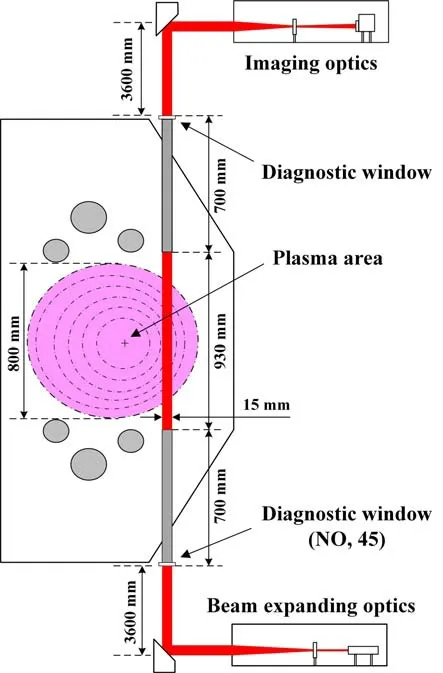
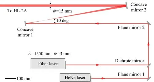
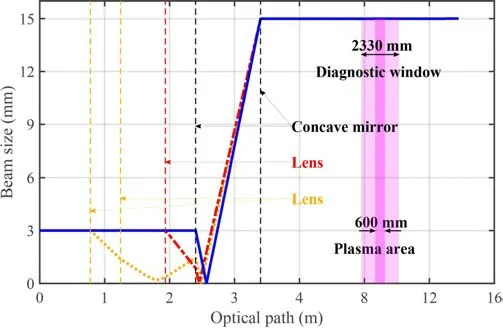
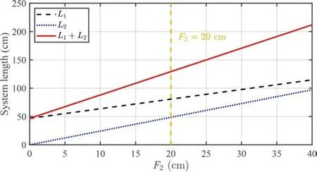
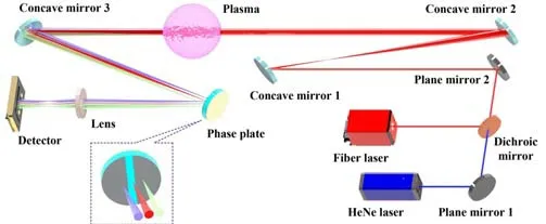
Figure 1.NI-PCI laser path topology diagram in HL-2A.The purple is the plasma region,and the laser passes through the region at position 0.625 The 1550 nm wavelength is generally considered to be a better wavelength range for optical interference,which has a small refractive index and absorption in many optical materials,therefore it is widely used in Optical Fiber Communication,Optical Sensing and Interferometric Imaging.For the PCI system,the wavelength accuracy and power stability of the laser are particularly important,so the 1550 nm continuous fiber laser (AT-1550-CW-10-T) with a spectral linewidth ≤0.1 nm,output power 10 W (continuously adjustable),and power stability (8 h) ≤±1.2% was finally selected. In the analysis of section 5,it can be obtained that a larger beam diameter implies better wavenumber resolution,however,the beam diameter cannot be increased indefinitely due to the diagnostic window size.On the HL-2A tokamak,the inner diameter of the vertical window for PCI diagnostics is 35 mm.When the beam diameter is comparable to the window diameter,diffraction effects must be considered.At this time,non-negligible diffraction will occur when the edge part of the laser passes through the diagnostic window,and the plasma density fluctuation information it contains is no longer credible.When the window diameter is determined,the range affected by diffraction on the beam profile can be evaluated by solving the ratio of the diffracted field to the undiffracted field under different beam diameters [15].In general,the shorter the laser wavelength,the weaker the diffraction effect,which implies that the NIPCI system with 1550 nm is much less affected by diffraction than conventional PCI.Additionally,another important effect comes from the engineering errors of the device.For a large tokamak,offsets on the order of mm in the size of the windows and in the alignment of the upper and lower windows are common.Considering the above two points,the final expansion size of the NI-PCI system is designed to expand the beam from 3 mm diameter to 15 mm diameter. The laser beam expanding system can be divided into the transmissive type and reflective type according to the propagation form of the laser.Compared to the reflective type,the transmissive beam expansion system is more compact and has less aberration.However,due to the heat-absorbing properties of optical materials,the system aberration tends to change with temperature,which can affect the normal use of the system and may even cause damage to the lens when the temperature continues to rise.The commonly used reflective beam expansion systems can be broadly classified into two types: Cassegrain and Gregorian systems,which can be further divided into axisymmetric and off-axis configurations.In the axisymmetric configuration,the light from the center of the laser returns in the original direction and the laser loses this part of the energy;while in the off-axis configuration,the laser energy is completely retained.After comprehensive consideration,the off-axis Gregorian system was selected as the initial beam expansion solution for NIPCI. In an off-axis reflective beam expansion system,the ideal solution is to choose two confocal parabolic mirrors,where a beam of light emitted from the parabolic focus and reflected by the mirrors will be perfectly parallel to the optical axis.However,considering the difficulty of machining and commissioning of off-axis parabolic mirrors,spherical mirrors were finally chosen instead in this system.Inevitably,spherical mirrors introduce additional spherical aberration compared to parabolic mirrors,but this aberration is acceptable for PCI systems.The overall design of the final NI-PCI system beam expansion scheme is given in figure 2,in which HeNe laser is used to debug the optical path.According to simple geometric optical calculations,when the beam expansion ratio is 5 times,the ratio of the focal lengths of the two concave mirrors placed in confocal should also be 5,meanwhile,the two plane mirrors are used to increase the spatial compactness of the front optical path. Figure 2.The overall design of the front expansion optics.The offaxis reflective beam expansion scheme is adopted,and the parabolic mirrors are replaced by concave mirrors. In general,the light wave emitted by a laser will not be an ideal parallel beam,but a more natural Gaussian beam,which is the solution of the wave equation in a cylindrical coordinate system.The propagation of a Gaussian beam in an optical system is more complicated than that of a parallel beam.On one hand,rigorous physical-optical calculations can be made;on the other hand,under near-axis conditions,the near-axis Gaussian equation can be used for calculations.In this paper,the full optical path is optimized based on the Zemax OpticStudio®optical design tool.Zemax can handle the propagation of Gaussian beams in optical systems well,and can automatically find the approximate optimal optical path settings to meet the requirements by setting a reasonable number of operators and evaluation functions. The key to optical path optimization is to obtain a Gaussian beam with a specified diameter (15 mm) and good collimation.This means that within the scale range of HL-2A plasma (m order),the diameter of the Gaussian beam should have a small variation to ensure the rationality of PCI diagnosis.In this optical path,the main optimization parameters are the focal length,tilt angle,and relative distance of the two concave mirrors.After the Zemax simulation,the effect of the tilt angle of the concave mirror proved to be weak,so we chose an angle suitable for the optical path commissioning,i.e.,an angle of 10 degrees with the laser incidence direction.Based on this,the first step of the simulation is to determine the relative distances of the two concave mirrors.When the relative distance is set to 1000 mm,the focal lengths of the two concave mirrors aref1=168 mm andf2=832mm after Zemax optimization.At this time,the sum of the focal lengths is almost equal to the relative distance,which indicates that the two concave mirrors are placed in a confocal state and the beam expansion ratio is the ratio of focal lengthsf2/f1=4.96 ≈5.This almost overlaps with the inference of geometrical optics,and the subtle differences may come from the Gaussian beam.In fact,for a fixed beam expansion ratio,the relative distance of a concave mirror is essentially determined by its focal length,and thus for the convenience of lens processing,the focal length is generally determined first. For a long optical path,when considering the propagation of a Gaussian beam,focusing lenses should generally be properly added to the optical path to collimate the Gaussian beam.In practical engineering applications,this scheme is regularly used.However,the addition of such focusing lenses is usually empirical and rarely analyzed quantitatively.In this section,the beam expansion and collimation effects of three different optical path design schemes are compared and analyzed,corresponding to the three design schemes of no focusing lens,one focusing lens and two focusing lenses respectively.It should be emphasized that under each scheme,the parameters of the concave mirror were optimized using the Zemax tool to obtain the best optical path.The results are shown in figure 3.The blue line indicates that no focusing lens is arranged,the red line indicates that only one focusing lens is arranged,and the yellow line indicates that two focusing lenses are arranged.The positions of the focusing lenses are marked with vertical dotted lines of corresponding colors,and the focal lengths of the lenses are calculated by Zemax.To highlight the effect of the focusing lens on the beam size,the part of the optical path from 0 to 4 m is uniformly enlarged.As can be seen in figure 3,no matter whether the focusing lens is added or not,the ideal beam expansion and collimation effect can be obtained by optimizing the parameters of the concave mirror,that is,the beam size in the plasma region is guaranteed to be 15 mm and remains basically unchanged.In this case,the divergence half-angle of the outgoing beam after the front beam expansion system is less than 3.3×10⁻⁵rad,that is,the Rayleigh length is greater than 4.5×10²m,which fully meets the design requirements.This result will be briefly discussed below. Every time a Gaussian beam passes through a lens or a concave mirror,its radius and position of the beam waist will change [16]: Figure 3.Effect of focusing lens on beam size.The beam expansion schemes corresponding to three different numbers of focusing lenses are compared: no lens (blue solid line);one lens (red dotted line);two lenses (yellow dotted line). wherefis the focal length,w0is the initial beam waist radius,z0is the Rayleigh length,ldenotes the initial beam waist position,andandl' denote the transformed radius and position of the beam waist,where the positive and negative signs of the first term correspond to the lens and the concave mirror,respectively.In the collimation of Gaussian beams,the so-called telescopic collimation scheme is generally used,that is,firstly,a short-focus lens is used to focus the Gaussian beam to obtain a very small beam waist radius;then a long-focus lens is used to improve the directionality of the beam,and finally achieve collimation.Through equation (2),considering the continuous transformation of Gaussian beams by two lenses,the collimation magnification of this collimation system can be obtained as: The main purpose of imaging optics is twofold: focusing the Gaussian beam to generate the position of the phase plate that can distinguish the scattered beam from the unscattered beam;amplifying the density fluctuations signal to make the image match the size of the detector at the image plane.To achieve these two points,at least two lenses or reflectors can meet the requirements.On the HL-2A,the optical platform can be placed on the top of the device after a special design.Considering the influence of electromagnetic interference and device vibration,the optical path should be designed to be compact and simple.Fortunately,with the development of laser technology,the power stability of 1550 nm continuous fiber laser with high beam quality can reach more than 0.5 %;meanwhile,the InGaAs semiconductor infrared detector with high sensitivity and fast response in the 1-3 µm band has also been developed rapidly.In addition,advances in ultra-precision processing and detection technology have also made it possible to manufacture the phase plate with a reflective coating with nanoscale precision. The size of the infrared detector unit is generally on the order of mm.When measuring plasma fluctuations on the order of cm,it is necessary to design the imaging optical path to obtain a suitable magnification.The design of the magnificationMneeds to take into account the area of the detector,the distance between the centers of the detection units isd0=0.25 mm,and the corresponding projection distance in the plasma is Δx=d0/M.The number of units in the one-dimensional detector array isN,if the enlarged laser cross-section covers the entire detector,D=NΔx=d0/Mis satisfied.If the number of detector units isN=32,the design magnificationM=0.53 can be calculated. The overall design of the imaging optical path is shown in figure 4.Regardless of the Gaussian beam,it can be calculated from geometric optics: Considering imaging twice,the vertical axis magnificationM=can be substituted into equation (4): Generally speaking,L0andF1in the system are fixed and cannot be changed.In this system,L0=4600 mm andF1=1250mm.If the magnification is determined,according to equation (5),the system parameters have the only degree of freedom.In addition,in the system construction,it is necessary to keep the position of the detector and the phase plate unchanged,that is,L1+L2is determined.At this time,if the lens focal lengthF2is changed,thenL1andL2satisfy: It can be seen from figure 5 that as the lens focal lengthF2increases,the length of the system increases rapidly.Due to the space limitation of the test bench,we do not want the distance between the phase plate and the detectorL1+L2to be too large.After comparison,the focal length of the lens is finally selected asF2=20 cm.At this time,L1=80.6 cm,L2=48.6cm,and the distance between the phase plate and the detector isL1+L2=129.2 cm. Figure 4.The overall design of imaging optical path. Figure 5.Variation of L1,L2 and L1+L2 with lens focal length F2. Finally,the above design parameters are substituted into the Zemax program for further optimization,considering the propagation of the paraxial Gaussian beam.Combined with the beam expansion optical part in section 3,the overall optical path design of the NI-PCI system has been completed,please refer to figure 6 for the complete optical path. The phase plate is the most important optical component of phase contrast imaging technology,and the parameter design of the phase plate significantly determines the quality of phase contrast imaging.According to the propagation mode of light through the phase plate,it can be divided into two design schemes: reflective and transmissive.This system adopts the reflective design shown in figure 7,with fused silica as the substrate,the upper surface is covered with a silver film of λ0/8,a groove of a certain width is opened in the middle of the silver film,and the lower surface is coated with an anti-reflective coating.At a wavelength of 1550 nm,the substrate material needs to have extremely high transmittance.According to equation (1),the higher the substrate transmittance,the higher the light intensity contrast between the scattered component and the unscattered component,thereby improving the signal-to-noise ratio.Fused silica has a transmittance greater than 95% at 1550 nm and is the best choice for the substrate material.In addition,the reflectivity of silver at 1550 nm is greater than 99%,which can preserve the intensity of the scattering component to the greatest extent.The lower surface is further coated with an antireflection coating,and a power meter is used to detect the transmitted light intensity to ensure that the unscattered component is in the center of the groove and minimize interference. Figure 6.Schematic diagram of the complete optical path of the NIPCI system. Figure 7.Side view (a) and top view (b) of the phase plate.The phase plate is based on fused silica,the upper surface is plated with λ0/8silver coating,a groove is opened in the middle of the silver coating,and the lower surface is coated with an anti-reflection coating. A Gaussian beam with a diameter ofDis reflected by a concave mirror to form a spot with a diameter ofd=on the focal plane.According to the Bragg scattering condition,the center distances(see figure 7(b)) between the scattered beam spot and the unscattered beam spot at the phase plate can be obtained from the scattering angle as: For the PCI system to obtain a good response,the unscattered beam spot should be located in the groove of the phase plate as much as possible,and the scattered beam spot should be located outside the groove as much as possible,which means that the central groove widthwneeds to satisfy: Obviously,too large or too small groove widthwis inappropriate,and the selection of a suitable groove widthwoften depends on actual needs.Generally,the groove width is designed asw=If the system requires better response and linearity,a largerwcan be used,and if the density fluctuations at long wavelengths are of interest,wshould be decreased.For the NI-PCI system of HL-2A,D=15 mm,λ0=1550 nm,F=1250 mm,calculated to getw=258.3 µm. Choosing a material with low reflectivity for the phase plate substrate can reduce the light intensity of the unscattered part,increase the contrast during imaging,and improve the signal-to-noise ratio.Obtained from equation (1),the imaging contrast is δI/I=cos(kpx),where the phase shift amplitude Δ=-λ0rethe laser wavelength λ0=1550 nm,and the classical electron radiusre=2.8×10⁻¹⁵m.For the HL-2A device,the plasma integration lengthL=600 mm,the typical value of the plasma density isne=1019m-3,then the peak value of the density fluctuation can be taken as=1017-1018m-3.Substituting into the calculation,the phase shift amplitude Δ=2.6× 10⁻⁴-2.6 ×10⁻³,and the imaging contrast amplitude|δI/I|=0.3%-2.9%. Through imaging optics,the beam is designed to just completely cover the detector array.Since this system uses a one-dimensional 32-channel InGaAs detector array (Hamamatsu,G12430-032D),only a small part of the center of the beam can irradiate the detector.The total laser powerPlaser=5 W,approximately,the effective power irradiated to a single detector unit isPeff=0.02 W.The phase plate substrate is made of fused silica,and its typical reflectanceR=3% for the laser wavelength λ0=1550 nm.The laser light intensity is proportional to its power.It can be seen from equation (1) that the PCI signal is finally composed of two parts,the baseline signal amplitudePDC=R·Peff=655 µW,and the fluctuation signal amplitudePAC=Peff=1.9-18.8µW. The detector converts the optical signal into an electrical signal.For the InGaAs detector,at the wavelength λ0=1550 nm,its typical responsivity is 0.95 A W-1,then the corresponding DC baseline signalIDC=622µA,and the AC signalIAC=1.8-17.9µA.The typical value of the dark current of the detector G12430-032D is 250 pA,and this signal can be well responded by the detector.Then,through the preamplifier circuit,the baseline signal is filtered out,and the AC signal is collected and transmitted to the computer.At present,the design of the preamplifier circuit has been completed and production has begun,with a transimpedance gain ofZT=60 kΩ and a bandwidth of 2 MHz. NI-PCI diagnostic is to infer string-integrated plasma density fluctuations by measuring the phase shift of the 1550 nm laser beam in tokamak plasma.Compared with other plasma density diagnostics in tokamaks,the main benefit of a PCI system is its ability of calculating wide-range wavenumber spectra which is very important to study multi-scale turbulence.For the traditional PCI system on HL-2A,the measured wavenumber ranges from 2 cm-1to 15 cm-1.This wavenumber range covers the wavenumber from ITG(kρi<1,where ρistands for ion gyration radius) to TEM(kρi≥1) and it almost reaches lower wavenumber limit of ETG (kρi>20 andkρe<1,where ρestands for electron gyration radius).This novel NI-PCI diagnostic,whose wavenumber measurement range is significantly improved comparing with traditional PCI,provides a potential way to investigate ETG physics. It must be mentioned that,limited by the size of the HL-2A window,the diameter of the beam entering the plasma from the beam expanding optics is also restricted.On one hand,this limitation increases the lower limit of wavenumber measurement,and on the other hand,it also weakens the wavenumber resolution capability of the system.This NIPCI diagnostic will be moved to HL-3 tokamak soon and two vertical vacuum ports with a diameter ofD=80 mm are chosen for NI-PCI,which means wavenumber resolution Δkp=2π/D=0.8cm-1.Meanwhile,the increase in window size will significantly mitigate the influence of the diffraction effect on wave number responsiveness. In this paper,a novel NI-PCI system based on a 1550 nm wavelength laser is proposed,and the design of the optical path and the parameter selection of the key optical components are discussed in detail.The complete schematic of the optical path is given in figure 6.In the future,this system will soon be applied to HL-2A and HL-3 devices,respectively,and become a keen tool for studying multi-scale turbulence in core or edge tokamak plasma. Acknowledgments The authors thank the HL-2A team in SWIP for the help of diagnostic design.This work is supported by the National Key Research and Development Program of China (Nos.2019YFE03090100 and 2022YFE03100002) and National Natural Science Foundation of China (No.12075241).3.1.Overall design of the beam expansion scheme
3.2.Position and parameter optimization of concave mirrors
3.3.Discussion of focusing lenses
4.Imaging optics
4.1.Imaging design

4.2.Phase plate

4.3.Estimation of signal amplitude
5.Discussion and summary
猜你喜欢
杂志排行

Plasma Science and Technology的其它文章
- Forward modelling of the Cotton-Mouton effect polarimetry on EAST tokamak
- First results of CO2 dispersion interferometer on EAST tokamak
- Reconstruction of poloidal magnetic field profiles in field-reversed configurations with machine learning in laser-driven ion-beam trace probe
- Electron density measurement by the three boundary channels of HCOOH laser interferometer on the HL-3 tokamak
- Development of a toroidal soft x-ray imaging system and application for investigating three-dimensional plasma on J-TEXT
- Inward particle transport driven by biased endplate in a cylindrical magnetized plasma