Inward particle transport driven by biased endplate in a cylindrical magnetized plasma
2024-04-06YueGE盖跃TianchaoXU徐田超ChijieXIAO肖池阶ZhibinGUO郭志彬XiaogangWANG王晓钢RenchuanHE何任川XiaoyiYANG杨肖易ZuyuZHANG张祖煜andRuixinYUAN袁瑞鑫
Yue GE (盖跃) ,Tianchao XU (徐田超),* ,Chijie XIAO (肖池阶),* ,Zhibin GUO (郭志彬) ,Xiaogang WANG (王晓钢) ,Renchuan HE (何任川) ,Xiaoyi YANG (杨肖易),,Zuyu ZHANG (张祖煜) and Ruixin YUAN (袁瑞鑫)
1 State Key Laboratory of Nuclear Physics and Technology,School of Physics,Peking University,Beijing 100871,People’s Republic of China
2 Department of Physics,Harbin Institute of Technology,Harbin 150001,People’s Republic of China
Abstract The inward particle transport is associated with the formation of peaked density profiles,which contributes to improve the fusion rate and the realization of steady-state discharge.The active control of inward particle transport is considered as one of the most critical issues of magnetic confinement fusion.Recently,it is realized preliminarily by adding a biased endplate in the Peking University Plasma Test (PPT) device.The results reveal that the inward particle flux increases with the bias voltage of the endplate.It is also found that the profile of radial electric field (Er) shear is flattened by the increased bias voltage.Radial velocity fluctuations affect the inward particle more than density fluctuations,and the frequency of the dominant mode driving inward particle flux increases with the biased voltage applied to the endplate.The experimental results in the PPT device provide a method to actively control the inward particle flux using a biased endplate and enrich the understanding of the relationship between Er×B shear and turbulence transport.
Keywords: inward particle transport,biased endplate,turbulent transport.
1.Introduction
Particle transport is a critical issue in the pursuit of magnetic confinement fusion [1].For fusion reactors,injecting fuel from the edge is a conventional approach.Since fusion reactions primarily occur in the core,maintaining steady-state discharge requires efficient inward particle transport to the core.Therefore,the active control of particle transport is especial critical for the realization of controlled nuclear fusion.There are many experimental observations and studies of inward particle flux in various devices,such as stellarators [2-4],tokamaks [5-8] and linear devices [9,10].For example,theEr×Bshear flow induced by the radial electric fieldErcan enhance the thermal confinement of plasma,thereby inducing the H-mode [8].It reveals that shear flow influences the production of inward particle flux [3,9,10].Experimental results also indicate that plasma rotation is closely linked to the inward transport of particles [11-14].Many experimental measurements reported that biased electrode-driven shear flow suppresses the edge turbulence and transport on J-TEXT,TCABR and other devices [15-17].The direct cause of inward particle transport is the crossphase between density fluctuationsand radial velocity fluctuations[10].However,the mechanism of inward particle transport is still not studied thoroughly in the experiment
Compared to large toroidal fusion devices,linear devices are simpler in terms of parameter control and have lower plasma density and temperature,which makes it easier to be diagnosed.Moreover,radial electric fields can be more easily introduced into linear devices using biased endplate without breaking polar symmetry [18,19 ].In order to explore the formation of inward particles flux,we set up a biased endplate in the PPT device to control radial electric field.It is found that the inward particle flux increases with the bias voltage and the profile of radial electric field (Er)shear is flattened by the increased bias voltage at the location where the inward particle flux increases.Compared with the density fluctuation,radial velocity fluctuationshas a greater influence on the inward particle.It is also found that the frequency of the dominant mode driving inward particle flux increases with the voltage of biased electrode.The experimental results in PPT device provide a feasible way to regulate the inward particle flux by using a biased endplate and improve the understanding of inward particle flux formation.
This paper reports the active control of inward particle flux in the PPT device.In section 2,the experiment setup and the probe diagnosis are presented.Some preliminary results of the active control of inward particle flux are shown in section 3.In section 4,The low frequency modes driving inward particle flux is discussed.Finally,the conclusions and discussion of this study are given in section 5.
2.Experimental setup
The experiment is performed in the Peking University Plasma Test (PPT) device,which is a linear device for the study of fundamental plasma problems as shown in figure 1.The device has a cylindrical vacuum chamber with about 1 m in length and 0.25 m in radius.A set of Helmholtz coils generates a uniform magnetic field of up to 2000 G in the vacuum cavity.The plasma is generated using a 13.56 MHz helicon plasma source.The power of the helicon source is set at 1500 W and it produces plasma with argon gas.Throughout the discharge of this experiment,a constant neutral pressure of 0.3 Pa was maintained and the density is up to 1×10-13cm-3.The typical ionization fraction of PPT plasma is about 5%-10%.The typical electron temperature is 3 eV,and the typical ion and neutral temperatures are 0.5 eV.With the density profile and ionization fraction,taking the typical ion-neutral collision frequency νin=6×10³s-1,and the typical electron-neutral collision frequency νen=4×10⁶s-1.These parameters are similar to other helicon plasma devices in similar plasma conditions [20].The ion cyclotron frequencyfci=7.7×10⁴Hz,and the electron cyclotron frequencyfce=5.6×10⁹Hz.The electron Hall parameter calculated by βe=ωce/νen=8.8×103,and the ion Hall parameter calculated by βi=ωci/νin=80.Because of βe≫1 and βi≫1,the average motion of the ions (electrons) is dominated byEr×Bdrift rather than by collisions.More details of this device can be found in the previous work [21].

Figure 1.The diagram of PPT device and the configuration of the endplate.
A variety of plasma parameters can be diagnosed using probe diagnostic and high-speed cameras.In this experiment,a 5-tip probe array is used.The probe scanning velocity is 10 mm s-1,and sampling frequency is 600 kHz.The probe array consists of four probes measuring floating potential(Uf) and one probe measuring ion saturation current (Isat)arrange in a cross shape.Detailed information regarding the layout of the 5-tip probe array is referred in the previous work.From the relationEr=-∇φp≅-∇φ-3k∇Te/e,where φpis plasma potential,φ is floating potential,andTeis electron temperature.Under our experimental conditions,∇φ is of order 1000 V m-1,the temperature gradient effect of electrons has a small effect on the plasma potential,which is typically less than 10 eV m-1.Under the assumption of negligible electron temperature fluctuation as described in reference [22],the 5-tip probe array can measure floating potential (Uf) and plasma density (ni),which mean that we can calculate the fluctuation of floating potential and plasma density.The adjacent tips in both theθdirection andzdirection are spaced 4 mm apart.The 5-tip probe array is structured with three stages in the radial direction,with a height difference of 1 mm between each pair of stages.TheEr×Bdrift speed can be estimated by analyzing the floating potential gradients between two adjacentUftips,i.e.,Vr=-∇θUf/B.Various plasma parameters can be calculated,such as fluctuation-induced particle flux (Γ).Fluctuation-induced radial particle flux (Γr) is calculated aswhere 〈·〉 means ensemble average.The sample size is 1×10⁴and the time duration of samples is 1.7×10⁻²s.
The bias endplate consists of three concentric rings of mutually insulated conductors.Alumina ceramic tubes are used for supporting surface insulation,and boron nitride ceramic rods are used for fixation between concentric rings.Each segmented electrode can be biased with independent voltage settings.PTFE (Polytetrafluoroethylene) is used to insulate the end of the vacuum chamber to ensure more effective regulation of the plasma potential by the bias electrode.
The three concentric rings (each 5 mm width,r=42.3,87.0,133.1 mm,z=530.5 mm,as shown in figure 1) insulated from each other are biased to influence the profile of floating potential at the probe position(z=0 mm).The positions of the three rings correspond to the inner,barrier and outer of the plasma at the probe position on the same magnetic line.The three concentric rings are made of stainless steel.The adjustable DC constant-voltage power supply is used to provide the bias voltage between endplate and vacuum vessel.It has a maximum capability of±300 V for the bias voltage and ±20 A for the bias current.In the experiments of this work,the bias voltages and bias currents are only applied to the outer ring,whose radius is 133.1 mm .It is found theUfprofile is more changeable when the outer ring is biased,and the bias voltage cannot be applied to more than one ring simultaneously for spark discharge between two biased rings.The maximum of bias voltage applied is 90 V and the corresponding bias currents is below 0.8 A in this experiment.
3.The active control of inward particle flux
The active control of inward particle flux is realized by changing the profile of floating potential.By controlling the bias voltages applied to the segmented endplate,different radial profiles of the plasma potential can be obtained.The voltage on the outer ring is adjusted from 0 to 90 V in the case of insulated edge conditions,changing the current from 0 to 0.8 A.The position of the bias ring (the shaded area as shown in the figure 2) along the magnetic line corresponds to the edge of plasma atz=0 mm.
It can be observed in the figure 2(b) that the profile of floating potential can be influenced by adding bias voltages on the electrode.With the increase of bias voltages,the particle flux appears and increases gradually.As shown in the figure 2,the increase in bias voltage causes a change in the potential profile,which in turn causes an inward particle flux,and the particle flux increases with the current of bias electrode.The increase of the electric field in the edge(r=40-48 mm) elevates the inward particle flux in the plasma core (r=25-34 mm).It provides a possible method of influencing inward particle transport by applying an electric field.
As shown in figure 2,although the density gradient is always positive,the accompanying inward particle flux (Γn)is up-gradient if -∇rEr>0.The inward particle flux could be driven byErshear.Figure 2 illustrates theErshear flattening accompanied by an inward particle flux as the bias pressure increases.As the bias increases,both internal(r=27-32 mm) and external (r=37-50 mm)Ershear decreases,suggesting that the externally applied bias could affect the plasma particle transport in the core.

Figure 2.Equilibrium profiles of (a) electron density ne,(b) floating potential ϕf,(c) radial electric field Er,(d) negative gradient of Er,(e) fluctuation-induced particle flux Γr of various bias voltages.The positive direction of Er and Γr is point to outward.The shaded area shows the area where bias voltages are added.
Figure 3 shows that the contributions of velocity fluctuations and density fluctuation amplitudes to transport have different trends of change in the outward and inward transport components.Atr=30 mm,where the inward particle flux peaks are likewise where the velocity fluctuationspeaks,and the size of the inward flux is positively correlated with the size of the velocity fluctuations.In contrast,the peak point of the outward flux is close to the valley of the velocity fluctuationsatr=35 mm.When bias voltage is applied,there are two peaks of velocity fluctuations as shown in figure 3(b).One corresponds to the peak of the inward flux and their amplitudes are positively correlated.The other peak is on the outside of the outward flux area and their amplitudes are negatively correlated.As for the density fluctuations,there is only one single peak,which is positioned close to the peak of the outward flux and their amplitudes are positively correlated.It suggests that velocity fluctuations have a greater contribution to the inward particle transport.

Figure 3.Radial profiles of (a) root mean squares of density fluctuations (b) root mean squares of velocity fluctuations and (c)particle flux Γn.
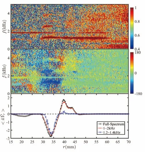
Figure 4.(a) Distribution of crosspower between n and ,(b)distribution of crossphase between and ,(c) radial profiles of particle flux at full-spectrum,f=1-2 kHz,and f=1.2-1.4 kHz.
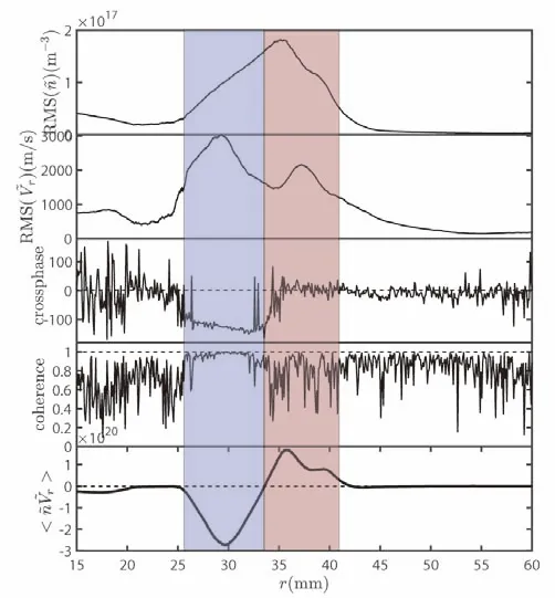
Figure 5.Radial profiles of (a) root mean squares of density fluctuations ,(b) root mean squares of velocity fluctuations ,(c)crossphase between and ,(d) coherence between and at f=1.35 kHz(the frequency of the dominant mode driving inward particle flux) and (e) total particle flux.The blue shaded area shows the area where the inward particle flow occurs,and the red shaded area shows the area where the outward particle flow occurs.
Comparing figures 2(d) and 3,it can be seen thatErshear is negatively correlated with velocity fluctuations in the region where inward flux occurs,suggesting thatErshear effectively suppresses amplitudes of velocity fluctuations.This may be one of the factors that bias voltages can induce the appearance of inward flux by changing theErshear in the core.
4.The low frequency modes driving inward particle flux
For convenience,the following section takes the case where the inward particle flux is the largest as an example.The bias voltage is 90 V and the bias current is 0.8 A.
By filtering the particle flux,as shown in figure 4(c),it can be found that the particle fluxes are mainly driven by the modes between 1 and 2 kHz in general,while the inward particle flux is mainly dominated by the modes of 1.2-1.4 kHz.
By performing Fourier decomposition,the particle flux is written as:
In order to distinguish the dominant factor influencing the direction of particle flux,the trends of the root mean squares of amplitudes,cross phase,and cross coherence from the positive peak to the negative peak are examined in figure 5.From figure 5,we can find that there is a high correlation betweenandand the crossphase cosis about-120°where the inward particle flux occurs.The change in the direction of the particle flux,from outward to inward,is predominantly governed by the crossphase evolution betweenand.In this context,is more significant thanin determining the amplitude of the inward particle flux.
In order to show the mode structure,the two-point crosscorrelation technique [23] has been used atr=26.5 mm andr=29.5 mm.Figure 6 shows thek-spectra at different positions of the inward particle flux area.The spectrum has a typical radial wave number of 1.4 kHz modes (k~ 3 cm-1) at the bias voltage of 90 V and the bias current of 0.8 A.As shown in figure 7,the frequency of the dominant mode driving inward particle flux increases with the biased current.However,the radial wave number (k~ 3 cm-1) of the mode remains unchanged.The frequency of the perturbation mode driving inward particle flux increases from below 1 kHz to 1.2-1.4 kHz.Considering that the turbulent transport in the low frequency is more easily suppressed byErshear.This may partially explain why the inward particle flux increases with the bias current.
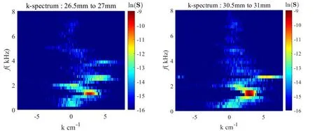
Figure 6.The k-spectrum of potential perturbation between r=26.5 mm and 27 mm,and between r=29.5 mm and 30 mm.Here,k and f denote radial wave number and the frequency,respectively.
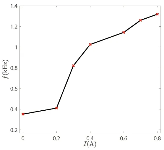
Figure 7.The frequency f of the dominant mode driving inward particle flux with different currents of outermost biased electrodes.
5.Conclusion
In this paper,we report the experiment results of active control of the inward particle flux in the linear plasma device PPT.The formation of inward particle is investigated preliminarily.
Inward particle flux is observed in the PPT device.Additionally,it is found that the particle flux increases with the bias voltages.The bias voltages applied on the outer side change the inward particle flux in the core.It is also found that the profile of radial electric field (Er) shear is flattened by the increased bias voltage.The amplitudes ofVrfluctuation are effectively suppressed byErshear.Therefore,the increased bias voltages drive an increased inward particle flow.Moreover,it is observed that theVrfluctuation has a greater effect thannefluctuation on the inward flux.
There is a high correlation betweennandand the crossphase cosis about -120° where the inward particle flux occurs.In frequency domain,the inward flux is driven by the modes below 1.4 kHz.The frequencyfof the mode driving inward particle flux increases with the current.The typical wave number (k~ 3 cm-1) of these modes remains constant.
The mechanism of the inward particle flux generation needs further studies.It is possible to achieve larger and more controllable inward particle flux if the sparks between two biased electrodes are avoided,and a more stable discharge is possibly available by changing the electrode material as well as the electrode relative position.Besides,the effect of different boundary conditions of the insulation or conductor on the potential distribution can be investigated.
Acknowledgments
This work was supported by the National MCF Energy R&D Program of China (No.2018YFE0303100) and National Natural Science Foundation of China (No.11975038).
杂志排行
Plasma Science and Technology的其它文章
- An improved TDE technique for derivation of 2D turbulence structures based on GPI data in toroidal plasma
- Progress of Lyman-alpha-based beam emission spectroscopy (LyBES) diagnostic on the HL-2A tokamak
- Forward modelling of the Cotton-Mouton effect polarimetry on EAST tokamak
- Development of a toroidal soft x-ray imaging system and application for investigating three-dimensional plasma on J-TEXT
- Electron density measurement by the three boundary channels of HCOOH laser interferometer on the HL-3 tokamak
- Reconstruction of poloidal magnetic field profiles in field-reversed configurations with machine learning in laser-driven ion-beam trace probe