Electron density measurement by the three boundary channels of HCOOH laser interferometer on the HL-3 tokamak
2024-04-06JunrenMOU牟俊任YonggaoLI李永高YuanLI李远ZaihongWANG王再宏BaogangDING丁宝钢HaoxiWANG王浩西JiangYI易江andZhongbingSHI石中兵
Junren MOU (牟俊任) ,Yonggao LI (李永高) ,Yuan LI (李远) ,Zaihong WANG (王再宏) ,Baogang DING (丁宝钢) ,Haoxi WANG (王浩西) ,Jiang YI (易江) and Zhongbing SHI (石中兵)
1 Southwestern Institute of Physics,Chengdu 610041,People’s Republic of China
2 East China Normal University,Shanghai 200241,People’s Republic of China
Abstract Far-infrared (FIR) interferometer is widely used to measure the electron density in the magnetically confined fusion plasma devices.A new FIR laser interferometer with a total of 13 channels (8 horizontal channels and 5 oblique channels) is under development on the HL-3 tokamak by using the formic-acid laser (HCOOH,f=694 GHz).In order to investigate the boundary electron density activity during the divertor discharge,three horizontal interferometry channels located at Z=-97,-76,76.5 cm have been successfully developed on HL-3 in 2023,and put into operation in recent experimental campaign,with a time resolution of < 1.0 μs and lineintegrated electron density resolution of~ 7.0 × 10¹⁶ m-2.This paper mainly focuses on the optical design of the three-channel interferometry system,as well as optical elements and recent experimental result on HL-3.
Keywords: electron density,interferometer,HL-3
1.Introduction
Electron density is one of the most important parameters in the magnetically confined fusion plasmas.Measurement of the refractive index (N) of plasma by using the electromagnetic wave is a well-established tool for measuring the electron density for many decades [1-6].Far-infrared (FIR) laser interferometer detects the line-integrated electron density through launching a beam of FIR laser into the plasma.Because the refractive index of plasma is different from that in the vacuum condition (N=1),some phase difference(corresponding to optical path difference) will generate between the probing beam and the reference beam without passing through the plasma.Based on the interferometry technique,we can achieve the line-integrated electron density by: φ(rad)=k·here,λis the wavelength of electromagnetic wave,neis the local electron density,dlis the line element of integral operation,the coefficientk=(e2/4πc2ε0me)=2.82×10-15,whereeis the elementary charge,cis the light speed,ε0is the dielectric constant of vacuum,meis the mass of electron.
HL-3 is a newly constructed tokamak with major radius of 1.78 m and minor radius of 0.65 m [7,8].HL-3 will focus on high parameter plasma operation and physics research,such as high confinement mode (H-mode),energetic particles driven instabilities,advanced divertor physics,and so on.Aiming to measure the electron density and perform realtime electron density feedback control,a multi-channel formic-acid laser (HCOOH,λ=432.5μm) Michelson-type interferometer was proposed on HL-3,including eight horizontal channels and five oblique channels.Five horizontal channels distributed in the central region (corresponding to the geometry locationZ=-20,-10,0,10,20 cm) had been successfully developed in the early 2023.Subsequently,in order to investigate the boundary electron density activity during the divertor discharge with elongation,other three horizontal interferometry channels located atZ=-97,-76,76.5 cm were recently developed on HL-3.
This paper focuses on the development of the boundary three-channel FIR laser interferometer on HL-3.Section 2 describes the optical design and layout.Section 3 introduces the main components of the interferometry system.Section 4 represents the recent experimental result on HL-3.
2.Optical design and layout
The boundary interferometry system shares the same laser source,front light path,support tower and inner space with the existing five-channel HCOOH laser interferometer,and achieves the electron density measurement through beam splitter.Optical design of the three boundary interferometry channels is based on the Gaussian beam propagation and lens transformation techniques [9-12].
In principle,as a Gaussian beam with wavelength ofλpropagates through the space,its light spot will expand and the diameter (d) can be determined by:
here,Lindicates the distance from the beam waist (d0).
Due to long distance propagation in the interferometry system,it is necessary to employ concave mirror with proper focal length (f) for beam transformation,as shown in figure 1.The beam waist parameter (d2,L2) after beam transformation can be determined from original beam waist (d1,L1) as follows:
Figure 2 shows the optical layout of the HCOOH laser interferometer on HL-3.For the convenience of description,the light paths of central five horizontal channels are also provided in figure 2 by the light color.As the probing wave and local oscillation (LO) wave come out of the long waveguide pipes (~ 19 m),they get into the main optical path.In order to isolate possible vibration from the ground and HL-3 device,all the optical components are assembled on the big optic board which is firmly installed on the large stainlesssteel support tower (7.0 m in height,~ 8 tons in weight) next to the No.5# diagnostic window of HL-3 tokamak.

Figure 1.Principle of the lens transformation for Gaussian beam.
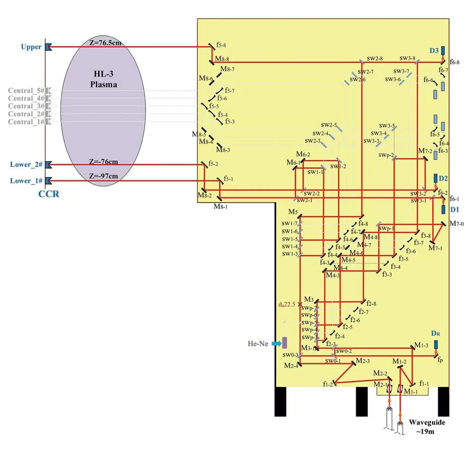
Figure 2.Optical layout of the three boundary interferometry channels (red color),together with the central five horizontal channels (light color).
At the bottom of support tower,two plane mirrors (M1-1,M2-1) are accurately assembled to reflect the probing wave and LO wave into the main optical layout.In order to derive the reference beat signal (R),firstly,small parts of probing beam and LO beam are individually separated out by the mesh-grid splitters,and then combined at the second meshgrid.Finally,the combined waves are received by the high responsivity Schottky diode detector (DR),generating the beat signal (R).
For the probing beam of the three boundary interferometry channels,the design of light path is based on existing central five interferometry channels through adding meshgrid splitters with proper transmission/reflection ratio.For the two lower boundary channels,their probing waves are obtained through separating some light-intensity from previous central channel 1# and channel 3#,respectively.For the upper boundary channel,its probing wave is obtained through separating some light-intensity from central channel 5#.Similarly,the LO waves of the three boundary interferometry channels are achieved through separating wave from central channels 1#,3#,5#,respectively.The probing waves are orderly launched into HL-3 plasma alongZ=-97,-76,76.5 cm,and reflected by the metal retro-reflector.Because the boundary interferometry channels are close to the plasma edge,where the electron density is very low,the refraction effect caused by the density gradient is weak.Meanwhile,the size of reflectors is big enough to receive the probing beams from plasma.Finally,the probing wave carrying the information of electron density combined with the outside LO waves,and received by the Schottky diode detectors (D1,D2,D3),generating the probing beat signals (P1,P2,P3).Finally,the line-integrated electron density can be achieved by computing the phase difference between P and R.
3.Main components of the diagnostic
3.1.Terahertz formic-acid laser source
The FIR laser interferometer on the HL-3 tokamak shares the terahertz formic acid (HCOOH) laser source with HL-2A tokamak [13,14].In practical operation,two FIR laser diagnostics can be freely switched by a removable plane mirror which is mounted close to the lasers.HCOOH laser is optically pumped by a high-power CO2laser (~ 50 W).A Fabry-Perot (FP) cavity is employed to stabilize the CO2pump laser’s frequency for optimal FIR pumping.The process involves sending the laser through the FP,detecting the transmitted signal with a phase-sensitive detector (PSD),and then the length of the FP is dithered about the nominal point.The PSD output reflects the frequency difference between the FP and CO2pump laser.
The HCOOH laser emits linearly polarized Gaussian radiation with a wavelength of 432.5μm,beam waist of 11.0 mm and output power level of 15-25 mW in operation.Two HCOOH lasers are utilized here for heterodyne detection,and beat intermediate frequency (IF) in several megahertz can be obtained by slightly tuning the cavity length of HCOOH laser,so that the time resolution of (< 1.0μs) can be achieved for the interferometry system.
3.2.Diagnostic window
The newly developed three boundary interferometry channels are mainly used to analyze the electron density activity close to plasma boundary region during the divertor discharge with large elongation.Limited by the spatial structure of HL-3 tokamak around No.5# section,only three probing channels are considered,in which one channel is located at the upper windows (ϕ300 mm) and two channel are located at the lower window (ϕ300 mm),respectively.
Figure 3 shows the lower diagnostic window as an example.To ensure the minimum loss of light intensity at the diagnostic window,the aperture size (ϕ65 mm) is chosen to satisfy the design requirement.Aiming to withstand the high temperature baking on HL-3 (up to 300 °C),the FIR diagnostic windows in the boundary region are specially designed with an extended neck of 150 mm long.As a result,the temperature can fast drop at the position of crystal quartz plate and fluor rubber ring can be used for vacuum seal.In addition,to avoid the disturbance of reflected wave from the crystal quartz plate,three diagnostic windows are specially designed with 3.0° slant angle.Figure 3 gives the designed structure and picture of two lower diagnostic windows (ϕ65 mm).

Figure 3.Design and picture of the lower diagnostic window (ϕ300 mm) for the HCOOH laser interferometer on HL-3.
3.3.In-vacuum retro-reflector
In the Michelson-type interferometry configuration,the probing wave doubly passes through HL-3 plasma,so that the in-vacuum retro-reflector is required for beam reflection.On HL-3,three corner-cube-reflectors (CCR) which are made of copper with gold-plating are used for the boundary interferometry channels.CCR consists of three mutually perpendicular plane mirrors [15,16].Due to optic characteristic of the CCR,the reflected wave can propagate along the same path of incident wave by controlling the beam waist at the central area of CCR.These CCRs have an effective aperture of 50 mm,and all dihedral angle tolerances are less than 20".Figure 4shows the picture of CCR on HL-3 and primary test by using the visible laser (λ=635nm).In the desktop test,visible laser orderly passes through the splitter and diaphragm,and then launches to the center of CCR which is~ 3.0 m away from the diaphragm.The experimental result indicates that the reflected laser beam centrally crosses the diaphragm and can be observed below the splitter,which proves that the incident laser is perfectly reflected by the CCR along the same path.
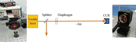
Figure 4.Desktop test of the CCR by using the visible laser.
3.4.Data processing system
The data processing system completes the phase difference computation and fast data acquisition.Figure 5 briefly displays the workflow of the data processing system,which starts to work as soon as receiving the trigger signal from HL-3 master control system.Firstly,the probing beat signal(P) and reference beat signal (R) output from detectors pass through band-pass filter and then are treated by 16-bit analogto-digital converter (ADC) with sampling frequency of 10 MHz.Here,Field Programmable Gate Array (FPGA) is the key module used to compute the phase difference between P and R,based on the digital phase comparator technique [17-19].The raw beat signals and phase data are temporarily saved in the DDR-III and then uploaded to HL-3 database through fast PXIe bus for offline data analysis.Besides,the computed phase data is transmitted to a digitalto-analog converter (DAC) and delivered to HL-3 master control system for real-time density feedback control with a time delay < 1.0 ms.
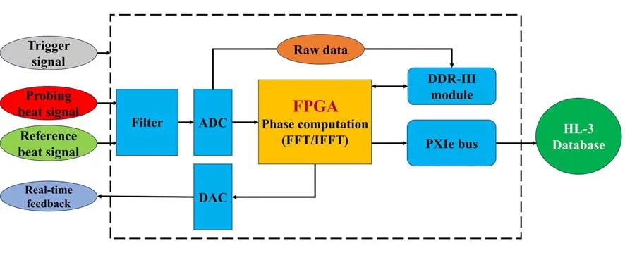
Figure 5.Workflow of data processing system of the FIR laser interferometer.
4.Experimental result on the HL-3 tokamak
In the 2023 experimental campaign on the HL-3 tokamak,the newly developed three boundary interferometry channels were firstly put into operation and successfully measured effective electron density data.During the divertor discharge,the boundary interferometry channels are effective for investigating the electron density activity near the edge of plasma.
Figures 6(a)-(c) give an example of experimental measurement on HL-3.In this shot No.2164#,the plasma current is~ 300 kA and the line-integrated electron density is~ 1.5 × 10¹⁹m-2during the plasma flat-top phase.From the line-integrated electron densities shown in the figures 6(a)-(d),we can see that both boundary and central interferometry channels are sensitive to the supplementary gas puffing.In comparison,the evolution processes of electron density in figures 6(a)-(c) show more details due to the change of plasma configuration.The value of line-integrated electron density is generally smaller than 0.3 × 10¹⁹m-2,which is about one order smaller than that in the plasma central region.For the upper channel shown in figure 6(a),the electron density shows bigger and faster change before 500 ms and then decreases.In the following phase,it gradually increases induced by gas puffing.On the contrary,the electron density measured by the lower two channels shows smaller before 400 ms and then increases in figures 6(b) and(c).In particular,figure 6(c) clearly reflects the density modulation process,and keeps steady level during the time of 400-1500 ms.For the three boundary channels,the channel (Z=-76 cm) shows higher electron density than other two channels (Z=-97,76.5 cm),due to themselves detected positions and plasma vertical displacement which is shown in figure 6(e) during the divertor discharge.Figure 6(f)represents the plasma current (Ip),Dαemission (DVS-Dα) of the divertor region,and the gas puffing whose position is at the mid-plane.
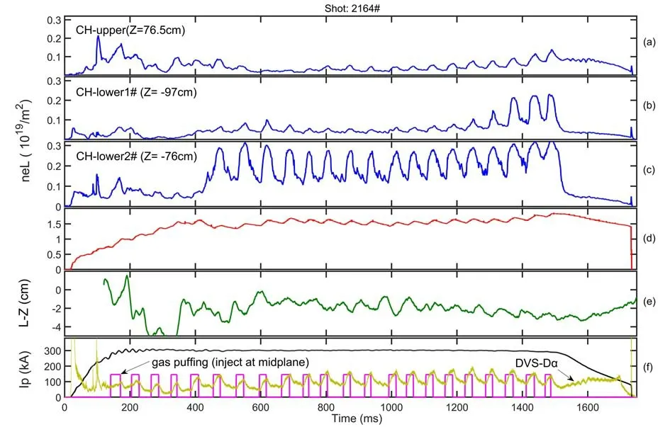
Figure 6.(a)-(c) Temporal evolution of the line-integrated electron density measured by the boundary interferometry channels (Z=76.5,-97,-76 cm),(d) line-integrated electron density measured by the central channel (Z=0 cm),(e) plasma vertical displacement,(f) plasma current,gas puffing signal and Dα emission in the divertor region.
5.Summary
Measurement of the electron density is very crucial for the plasma discharge operation and understanding of plasma physics.In order to investigate the boundary electron density activity during the divertor discharge on HL-3,three boundary interferometry channels located atZ=-97,-76,76.5 cm have been firstly developed in 2023,based on the existing central five-channel HCOOH laser interferometer.
In recent HL-3 experimental campaign,the line-integrated electron density of three channels is able to steadily operate with a time resolution of < 1.0μs,line-integrated electron density resolution of~ 7.0×10¹⁶m-2.From the experimental result,we can observe that the line-integrated electron density in the plasma boundary region is one order smaller than that in the central region.Meanwhile,detailed variation activity of electron density can be investigated by the boundary channel.The newly developed boundary interferometry system will be helpful for the research of plasma physics of divertor discharge.
In the near future,some other oblique channels will be developed to improve the constraint of the electron density profile reconstruction,and the interferometry system also will be upgraded into the three-wave based polarimeter/interferometer which can simultaneously detect the electron density and Faraday rotation angle.
Acknowledgments
The corresponding author (Yonggao Li) would like to express sincere thanks to Dr.Yan Zhou,Zhongchao Deng,and Bihe Deng for their helpful suggestion on the diagnostic development,to the engineers Jin Wang,Wei Zhang,Ruijun Li,Linze Wu,Guohui Fu and Hong Xu for their help in the assembly work of the interferometry system.This work was supported by the National Magnetic Confinement Fusion Science Program of China (Nos. 2019YFE03020004,2018YFE0304102 and 2019YFE03020002) and the Department of Science and Technology of Sichuan Province (No.2020YJ0463).
猜你喜欢
杂志排行

Plasma Science and Technology的其它文章
- An improved TDE technique for derivation of 2D turbulence structures based on GPI data in toroidal plasma
- Inward particle transport driven by biased endplate in a cylindrical magnetized plasma
- Progress of Lyman-alpha-based beam emission spectroscopy (LyBES) diagnostic on the HL-2A tokamak
- Forward modelling of the Cotton-Mouton effect polarimetry on EAST tokamak
- Development of a toroidal soft x-ray imaging system and application for investigating three-dimensional plasma on J-TEXT
- Reconstruction of poloidal magnetic field profiles in field-reversed configurations with machine learning in laser-driven ion-beam trace probe