The research progress of an E//B neutral particle analyzer
2024-04-06LongMA马龙YufanQU屈玉凡YuanLUO罗圆DehaoXIE谢德豪YanxiWANG汪彦熹ShuoWANG王硕GuofengQU曲国峰PeipeiREN任培培XiaobingLUO罗小兵XingquanLIU刘星泉JifengHAN韩纪锋RoyWADAWeipingLIN林炜平LingeZANG臧临阁andJingjunZHU朱敬军
Long MA (马龙) ,Yufan QU (屈玉凡) ,Yuan LUO (罗圆) ,Dehao XIE (谢德豪) ,Yanxi WANG (汪彦熹) ,Shuo WANG (王硕) ,Guofeng QU (曲国峰),Peipei REN (任培培),Xiaobing LUO (罗小兵),Xingquan LIU (刘星泉),Jifeng HAN (韩纪锋),Roy WADA,Weiping LIN (林炜平),*,Linge ZANG (臧临阁),*and Jingjun ZHU (朱敬军),*
1 Key Laboratory of Radiation Physics and Technology of the Ministry of Education,Institute of Nuclear Science and Technology,Sichuan University,Chengdu 610064,People’s Republic of China
2 Southwestern Institute of Physics,Chengdu 610064,People’s Republic of China
3 Cyclotron Institute,Texas A&M University,College Station,Texas 77843,United States of America
Abstract An E// B neutral particle analyzer (NPA) has been designed and is under development at Sichuan University and Southwestern Institute of Physics.The main purpose of the E// B NPA is to measure the distribution function of fast ions in the HL-2A/3 tokamak.The E// B NPA contains three main units,i.e.the stripping unit,the analyzing unit and the detection unit.A gas stripping chamber was adopted as the stripping unit.The results of the simulations and beam tests for the stripping chamber are presented.Parallel electric and magnetic fields provided by a NdFeB permanent magnet and two parallel electric plates were designed and constructed for the analyzing unit.The calibration of the magnetic and electric fields was performed using a 50 kV electron cyclotron resonance ion source (ECRIS) platform.The detection unit consists of 32 lutetium-yttrium oxyorthosilicate (LYSO) detector modules arranged in two rows.The response functions of α,hydrogen ions (H+,) and γ for a detector module were measured with 241 Am,137 Cs and 152Eu sources together with the 50 kV ECRIS platform.The overall results indicate that the designed E// B NPA device is capable of measuring the intensity of neutral hydrogen and deuteron atoms with energy higher than 20 keV.
Keywords: E//B neutral particle analyzer,gas stripping,lutetium-yttrium oxyorthosilicate,electron cyclotron resonance ion source platform
1.Introduction
The neutral particle analyzer (NPA) [1-9] is one of the critical diagnostic devices in tokamak facilities [10-15].It can provide the energy distribution function of fast ions,which is of great importance in the frontier physics study of energetic particles [16-22],and the isotope composition by measuring the charge exchange neutral particles (H,D,T and α) escaping from the hot plasma.Since the first historic NPA was built [1] and applied [23] on an Alpha magnetic confinement system,a large number of different types of NPAs have been successfully developed around the world [1-9].For example,theE//Bspectrometer [6] developed at the Princeton Plasma Physics Laboratory has an energy range of 0.5 <A(amu)E(keV) < 600 and a mass resolution of H+,D+and T+(or3He+) ions.The compact NPA [5] developed for the Wendelstein 7-AS stellarator facility had the main advantage of providing simultaneous analysis for hydrogen (0.8-80 keV) and deuterium (0.8-40 keV) with a more compact structure (size: 169 mm × 302 mm × 326 mm,weight:42.5 kg).
A newE//BNPA is under development at Sichuan University and Southwestern Institute of Physics for the measurement of the fast ion distribution function in the HL-2A/3 tokamak.It is designed to measure H and D atoms in the energy range of 20-200 keV,with energy resolutions of 30% at 20 keV and 10% at 200 keV.It consists of a stripping unit,an analyzing unit and a detection unit.A gas stripping chamber was adopted to ionize the neutral particles [24,25].An analyzing unit with tandem-type parallel electric and magnetic fields was designed to realize the designed mass and energy resolutions [25,26].A detector array consisting of 32 lutetium-yttrium oxyorthosilicate (LYSO) detector modules arranged in two rows was developed to measure the ions with different energies and masses.
In this article,we present the recent progress in the development of the aboveE//BNPA.The article is organized as follows.The results of the simulations and beam tests for the stripping unit are presented in section 2.The design and calibration of the analyzing unit are given in section 3.The responses and the low energy limit of the LYSO detector module are presented in section 4.A brief summary is given in section 5.
2.Stripping unit
The stripping unit provides a place to ionize the neutral particles escaping from hot plasma.To avoid replacing the damaged stripping foil frequently and for easy maintenance,a gas stripping chamber was adopted as the stripping unit for theE//BNPA. H2gas was chosen as the stripping gas to avoid introducing additional elements into the tokamak,which would damage the plasma operation.A cylinder chamber with two identical differential pipes was employed as the stripping chamber.The main purpose of adopting this structure was to maintain a high pressure in the stripping chamber and a high vacuum in the outside vacuum chamber.Figure 1 shows a schematic view of the updated stripping unit,which is a further optimized version of the design in reference [24,25],where the inner diameter of differential pipes is reduced from 4 mm to 2 mm,and the length of the gas chamber is increased from 56 mm to 82 mm.
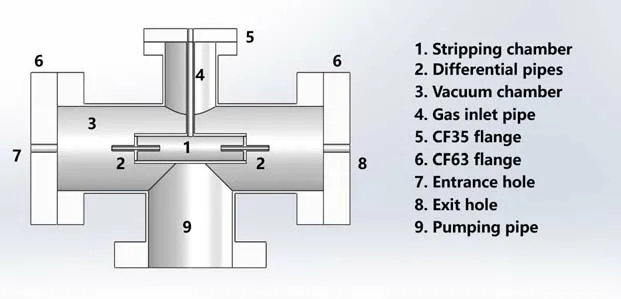
Figure 1.Schematic view of the updated gas stripping unit.
An updated stripping unit with a Faraday cup (FC) in the downstream vacuum chamber was constructed.Figure 2 shows a photo of the unit.A needle valve together with an electromagnetic valve controlled by a proportional-integralderivative controller was connected to the gas inlet flange to maintain the stability of the H2gas flow.Two diaphragm vacuum gauges,Pfeiffer CMR362 and CMR365,were used to measure the pressure at the gas inlet (P0) and the vacuum chamber,respectively.Applying the two measured pressures as the boundary conditions in the computational fluid dynamics (CFD) calculation using Ansys Fluent [24,27],the pressure distribution along the path of the incident neutral particles was obtained.Figure 3 shows a typical pressure distribution along the path of the incident neutral particles in the stripping chamber for the gas inlet pressure ofP0=40 Pa.A constant pressure of around 31 Pa,which is more than three times that in a previous design [24],in the center of the stripping chamber,and a linear decreasing pressure inside the differential pipe were obtained from the Ansys Fluent calculations.
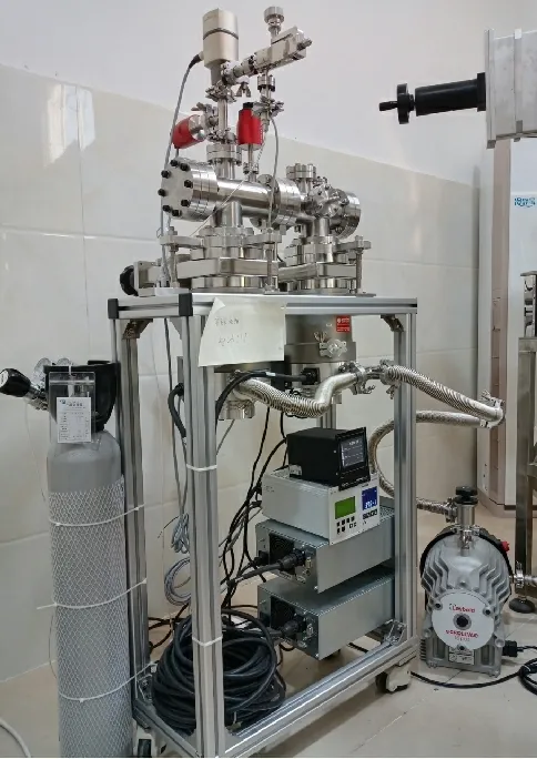
Figure 2.Photo of the updated stripping unit.

Figure 3.Typical pressure distribution of P0=40 Pa in the path of the incident neutral particles in the stripping chamber.
In our previous work in reference [24,25],a GEANT4[28,29] Monte Carlo simulation code was applied to simulate the global stripping efficiency (R×f+1) of an earlier version of the stripping unit.By changing the structure and the pressure distribution in the code to match the updated stripping unit,updated global stripping efficiencies were obtained for the incident H and D atoms in the energy range of 20-200 keV.Figure 4 showsR×f+1as a function of the gas inlet pressureP0for H and D atoms with incident energies of 20,100 and 200 keV in (a),(b) and (c),respectively.As the thickness of the stripping gas increases in the updated stripping chamber,a lowerP0value is obtained to get the same global stripping efficiency,compared to theP0value in the previous unit.The global efficiency increases as the gas inlet pressureP0increases and reaches a maximum value atP0of around 40 Pa for the maximum designed energy (200 keV) in the updated stripping chamber.The pressureP0=40 Pa,which is four times less than that in the previous design [24],is obtained as the optimum working pressure for the stripping unit.
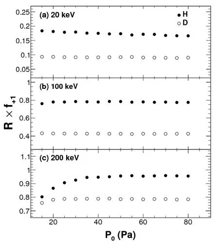
Figure 4.Global effeciency R×f+1 as a function of the gas inlet pressure P0 for incident energies of 20 keV (a),100 keV (b),200 keV(c).The solid and open circles represent H and D,respectively.
Since neutral particles are not easy to handle as the incident particles for a precise measurement,it is difficult to make direct verification of the simulated results in the laboratory.However,since the stripping cross-sections from neutrals to ions and the captured cross-sections from ions to neutrals are comparable at a given energy [24],the verification can be performed in a reverse scenario,using the ion beams.In the following part we describe the results in this scenario.The reverse experiments were performed using the 50 kV electron cyclotron resonance ion source (ECRIS) platform at Sichuan University.Figure 5 shows a schematic diagram of the ECRIS platform.A 30° bending dipole magnet was connected to the ECRIS to select different beam species.A collimator with a diameter of 5 mm was installed between the ECRIS and the dipole magnet to limit the beam spot.In the experiment,the stripping unit was connected to the ECRIS platform downstream of chamber B.Proton beams with incident energies of 5,10,20,30 and 40 keV were delivered to the entrance hole of the stripping unit.After undergoing the charge exchange processes in the stripping chamber filled with H2gas,the sum current of the charged particles was measured by the FC in the downstream chamber of the stripping unit.Before and after each measurement,the beam current without the H2gas was also measured as a reference.Figure 6 shows the ratio of current with and without H2gas as a function of the proton energy for gas inlet pressures ofP0=20,30 and 40 Pa.The current ratio increases rapidly as the proton energy increases for allP0values.Above the incident energy of 10 keV,a decreasing trend of less than 30% is found whenP0increases for a given incident energy.At the lowest incident energy of 5 keV,on the other hand,the current ratio decreases by more than 50% whenP0increases from 20 Pa to 40 Pa.A further detailed comparison of the measurement and that of the GEANT4 simulation is underway.
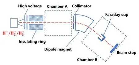
Figure 5.Schematic diagram of the 50 kV ECRIS platform.
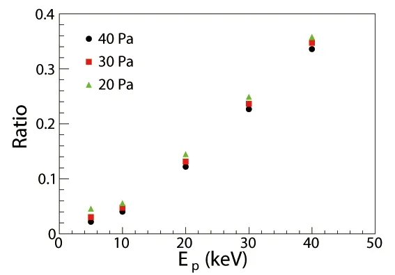
Figure 6.FC current ratio of the measurement with and without H2 gas as a function of the proton energy.Circles,squares and triangles represent P0=40,30 and 20 Pa,respectively.
3.Analyzing unit
In the analyzing unit,parallel electric and magnetic fields were adopted to realize the designed mass and energy resolution.COMSOL multiphysics simulation software [30] was used to design the electric and magnetic fields.The design of the analyzing unit was presented in our previous work in reference [25,26].The magnet is composed of a yoke and two poles,with two pieces of NdFeB magnet placed between them.The residual magnetic field strength of the NdFeB magnet isBr=1.2 T.A maximum magnetic field strength of 0.8 T was obtained at the gap.Two polished copper plates with a space of 2 cm were used as the electric plates,and the electric field was set to 5 kV cm-3.Figure 7 shows the simulation results of the ion trajectories using COMSOL software.The H+and D+ions in the energy range of 20-200 keV (10-200 keV for D+) are clearly separated.
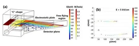
Figure 7.COMSOL simulation of the analyzing unit.
The permanent magnet and the electric plates were constructed according to the design.The ion beam calibration of the magnetic and electric fields was performed at the 50 kV ECRIS platform at Sichuan University.A trapezoidshape vacuum chamber was constructed to embed the permanent magnet and the electric plates.A collimator with a hole diameter of 3 mm was placed at the entrance flange of the vacuum chamber to limit the beam spot size.In order to record the ion position at the detector plane,a transparent glass plate with a thin Ag/ZnS foil on the entrance surface was placed at the detector plane.The ion position was then recorded by a camera taking photos through the glass window of the vacuum chamber.Figure 8 shows a photo of the vacuum chamber installed on the ECRIS platform in (a)and a photo of the magnet-electrode arrangement inside the vacuum chamber in (b).
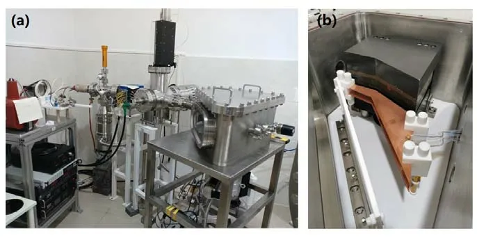
Figure 8.Photos of the vacuum chamber installed on the ECRIS platform (a) and the magnet-electrode arrangement inside the vacuum chamber (b).
Three beam species,i.e.,were producedby the ECRIS when working with H2gas.Sinceand D+have the same charge and a similar mass,they have almost the same trajectory in the magnetic and electric fields,and hit the same position at the detector plane.Therefore,thecluster beam was used to test the magnetic and electric fields instead of D+.Figure 9 shows a photo of the 35 keV proton beam position on the detector plane recorded by the camera.The blue rectangle spot is the proton beam position.The spreading of the beam spot in the horizontal direction is about 5 mm,which is caused by different entrance positions in the horizontal direction at the entrance surface of the magnet.The spot size in the vertical direction is about 2 mm,which is smaller than the diameter of the collimator.This indicates that a focusing trajectory of the ions in the vertical direction was achieved for the designed magnetic field.The experimental data of the ion beam test are under further analysis.
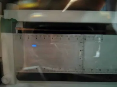
Figure 9.Position of the 35 keV proton beam on the detector plane recorded by the camera.The blue rectangle spot is the proton beam position.
4.Detection unit
Several kinds of detectors have been applied to detect the ionized particles in NPA,such as an ion-electron transformer together with a scintillator counter [1,4],a scintillator deposited on a photomultiplier tube [2,3],a channel electron multiplier [5] and a microchannel plate detector [6].Considering the high neutron background and large stray magnetic fields near the tokamak facility,an inorganic scintillator of LYSO coupled to the Silicon PhotoMultiplier(SiPM) was adopted as the detector module.It has the advantages of fast time response,low operation voltage,insensitivity to the magnetic fields,suitability for bareness use and easy machining.The detection unit was designed to have 32 detector modules arranged into two rows.A prototype detector module was constructed using a bare LYSO crystal with a sensitive surface of 6 mm × 6 mm and a thickness of 1 mm coupled to a Hamamatsu SiPM [31] with the same sensitive area.According to the COMSOL simulation,the 6 mm × 6 mm sensitive area can achieve the designed energy resolution.The main function of the detector module is to count the low-energy ions with a high efficiency.The efficiency at the low-energy limit of the module is crucial for the NPA application.On the other hand,the energy measurement is not crucial for this application,since the detector is used as a hit detector.However,the LYSO crystal has a natural background from176Lu β decay.Thus,the energy measurement may be useful to evaluate the background contribution in the actual measured counts.
A241Am source was used to measure the response of the detector module.The signal was recorded using a CAEN DT5724B digitizer.By changing the distance between the source and the LYSO surface of the module in the air,the response function for the α particles was obtained.Theα energy deposit inside the LYSO crystal was obtained using SRIM [32].Figure 10 shows the spectra of the241Am source measurements.The background mainly comes from the β decay of176Lu in the LYSO crystal.The counting rate of the background is~ 10 Hz,which can be further reduced by reducing the thickness of the LYSO.The peaks around the 40 channel and 200 channel are the two low-energy γ rays of 13.9 and 59.5 keV from the241Am source.One can see in figure 10 that the α peak position decreases as the distance increases.The137Cs and152Eu sources were also used together with the241Am source to obtain the response of lowenergy γ rays in the module in separate runs.γ rays of 32.19 keV and 661.66 keV from137Cs,and of 40.12 keV,89.85 keV and 121.78 keV from152Eu,were also measured to evaluate the response of the γ rays.
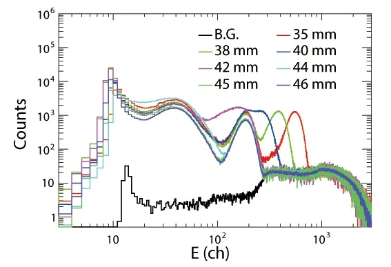
Figure 10.Energy spectra of the 241Am source test.The black,red,green,blue,pink,cyan,dark green and dark blue histograms represent the background measurement,and measurements at distances of 35,38,40,42,44,45 and 46 mm.
In the α response measurements,low-energy α particles were obtained by passing through a certain thickness of air.The straggling in the air causes large uncertainty in the α energy,especially at the low-energy end.More accurate measurements were performed at the 50 kV ECRIS platform.Figure 11 shows the detector setup in the ECRIS platform.A collimator with a very small hole of 0.05 mm diameter was installed upstream of the 5 mm collimator shown in figure 5 to reduce the beam intensity.Another 3 mm collimator was installed 40 mm in front of the LYSO to restrict the beam spot.Thebeams were delivered to the detector module through the collimators.The counting rate was limited below 2000 Hz during the experiments.Figure 12 shows the spectra of H+beams with energies of 2.5,5,10,20 and 40 keV in the black,red,green,blue and pink histograms,respectively.The solid curves are the Gaussian fit around the peaks.A threshold around the 10 channel cuts off more than half the peak for 2.5 and 5 keV H+,and about 10% for 10 keV,which is acceptable and can be corrected for the NPA application.give similar results.These results indicate that a low-energy limit of 10 keV is achieved for the detector module in hydrogen ion measurement.
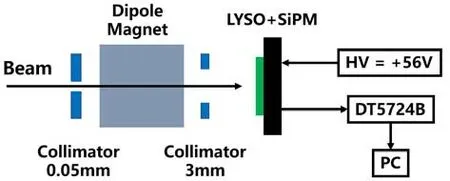
Figure 11.Setup of the detector module in the ECRIS platform.
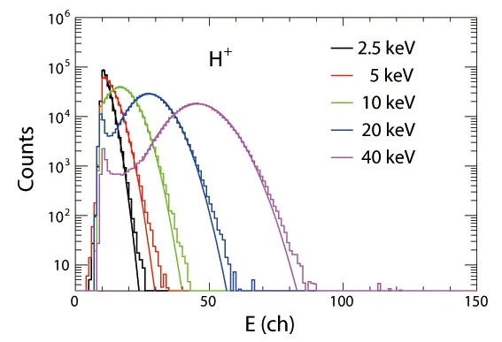
Figure 12.Spectra of H+ beams with energies of 2.5 (black),5 (red),10 (green),20 (blue) and 40 keV (pink).The solid curves are the Gaussian fit around the peak.
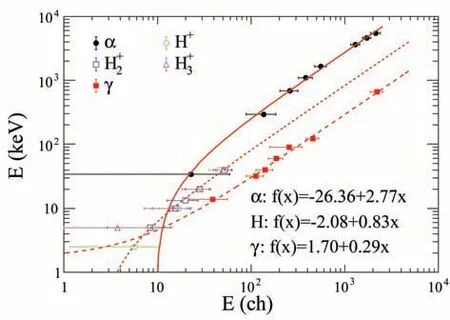
Figure 13.Responses of α,H+, and γ in the detector module.Solid,dashed and long dashed curves are the linear fit of α,hydrogen ions and γ,respectively.
The responses of α,H+,and γ are summarized in figure 13.The error bars of the data points are the full width at half maximum of the Gaussian fits.The solid,dashed and long dashed curves are the linear fit of α,hydrogen ions (H+,and) and γ,respectively.One can see in figure 13 that three clearly separate curves indicate different response functions for α,hydrogen ions and γ in the module.A larger pulse height is obtained for the lighter charged particles (γ is equivalent to its secondary electrons).Due to the large errors for the low-energy α particles andγ rays,and the lack of lower energy measurement,the extrapolated zero points show some deviations among the different particles.The linear changes in the energy as a function of the channel number for α,hydrogen ions and γ indicate good responses for these particles in the module.
The energy range designed for theE//BNPA is 20-200 keV.As shown in figure 12,about 90% of 10 keV protons were detected by the detector module and nearly 100%of the 20 keV protons were detected.This indicates that the detector module has sufficient efficiency for protons in the designed energy range.Theparticles have similar results,which indicates that the detector module also has nearly 100%efficiency for D+particles.As presented in figure 13,the responses of the γ rays are almost 10 times larger than those of α particles at γ energies higher than 10 keV and a few times larger than those of hydrogen ions at hydrogen energies below 50 keV.These high γ responses could be a potential problem when using the LYSO detector array in a high gamma ray background.Therefore,it is necessary to reduce the γ sensitivity and the background γ rays from the tokamak facility.To reduce the γ sensitivity,the thickness of the LYSO detector is reduced to 0.08 mm for the updated unit from the one with 1 mm used in the test experiments.For the background γ rays,sufficient additional shielding outside the vacuum chamber of theE//BNPA device may be required.
5.Summary
AnE//BNPA was designed and is under development for the HL-2A/3 facility to study the frontier physics of fast ions.A gas stripping chamber with two differential pipes was adopted as the stripping unit.An updated stripping unit with an FC was constructed.The pressure distribution inside the stripping chamber was studied using Ansys Fluent with the measured boundary pressures.A GEANT4 Monte Carlo code was applied to study the stripping efficiency of the stripping unit,and an optimum gas inlet pressure ofP0=40 Pa was obtained.The ion beam tests of the stripping efficiency were carried out at the 50 kV ECRIS platform at Sichuan University.An increasing trend of the measured current ratio was observed as the incident energy increased.Further comparison of the GEANT4 simulations and the experiments is currently in progress.The analyzing unit with the parallel electric and magnetic fields was designed using COMSOL multiphysics software.A permanent magnet with a maximum magnetic field strength of 0.8 T was designed and constructed to provide the magnetic field.Two parallel electric plates made of copper were used to provide the 5 kV cm-1electric field.The calibration of the analyzing unit was also performed at the 50 kV ECRIS platform.The particle position was recorded by the Ag/ZnS foil placed at the detector plane.The detection unit consisted of 32 LYSO detector modules arranged in two rows.The response functions of α,hydrogen ions (H+,) and γ in the detector module were measured with241Am,137Cs and152Eu sources together with the 50 kV ECRIS platform.The overall results indicate that the designedE//BNPA device is capable of measuring the intensity of neutral hydrogen and deuteron atoms with energy higher than 20 keV.
Acknowledgments
This work was supported by the National Magnetic Confinement Fusion Energy R&D Program of China (No.2018YFE0310200),National Natural Science Foundation of China (Nos.11705242,11805138 and 12175156) and the Fundamental Research Funds for the Central Universities in China (Nos.YJ201820 and YJ201954).
猜你喜欢
——例谈尊重与正确归因在建立和谐师生关系中的重要价值
杂志排行

Plasma Science and Technology的其它文章
- Forward modelling of the Cotton-Mouton effect polarimetry on EAST tokamak
- First results of CO2 dispersion interferometer on EAST tokamak
- Reconstruction of poloidal magnetic field profiles in field-reversed configurations with machine learning in laser-driven ion-beam trace probe
- Electron density measurement by the three boundary channels of HCOOH laser interferometer on the HL-3 tokamak
- Development of a toroidal soft x-ray imaging system and application for investigating three-dimensional plasma on J-TEXT
- Inward particle transport driven by biased endplate in a cylindrical magnetized plasma